 Open Access Article
First-principles investigations on the anisotropic elasticity and thermodynamic properties of U3Si2–Al
Xinyu Chenab,
Yanqing Qinb,
Diwei Shic,
Yaolin Guob,
Moran Bub,
Tao Yanb,
Jiexi Songd,
Guoquan Liu*a,
Yiming Zhang *b and
Shiyu Du
 *b
*b
aSchool of Sciences, Hebei University of Science and Technology, Shijiazhuang 050018, China. E-mail: liuguoquan62@126.com
bEngineering Laboratory of Nuclear Energy Materials, Ningbo Institute of Industrial Technology & Engineering, Chinese Academy Sciences, No. 1219 Zhongguan West Road, Zhenhai District, Ningbo, Zhejiang Province 315201, P. R. China. E-mail: dushiyu@nimte.ac.cn; ymzhang@nimte.ac.cn
cSchool of Physical Science and Technology, ShanghaiTech University, Shanghai 201210, China
dDepartment of Applied Physics, Northwestern Polytechnical University, Xi'an 710072, China
First published on 22nd September 2020
Abstract
U3Si2 has been tested as a new type of nuclear fuel, and Al has been proven to improve its oxidation resistance. However, there is no research on its anisotropic mechanical and thermal properties. The mechanical and thermal properties of Al-alloyed U3Si2 nuclear fuel are calculated on the basis of first principles. Through the phonon dispersion curves, two kinetic stable structures sub-U3Si1.5Al0.5 and sub-U2.5Si2Al0.5(I) are screened out. It is found that the toughness of these two compounds after alloying are significantly improved compared to U3Si2. The three-dimensional Young's modulus shows that, the sub-U3Si1.5Al0.5 formed by Al alloying in U3Si2 maintains a higher mechanical isotropy, while sub-U2.5Si2Al0.5(I) shows higher mechanical anisotropy, which is consistent with the value of Au. The calculation result shows that the lattice thermal conductivity of sub-U3Si1.5Al0.5 and sub-U2.5Si2Al0.5(I) after alloying exhibits high isotropy as the temperature increases.
1 Introduction
Uranium dioxide (UO2) is currently the most widely used fuel for commercial light water reactors.1–4 Traditional UO2 fuel has the advantages of high melting point, outstanding radiation performance and exceptional compatibility with cladding materials, but it has the disadvantage of low thermal conductivity.2,5 In the context of the Fukushima nuclear accident, the research on the accident-tolerant fuel system (ATF) has attracted the interests of many researchers.6,7 Replacing UO2 with new nuclear material is one of the focuses for the ATF development and ensures that the new fuel has high thermal conductivity and other advantageous properties.8One type of ideal candidate material for ATFs is uranium-silicon fuel,9,10 and there have been studies on the microstructure changes of uranium-silicon alloys under irradiation conditions.11 The currently known types of uranium silicon compounds are U3Si2, U3Si, USi2, USi and so on. U3Si2 has ultra-high thermal conductivity and high uranium-containing density among uranium silicon compounds, which has attracted many researchers' attentions.10,12,13 Due to poor mechanical performance and antioxidant capacity, alloying the U3Si2 is an effective solution for further application within light water reactors.14 Wood et al.15 studied the effect of adding Al elements into U3Si2 on their performance through thermal reanalysis, and the investigation showed that U3Si2 oxidation behavior could be postponed, which confirmed that U3Si2 antioxidant resistance was improved by adding Al elements.
Experimental and theoretical studies on the U–Si–Al ternary system have been carried out around the world over past years. Marín et al.16 mixed the U3Si2 powder with Al to produce intermetallic compound U(Al,Si)3 at melting temperature of aluminum, indicating that this strategy could be adopted to manufacture U3Si2–Al dispersed fuel. Wang et al.17 observed the occurrence and spread of interlayer cracks within U3Si2–Al dispersed fuel plates by scanning electron microscopy and analyzed the mechanisms of the crack formation; and proved that their mechanical properties, especially fatigue properties, were greatly influenced by the processing method of the fuel plates. Through transmission electron microscope, Gan et al.18 observed the average diameter, number density and volume fraction of the fuel matrix interaction layer (Si–Al)/U of U3Si–Al fuel plate after irradiation, as well as the average diameter, number density and volume fraction of small bubbles within the fuel particles; and discussed their effects on fuel performance. Rabin et al.19 established a thermodynamic model of the U–Si–Al ternary system using computational phase diagram method, and conducted novel experiments in the aluminum-silicon-depleted uranium area; which showed that under equilibrium conditions, the silicon content of U(Al,Si)3 is significantly higher than previously reported ones. Zenou et al.20 used electron crystallography and powder X-ray diffraction techniques to study the structure and bonding of a stable ordered U(Al,Si)3 phase, and results showed that Si was locating closer to U than Al; and when the energy was stable, the U–Si bond energy was stronger than the U–Al bond energy. Mirandou et al.21 studied two U3Si2–Al fuel plates by scanning electron microscopy and transmission electron microscopy, and the results showed that the final structure was composed of U(Al,Si)3 and some modified U3Si2 phase which had the same crystal structure with U3Si2. Suparlina et al.22 examined the properties of U3Si2–Al fuel plate after irradiation, and the results showed that the properties were satisfied within the limits by safety standards.
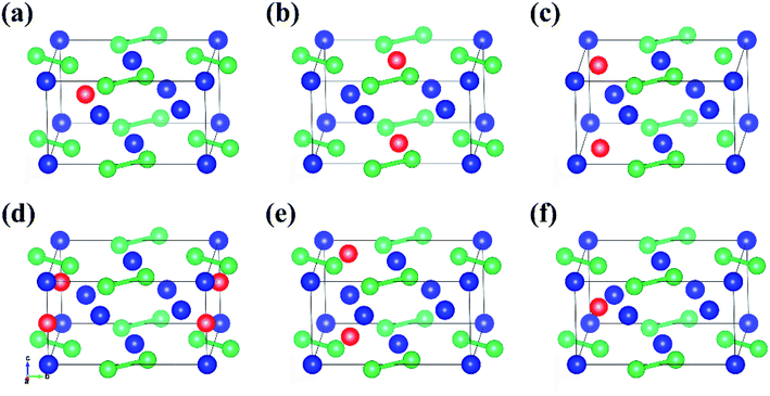
Nuclear fuel with enhanced safety requires excellent mechanical property and high thermal conductivity under harsh conditions. The research on the mechanical anisotropy and thermodynamic properties of Al-alloyed U3Si2 ternary compounds have not been studied so far. In this work, including one Si-vacancy position, two U-vacancy positions and three interstitial sites with all different symmetries are selected as Al atom alloying sites. The atomic coordinates for three interstitial sites are (0, 0, 0.5), (0.319, 0.181, 0), (0.611, 0.111, 0.5). Through first-principles calculation of the phonon spectrum, the dynamically stable structures are screened out. The mechanical anisotropy as well as thermodynamic properties of U3Si2–Al ternary compounds are studied. This work will serve as a reference for the design of a new generation of ATF and the establishment of the U–Si–Al ternary phase diagram.
2 Method
The theoretical calculations in this paper are based on density functional theory,23,24 using Vienna ab initio simulation package (VASP)25 to perform first-principles calculations. During the calculation process, the electron wave function uses the plane wave super-soft pseudopotential method.26 Generalized Gradient Approximation (GGA) combined with Perdew–Burke–Ernzerhof (PBE) functional27 is employed to describe the exchange–correlation interactions between electrons. Since the 5f electron of U atom has a strong local Coulomb repulsion, the spin polarized PBE+U28 method is used to eliminate this correlation.In this work, the optimized total energy cutoff energy of the original unit cell was set to 500 eV, and the k-point meshes were constructed using the Monkhorst–Pack scheme. The 9 × 9 × 9 k-point mesh was used for the primitive cell for Brillouin zone sampling.29 The structural optimization were under the conditions that the total energy difference between two iterations was less than 10–5 eV and the force on the atom was less than 0.01 eV Å−1. The elastic properties in this article are achieved by an effective stress–strain method.30 Periodic boundary conditions were adopted in this work.
The theoretical phonon spectrum was obtained using the Phonopy package.31 The lattice thermal conductivity is obtained by using phono3py,32 where the phonon lattice thermal conductivity and phonon relaxation time were simulated by using the finite displacement method.33 The formula for lattice thermal conductivity is as follow eqn (1):
 | (1) |
3 Results and discussion
3.1 Structural parameters
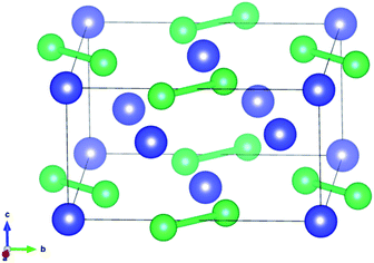
U3Si2 belonging to the p4/mm space group as a typical tetragonal crystal system at 0 K contains ten atoms in each primitive unit cell, as shown in Fig. 1. The PBE and PBE+U methods were used when optimizing the original structure.The results shown in previous literatures35,36 are also listed in Table 1 for reference. As shown in Table 1, the lattice constant a (a = b) is 7.24 Å, the value of c is 3.90 Å, and the volume is 204.43 Å3 for primitive U3Si2 by using the method of PBE, which have obvious deviations from the previous experimental and calculated results. When using the PBE+U method to optimize the original U3Si2, the calculation results show that the lattice constant a and c reach 7.39 Å and 3.95 Å, respectively; and the volume is 215.72 Å3. The structural parameters calculated by the PBE+U method are closer to the experimental and calculated values, which proves that the calculation method of PBE+U is effective. Further, the non-spin polarized (non-SP) DFT + U calculations have also been performed to make comparisons with spin polarized (SP) calculations; and the results are listed in Table 1. It can be seen that the results obtained from the spin polarized DFT + U are consistent with the reported experimental results. Therefore, in the following calculations, the PBE+U method is adopted and U = 2.0 with spin polarized (where the magnetic moments for U, Si and Al atoms are 2.46 μB per atom, −0.025 μB per atom, and −0.20 μB per atom, respectively) is chosen as the calculation parameter.
3.2 Structural design
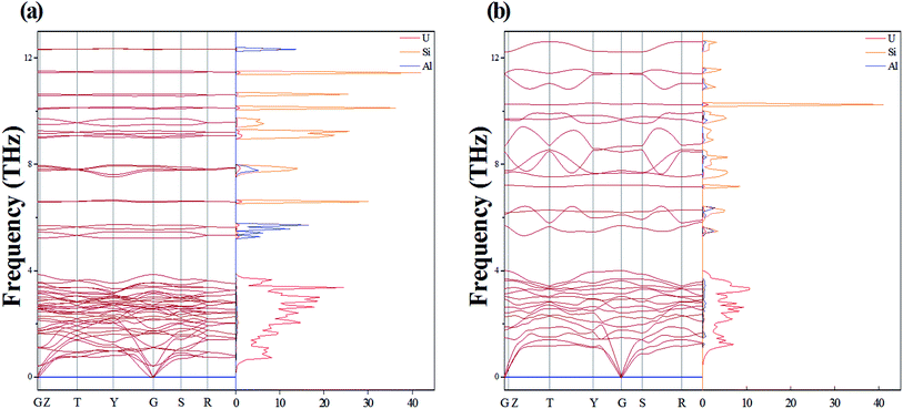
One Al atom substitutes U or Si positions of U3Si2 and the three resulting structures named sub-U2.5Si2Al0.5(I), sub-U2.5Si2Al0.5(II) and sub-U3Si1.5Al0.5 are shown in Fig. 2(a)–(c). The three configurations that one Al atom staying in three different interstitial sites of U3Si2 are shown in Fig. 2(d)–(f), which are named int-U3Si2Al0.5(I), int-U3Si2Al0.5(II) and int-U3Si2Al0.5(III). These six defect positions shown in Fig. 2 are based on the optimized structure of the initial unit cell of U3Si2. For a crystal structure with dynamic stability determined by phonons, the value of its phonon dispersion curve must be a real number.31By calculating the phonon dispersion curves, two stable structures are obtained. Fig. 3(a) and Fig. 3(b) are the phonon dispersion curves of sub-U3Si1.5Al0.5 and sub-U2.5Si2Al0.5(I), respectively. The phonon dispersion curves of the remaining four are unstable structures due to the appearance of obvious imaginary frequency. As shown in Fig. 3, for sub-U3Si1.5Al0.5 and sub-U2.5Si2Al0.5(I), these phonon dispersion curves without imaginary frequency. In order to further determine the dynamic stability of the two structures, the corresponding phonon density of states is also calculated in Fig. 3. The phonon density of states is shown in Fig. 3 without imaginary frequency, implying that the optimized structure of sub-U3Si1.5Al0.5 and sub-U2.5Si2Al0.5(I) are dynamically stable. In the following calculations, these two stable structures are used as research target structures.
3.3 Mechanical properties
For nuclear fuels, the mechanical anisotropy might cause cracks under the actions of applied stress. In this section, the toughness of the material is firstly estimated through bulk modulus (B) and shear modulus (G), where B can reflect the incompressibility of the material, and the G can estimate the degree of deformation caused by shear force. The mechanical anisotropy of the material is then evaluated through the three-position Young's modulus diagram and Au. The B and G of U3Si2, U3Si1.5Al0.5 and sub-U2.5Si2Al0.5(I) are calculated in this work, as shown in Table 2, where U3Si2 bulk modulus and shear modulus are 87.69 GPa and 65.37 GPa, which are basically consistent with the calculation results of Wang et al.12 and Chattaraj et al.37 In comparison, both of the B and G values for sub-U3Si1.5Al0.5 and sub-U2.5Si2Al0.5(I) are lower than the values of U3Si2 to a certain extent, indicating that their incompressibility and deformation resistance are weaker than U3Si2.As proposed by Pugh et al.38 the ductility of a material can be defined through the value of B/G; and 1.75 is specified as a critical value. The materials with their values below 1.75 are treated as brittle, while the ones with values above 1.75 are treated as ductile. The data in Table 2 show that U3Si2, sub-U3Si1.5Al0.5 and sub-U2.5Si2Al0.5(I) are all brittle materials, but the B/G values of sub-U3Si1.5Al0.5 and sub-U2.5Si2Al0.5(I) after alloying are significant increase and very close to 1.75. Therefore, we can understand that alloying could improve the toughness of the material. In addition, Poisson's ratio is also calculated using the following eqn (2):
 | (2) |
According to Frantsevich's theory, the value of σ could also be used as a criterion for judging whether the material has ductility, and 0.26 is defined as the critical value.39 The calculation results of U3Si2, sub-U3Si1.5Al0.5 and sub-U2.5Si2Al0.5(I) σ are shown in Table 2. The σ values of the three compounds are all less than or equal to 0.26, indicating that they are all brittle materials. However, sub-U3Si1.5Al0.5 and sub-U2.5Si2Al0.5(I) have a significant increase compared with U3Si2, which is consistence to the conclusion of B/G.
The anisotropy of elasticity could be characterized by anisotropy index Au, which was proposed by Ranganathan and Ostoja-Starzewski40 and is derived by eqn (3):
 | (3) |
| BV = [C11 + C22 + C33 + 2(C12 + C13 + C23)]/9 | (4) |
| GV = [(C11 + C22 + C33) − (C12 + C13 + C23) + 3(C44 + C55 + C66)]/15 | (5) |
| BR = 1/[S11 + S22 + S33 + 2(S12 + S13 + S23)] | (6) |
| GR = 15/[4(S11 + S22 + S33) − 4(S12 + S13 + S23) + 3(S44 + S55 + S66)] | (7) |
For the tetragonal structure, the same variables from shear modulus, as well as the variables from bulk modulus can be calculated by eqn (8)–(11):42,43
| BV = [2(C11 + C12) + 4C13 + C33]/9 | (8) |
| GV = (M + 3C11 − 3C12 + 12C44 + 6C66)/30 | (9) |
| BR = C11 + C12 + 2C33 − 4C13/C11 + C12 + 2C33 − 4C13 | (10) |
| GR = 15/[(18BV)/C2 + 6/(C11 − C12) + 6/C44 + 3/C66] | (11) |
Sij is the elastic compliance constant, and Cij is the elastic constant. From the Au value in Table 2, it can be concluded that U3Si2 has the lowest anisotropy is, followed by sub-U3Si1.5Al0.5, and finally sub-U2.5Si2Al0.5(I).
Next, the three-dimensional Young's modulus diagram is used to visually explore the anisotropy of elasticity. For tetragonal and orthogonal structures, the three-dimensional Young's modulus is expressed using eqn (12) and (13):44,45
 | (12) |
 | (13) |
The isotropic materials would display a three-dimensional spherical structure; otherwise, the solid material is anisotropic one. The larger the deviation to spherical structure, the higher the anisotropy. Fig. 4 shows the three-dimensional Young's modulus calculated from the above formula. The curved surface for U3Si2 is close to a circle, and its Au value is 0.13; while the Au values of sub-U3Si1.5Al0.5 and sub-U2.5Si2Al0.5(I) are 0.32 and 1.27 respectively, indicating that U3Si2 has the strongest isotropy, followed by sub-U3Si1.5Al0.5, and the most anisotropy belongs to sub-U2.5Si2Al0.5(I).
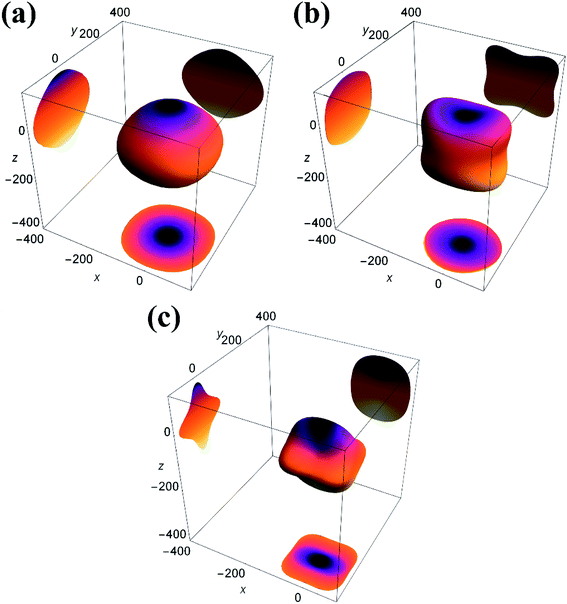 | ||
| Fig. 4 3D Young's modulus (E) and projections of the 3D Young's modulus of (a) U3Si2 (b) sub-U3Si1.5Al0.5 (c) sub-U2.5Si2Al0.55(I). | ||
In order to further study the anisotropy of elasticity, 2D plane projections along the directions of [100], [010] and [001] have also been added into Fig. 4. For U3Si2, the maximum Young's modulus is 150 GPa, while sub-U3Si1.5Al0.5 is 130Gpa, and sub-U2.5Si2Al0.5(I) is 110 GPa. Therefore, it can be concluded that the sub-U3Si1.5Al0.5 still maintains high isotropy, and the Young's modulus of the structure does not change much, while the sub-U2.5Si2Al0.5(I) shows out of the strong anisotropy, the Young's modulus decreases significantly. The conclusions are consistent with the result determined by the Au value.
3.4 Thermal conductivity
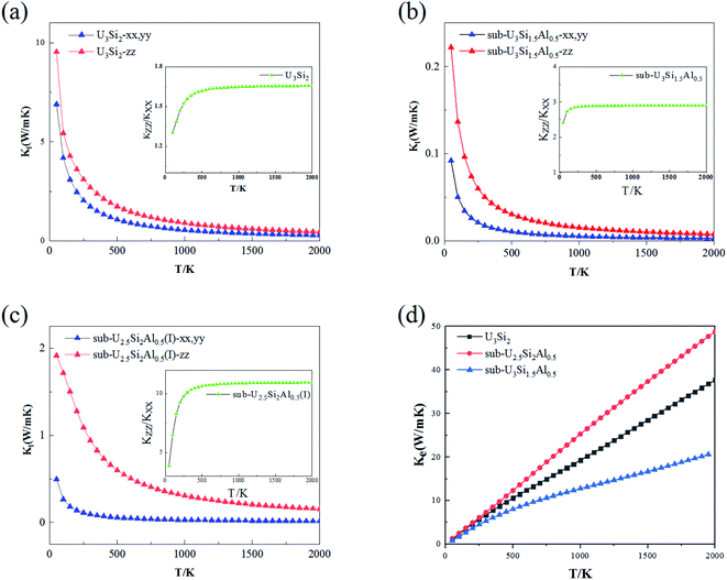
The thermal conductivity is an important property of nuclear fuel, since it determines the surface and centerline temperature of nuclear fuel during operation, as well as its maximum allowable direct heating rate. Phonons play an important role in dynamic behavior and thermal properties. The thermal conductivity of U3Si2 mainly comes from the contribution of phonons and electrons due to its metallic nature. In this section, we employ first-principle calculations to derive the phonon–phonon interaction strength. By solving the linearized Boltzmann transport equation, the lattice thermal conductivity in different directions can be accurately calculated; where the electronic transport properties are approximated with the relaxation time τ = 0.68 × 10⁻¹⁴ s evaluated using ρ at 300 K obtained from experiments.46The anisotropic lattice thermal conductivity of U3Si2, sub-U3Si1.5Al0.5 and sub-U2.5Si2Al0.5(I) is calculated, as shown in Fig. 5(a–c), the inset is the curve of Kzz/Kxx with temperature. It is worth noting that smaller values of Kl in the x- and z-directions have recently been reported in ref. 47 with the consideration of the occupation matrix control (OMC). In comparison, the results obtained within this work using VASP with the consideration of the U ramping method; and this is known as a source of discrepancies in DFT + U calculations. As shown in the Fig. 5(a–c), as the temperature increases, the lattice thermal conductivity of the three compounds decreases drastically until it becomes flat. This is because the scattering between phonons and phonons strengthens with the increase of temperature. It can be seen from the illustration that the Kzz/Kxx of U3Si2 is 1.3 at 50 K. As the temperature increases, it rises to a saturation value of 1.65 at about 300 K, and then gradually stabilizes. The general trends of sub-U3Si1.5Al0.5 and sub-U2.5Si2Al0.5(I) are similar to those of U3Si2. The same, but the saturation value is different, the former is 2.95 and the latter is 10.5. Therefore, we understand that through alloying, the lattice thermal conductivity still maintains a high isotropy as the temperature increases. This isotope of the thermal conductivity of the phonon is caused by the dispersion phase space and the similar group velocities in different directions.48 Fig. 5(d) shows the calculated electronic thermal conductivity (Ke/τ), U3Si2, sub-U3Si1.5Al0.5and sub-U2.5Si2Al0.5(I); and it can be seen from the figure that the electronic thermal conductivity of the three compounds all increase linearly with the increase of temperature. In addition, for the compound of sub-U3Si1.5Al0.5 configuration, the increase rate of the electronic thermal conductivity with the increase of temperature is lower than that of U3Si2, while the increase rate of the compound of sub-U2.5Si2Al0.5(I) configuration is higher than that of U3Si2.
4 Conclusion
This paper studies the mechanical and thermal properties of Al-alloyed U3Si2 nuclear fuels on the basis of first principles. Through the phonon dispersion curve, two kinetic stable structures sub-U3Si1.5Al0.5 and sub-U2.5Si2Al0.5(I) are screened out. We found that the toughness of the two compounds after alloying were significantly improved compared to U3Si2. The three-dimensional Young's modulus show that, the sub-U3Si1.5Al0.5 formed by Al alloying in U3Si2 maintains a higher mechanical isotropy, while sub-U2.5Si2Al0.5(I) shows higher mechanical anisotropy, Which are consistent with the value of Au. The calculation result shows that the lattice thermal conductivity of sub-U3Si1.5Al0.5 and sub-U2.5Si2Al0.5(I) after Al alloying exhibits high isotropy as the temperature increases.Conflicts of interest
There are no conflicts to declare.Acknowledgements
The authors acknowledge the financial support of National Natural Science Foundation of China (Grant no. 51872302, 21875271), National Key Research and Development Program of China (No. 2016YFB0700100), Key Research and Development Program of Zhejiang Province (Grant no. 2019C01060).References
- S. J. Zinkle and G. Was, Materials challenges in nuclear energy, Acta Mater., 2013, 61(3), 735–758 CrossRef CAS.
- T. Kaloni, et al., DFT+U approach on the electronic and thermal properties of hypostoichiometric UO2, Ann. Nucl. Energy, 2020, 144, 107511 CrossRef CAS.
- E. Torres and T. Kaloni, Projector augmented-wave pseudopotentials for uranium-based compounds, Comput. Mater. Sci., 2020, 171, 109237 CrossRef CAS.
- E. Torres, et al., A comparative analysis of the phonon properties in UO2 using the Boltzmann transport equation coupled with DFT+U and empirical potentials, Comput. Mater. Sci., 2020, 177, 109594 CrossRef CAS.
- J. Roleček, et al., A feasibility study of using CeO2 as a surrogate material during the investigation of UO2 thermal conductivity enhancement, Adv. Appl. Ceram., 2017, 116(3), 123–131 CrossRef.
- M. Kurata, Research and development methodology for practical use of accident tolerant fuel in light water reactors, Nucl. Eng. Technol., 2016, 48(1), 26–32 CrossRef CAS.
- Z. Karoutas, et al., The maturing of nuclear fuel: Past to Accident Tolerant Fuel, Prog. Nucl. Energy, 2018, 102, 68–78 CrossRef CAS.
- S. J. Zinkle, et al., Accident tolerant fuels for LWRs: A perspective, J. Nucl. Mater., 2014, 448(1–3), 374–379 CrossRef CAS.
- D. Kawasaki, et al., Deterministic performance assessment for a conceptual repository for low-and intermediate-level wastes in Korea, Nucl. Technol., 2006, 154(3), 374–388 CrossRef CAS.
- J. White, et al., Thermophysical properties of U3Si to 1150 K, J. Nucl. Mater., 2014, 452(1–3), 304–310 CrossRef CAS.
- M. Finlay, G. Hofman and J. Snelgrove, Irradiation behaviour of uranium silicide compounds, J. Nucl. Mater., 2004, 325(2–3), 118–128 CrossRef CAS.
- T. Wang, et al., First-principles investigations on the electronic structures of U3Si2, J. Nucl. Mater., 2016, 469, 194–199 CrossRef CAS.
- D. Andersson, et al., Density functional theory calculations of self-and Xe diffusion in U3Si2, J. Nucl. Mater., 2019, 515, 312–325 CrossRef CAS.
- J. L. Snelgrove, et al., Development of very-high-density low-enriched-uranium fuels, Nucl. Eng. Des., 1997, 178(1), 119–126 CrossRef CAS.
- E. S. Wood, J. T. White and A. T. Nelson, The effect of aluminum additions on the oxidation resistance of U3Si2, J. Nucl. Mater., 2017, 489, 84–90 CrossRef CAS.
- J. Marín, et al., Synthesis and clad interaction study of U3Si2 powders dispersed in an aluminum matrix, J. Nucl. Mater., 1996, 228(1), 61–67 CrossRef.
- X.-S. Wang and Y. Xu, Experiments, characterizations and analysis of a U3Si2–Al dispersion fuel plate with sandwich structure, J. Nucl. Mater., 2004, 328(2–3), 243–248 CrossRef CAS.
- J. Gan, et al., Microstructure of the irradiated U3Si2/Al silicide dispersion fuel, J. Nucl. Mater., 2011, 419(1–3), 97–104 CrossRef CAS.
- D. Rabin, et al., Thermodynamic modeling of Al–U–X (X= Si, Zr), J. Nucl. Mater., 2015, 464, 170–184 CrossRef CAS.
- V. Zenou, et al., Ordered U (Al, Si)3 phase: Structure and bonding, J. Alloys Compd., 2017, 690, 884–889 CrossRef CAS.
- M. Mirandou, et al., Study of the Interaction Between U3Si2/Al in Dispersion Plates at the End of the Fabrication Process, Nucl. Technol., 2017, 199(1), 96–102 CrossRef.
- L. Suparlina, T. Surbakti and T. Sembiring, Safety analysis of Test Fuel Elements U3Si2-Al 4.8 gU/cc and 5.2 gU/CC AT RSG-GAS Reactor, in Research Reactors: Safe Management and Effective Utilization. Summary of an International Conference, Companion CD-ROM, 2017 Search PubMed.
- G. Kresse and J. Hafner, Ab initio molecular-dynamics simulation of the liquid-metal–amorphous-semiconductor transition in germanium, Phys. Rev. B, 1994, 49(20), 14251 CrossRef CAS.
- G. Kresse and J. Furthmüller, Efficiency of ab-initio total energy calculations for metals and semiconductors using a plane-wave basis set, Comput. Mater. Sci., 1996, 6(1), 15–50 CrossRef CAS.
- G. Kresse and J. Hafner, Ab initio molecular dynamics for open-shell transition metals, Phys. Rev. B: Condens. Matter Mater. Phys., 1993, 48(17), 13115 CrossRef CAS.
- D. Vanderbilt, Soft self-consistent pseudopotentials in a generalized eigenvalue formalism, Phys. Rev. B: Condens. Matter Mater. Phys., 1990, 41(11), 7892 CrossRef.
- J. P. Perdew, K. Burke and M. Ernzerhof, Generalized gradient approximation made simple, Phys. Rev. Lett., 1996, 77(18), 3865 CrossRef CAS.
- S. Dudarev, et al., Electron-energy-loss spectra and the structural stability of nickel oxide: An LSDA+ U study, Phys. Rev. B: Condens. Matter Mater. Phys., 1998, 57(3), 1505 CrossRef CAS.
- H. J. Monkhorst and J. D. Pack, Special points for Brillouin-zone integrations, Phys. Rev. B: Condens. Matter Mater. Phys., 1976, 13(12), 5188 CrossRef.
- A. Togo, F. Oba and I. Tanaka, First-principles calculations of the ferroelastic transition between rutile-type and CaCl2-type SiO2 at high pressures, Phys. Rev. B, 2008, 78(13), 134106 CrossRef.
- A. Togo and I. Tanaka, First principles phonon calculations in materials science, Scr. Mater., 2015, 108, 1–5 CrossRef CAS.
- A. Togo, L. Chaput and I. Tanaka, Distributions of phonon lifetimes in Brillouin zones, Phys. Rev. B, 2015, 91(9), 094306 CrossRef.
- K. Parlinski, Z. Li and Y. Kawazoe, First-principles determination of the soft mode in cubic ZrO2, Phys. Rev. Lett., 1997, 78(21), 4063 CrossRef CAS.
- G. Madsen, K. Schwarz and D. Singh, BoltzTraP. A code for calculating band-structure dependent quantities, Comput. Phys. Commun., 2006, 175(1), 67–71 CrossRef CAS.
- K. Srinivasu, B. Modak and T. K. Ghanty, Electronic structure and thermophysical properties of U3Si2: A systematic first principle study, J. Nucl. Mater., 2018, 510, 360–365 CrossRef CAS.
- K. Remschnig, et al., Structural chemistry and magnetic behavior of binary uranium silicides, J. Solid State Chem., 1992, 97(2), 391–399 CrossRef CAS.
- D. Chattaraj and C. Majumder, Structural, electronic, elastic, vibrational and thermodynamic properties of U3Si2: A comprehensive study using DFT, J. Alloys Compd., 2018, 732, 160–166 CrossRef CAS.
- S. Pugh, XCII. Relations between the elastic moduli and the plastic properties of polycrystalline pure metals, London, Edinburgh Dublin Philos. Mag. J. Sci., 1954, 45(367), 823–843 CrossRef CAS.
- I. N. Frantsevich, F. F. Voronov and S. A. Bakuta, Elastic Constants and Elastic Moduli of Metals and Nonmetals: A Handbook, Naukova Dumka, Kiev, 1982 Search PubMed.
- J. Chen, et al., Elastic anisotropy and thermodynamics properties of BiCu2PO6, BiZn2PO6 and BiPb2PO6 ceramics materials from first-principles calculations, Ceram. Int., 2020, 46(7), 8575–8581 CrossRef CAS.
- R. Hill, A general theory of uniqueness and stability in elastic-plastic solids, J. Mech. Phys. Solids, 1958, 6(3), 236–249 CrossRef.
- A. Reuss, Calculation of the flow limits of mixed crystals on the basis of the plasticity of monocrystals, Z. Angew. Math. Mech., 1929, 9, 49–58 CrossRef CAS.
- E. W. Kammer, T. Pardue and H. Frissel, A determination of the elastic constants for beta-quartz, J. Appl. Phys., 1948, 19(3), 265–270 CrossRef CAS.
- W. Bao, D. Liu and Y. Duan, A first-principles prediction of anisotropic elasticity and thermal properties of potential superhard WB3, Ceram. Int., 2018, 44(12), 14053–14062 CrossRef CAS.
- D. Shi, et al., Defective structures in FeCrAl alloys from first principles calculations, Jpn. J. Appl. Phys., 2020, 59(4), 046003 CrossRef CAS.
- D. J. Antonio, et al., Thermal and transport properties of U3Si2, J. Nucl. Mater., 2018, 508, 154–158 CrossRef CAS.
- T. Kaloni and E. Torres, Thermal and mechanical properties of U3Si2: A combined ab-initio and molecular dynamics study, J. Nucl. Mater., 2020, 152090 CrossRef CAS.
- H. Peng, N. Kioussis and D. A. Stewart, Anisotropic lattice thermal conductivity in chiral tellurium from first principles, Appl. Phys. Lett., 2015, 107(25), 251904 CrossRef.
| This journal is © The Royal Society of Chemistry 2020 |

