 Open Access Article
Bismuthene nanosheets produced by ionic liquid assisted grinding exfoliation and their use for oxygen reduction reaction†
Manila Ozhukil Valappil‡
 ab,
Abhijit Ganguly‡
 a,
John Bensonc,
Vijayamohanan K. Pillaid,
Subbiah Alwarappan
 b and
Pagona Papakonstantinou
 *a
*a
aEngineering Research Institute, School of Engineering, Ulster University, Newtownabbey BT37 0QB, UK. E-mail: p.papakonstinou@ulster.ac.uk
bElectrodics and Electrocatalysis Division, CSIR-Central Electrochemical Research Institute, Karaikudi, Tamil Nadu 630003, India
c2-DTech Ltd, Core Technology Facility, 46 Grafton St, Manchester M13 9NT, UK
dDepartment of Chemistry, Indian Institute of Science Education and Research, Tirupati, India
First published on 9th December 2020
Abstract
We report the simple synthesis of bismuthene nanosheets (BiNS) by ionic liquid assisted grinding exfoliation, followed by size selection sequential centrifugation steps for the first time. The exfoliation process results in the formation of self-assembled spherule-like superstructures with abundant edge sites, which are able to catalyze the oxygen reduction reaction (ORR) via a two-electron pathway, with a higher efficiency than the bulk Bismuth. We rationalize the enhanced ORR activity of the BiNS to: (i) the presence of 1 dimensional topological edge states, which provide strong conduction channels for electron hopping between the bismuth layers and (ii) the more active role of edge sites in facilitating O2 adsorption and dissociation of O–O bonds compared to the basal plane. The present study provides a pathway for employing 2D topological insulators as a new class of electrocatalysts for clean energy applications.
Introduction
Atomic two-dimensional (2D) layers have been captivating researchers' interest ever since the discovery of graphene. Most recently, research efforts have been focused on heavy pnictogens, such as arsenene, antimonene, and bismuthene, which have emerged as new members of the 2D family.1 Among the 2D pnictogens members, bismuthene can be distinguished from other heavy metals, since it possesses a high volumetric capacity (3000 mA h L−1), environmental benignity and unusually low toxicity. Its bulk counterpart bismuth (Bi) exhibits metallicity and consists of stacked layers with a buckled rhombohedral crystal structure. This permits Bi to be potentially exfoliated to its 2D single or a few-layers with an enlarged surface area, making it usable for electrochemical based applications. In fact, bismuthene nanosheets (BiNS) have recently been investigated in electrocatalytic CO2![[thin space (1/6-em)]](https://www.rsc.org/images/entities/char_2009.gif) 2,3 and N2 reduction reactions,4 and as anode material for Na and K ion batteries,5,6 demonstrating promising performance. Bismuthene multi-layered nanosheets have been synthesized recently with state-of-the-art synthesis methodologies, including, shear exfoliation in liquids,7 ultra-sonic exfoliation,8 electrochemical exfoliation3,6 of Bi crystals and electro-reduction of Bi precursors.2,9 Nevertheless, the fabrication of a few-layer BiNS via scalable methods is highly challenging.
2,3 and N2 reduction reactions,4 and as anode material for Na and K ion batteries,5,6 demonstrating promising performance. Bismuthene multi-layered nanosheets have been synthesized recently with state-of-the-art synthesis methodologies, including, shear exfoliation in liquids,7 ultra-sonic exfoliation,8 electrochemical exfoliation3,6 of Bi crystals and electro-reduction of Bi precursors.2,9 Nevertheless, the fabrication of a few-layer BiNS via scalable methods is highly challenging.
Oxygen reduction reaction (ORR) plays a crucial role for commercial development of clean renewable energy storage and conversion systems such as metal–air batteries and low-temperature fuel cells (four-electron (4e−) reduction pathway) and also for generation of hydrogen peroxide (2e− pathway).
The development of non-precious metal catalysts with either 4e− ORR or 2e− ORR has become a main focus of research regarding these applications.10,11 However, there have not been any dedicated attempts to explore the performance of BiNS as an ORR catalyst. In light of all these gaps in the reported literature, we report here an approach to prepare ultrathin BiNS via an ionic liquid assisted grinding exfoliation process followed by sequential centrifugation steps to separate various sizes. Remarkably we noticed a spherules self-assembled morphology, upon evaporation of the solvent and found that these ultrathin self-assembled nanosheets of bismuthene act as an efficient ORR electrocatalyst. We attribute the enhanced electrocatalytic activity of BiNS to the abundance of electron conducting channels at the edges, arising from the 2D topological insulator nature of bismuthene, and to the more active role of edges on adsorbing and dissociating O2 compared to the bulk Bi.
Results and discussion
The exfoliation process involves grinding of bulk bismuth powder with a small amount of ionic liquid to produce a gel followed by removal of the ionic liquid and sequential centrifugation. Bi powder (∼100 mesh) was ground in an agate mortar grinder. The grinding was carried out for 60 hours by mixing room temperature ionic liquid (1-butyl-3-methylimidazolium hexafluorophosphate, BMIMPF6) and Bi powder in a ratio of 1![[thin space (1/6-em)]](https://www.rsc.org/images/entities/char_2009.gif) :
:![[thin space (1/6-em)]](https://www.rsc.org/images/entities/char_2009.gif) 2. The progress of exfoliation was indicated by the formation of a gelatinous material. The resulting gel was further subjected to removal of ionic liquid by washing three times with DMF–acetone mixture (1
2. The progress of exfoliation was indicated by the formation of a gelatinous material. The resulting gel was further subjected to removal of ionic liquid by washing three times with DMF–acetone mixture (1![[thin space (1/6-em)]](https://www.rsc.org/images/entities/char_2009.gif) :
:![[thin space (1/6-em)]](https://www.rsc.org/images/entities/char_2009.gif) 3). The purified product was then size separated by sequential centrifugation at 0.5k, 1k and 3k revolutions per minute (rpm) as described in our previous works.12–15 The products were then vacuum dried and further used for characterisation. Isolated products were labelled as BiNS Xk, where Xk represents the centrifugation speed in rpm.
3). The purified product was then size separated by sequential centrifugation at 0.5k, 1k and 3k revolutions per minute (rpm) as described in our previous works.12–15 The products were then vacuum dried and further used for characterisation. Isolated products were labelled as BiNS Xk, where Xk represents the centrifugation speed in rpm.
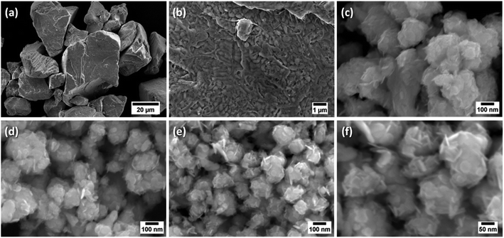
The morphological analysis of the size selected materials was analysed using Field-Emission Scanning Electron Microscopy (FESEM) as shown in Fig. 1. The morphology of bulk bismuth metal was also examined for comparison. Bulk Bi consists of large and thick chunks (Fig. 1a) of approximate size of 6–60 μm with thickness of 2–40 μm, as estimated from the statistical analysis of the FESEM images (Fig. S1a for particle size and Fig. S1b for thickness histograms, presented in ESI†). However, a closer view on the surface of those chunks revealed an island-like arrangement with a lateral size <0.3 μm (Fig. 1b).
Exfoliation and subsequent centrifugation (from 0.5k to 3k rpm) led to the formation of agglomerates of progressively smaller size and thickness with increasing centrifugation speed, as observed from Fig. 1c to e and evidenced from the respective statistical analysis (Fig. S1†). In fact, the agglomerates consist of 2D bismuthene nanosheets, which are intertwined to form self-assembled flower-like or spherules-like superstructure with porous morphology (Fig. 1c–f). The production yield of this self-assembled process is almost 100%, and the statistical analysis has shown that the diameter of the spherules (peak values ranging from 165 to 88 nm, Fig. S1a†) as well as the nanosheet-thickness (9 to 5 nm, Fig. S1b†) can be tuned by varying the flake size with increasing centrifugation speeds from 0.5k to 3k rpm (Fig. 1c–f). The small nanosheet size at 3k rpm (minimum value achieved of ∼20 nm with thickness of ∼2 nm), shown in Fig. 1e and f, arises mainly from the compressive and shear forces exerted during the grinding process.
It is worth noting that due to its soft metallic nature, the mechanical breaking point of Bi is much smaller than that of graphene, leading to the high yield of nanosheet with small lateral size. It is emphasized that formation of spherules-like superstructures assembled by intertwining ultrathin nanosheets, at different angles, has not been observed in our earlier studies with other 2D layered nanomaterials like graphene,12 MoS2![[thin space (1/6-em)]](https://www.rsc.org/images/entities/char_2009.gif) 13 or WS2
13 or WS2![[thin space (1/6-em)]](https://www.rsc.org/images/entities/char_2009.gif) 14 nanosheets produced by the same exfoliation approach. BiNS in powder form, produced via oven drying of the centrifugation product, and subsequently redispersed in various solvents (acetone, DMF, ethanol, hexane) and drop dried under in infra-red lamp, displayed a similar aggregation without showing any solvent dependency, as evidenced from the FESEM observations in Fig. S2.† It is believed that the self-assembly arises from convection driven evaporation dynamics of the solvent upon the drying process.16 The drying process is regulated by BiNS nanosheet interactions, packing constraints, mass and heat transfer during drying, together with kinetic and thermodynamic factors. It is known, that evaporating sessile droplets loaded with colloidal nanoparticles from volatile solvent can generate a wealth of ordered architectures that arise from evaporation-driven fluid flow. This self-assembly is a complex process that is controlled by the nanoparticle (physical and chemical properties of nanoparticle suspension, size, geometry, concentration), solvent, droplet geometry, substrate hydrophobicity, and evaporation kinetics. Previous work17 has indeed demonstrated that the convective evaporation-induced assembly process can be strongly influenced by convective fluid particle transport, including the Marangoni flow, which arises from temperature and concentration gradients.17–20 The self-assembled spherules organisation of bismuth nanosheets has not been reported before and demands further in-depth analysis. Importantly, the spherules-like superstructure with porous morphology could provide highly accessible surfaces, which would be beneficial for high ion transport essential for energy storage devices.
14 nanosheets produced by the same exfoliation approach. BiNS in powder form, produced via oven drying of the centrifugation product, and subsequently redispersed in various solvents (acetone, DMF, ethanol, hexane) and drop dried under in infra-red lamp, displayed a similar aggregation without showing any solvent dependency, as evidenced from the FESEM observations in Fig. S2.† It is believed that the self-assembly arises from convection driven evaporation dynamics of the solvent upon the drying process.16 The drying process is regulated by BiNS nanosheet interactions, packing constraints, mass and heat transfer during drying, together with kinetic and thermodynamic factors. It is known, that evaporating sessile droplets loaded with colloidal nanoparticles from volatile solvent can generate a wealth of ordered architectures that arise from evaporation-driven fluid flow. This self-assembly is a complex process that is controlled by the nanoparticle (physical and chemical properties of nanoparticle suspension, size, geometry, concentration), solvent, droplet geometry, substrate hydrophobicity, and evaporation kinetics. Previous work17 has indeed demonstrated that the convective evaporation-induced assembly process can be strongly influenced by convective fluid particle transport, including the Marangoni flow, which arises from temperature and concentration gradients.17–20 The self-assembled spherules organisation of bismuth nanosheets has not been reported before and demands further in-depth analysis. Importantly, the spherules-like superstructure with porous morphology could provide highly accessible surfaces, which would be beneficial for high ion transport essential for energy storage devices.
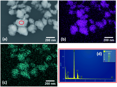
The elemental composition of the as exfoliated BiNS was analysed using Energy-Dispersive X-ray analysis (EDAX), elemental mapping. Elemental mapping of BiNS 3k (SEM image shown in Fig. 2a) confirmed a uniform distribution of bismuth element (Fig. 2b). Trace amounts of oxygen was also noted, as shown in (Fig. 2c), revealing the presence of surface oxides. EDAX spectrum of BiNS 3k sheets confirmed the presence of Bi and oxygen elements (Fig. 2d) as well as a small amount of carbon and nitrogen originating from the DMF solvent.
Furthermore, the chemical environment of the as synthesised BiNS was analysed using X-ray photoelectron spectroscopy (XPS). The XPS survey scans confirmed the similarity in elemental composition between bulk Bi and BiNS, contributed mainly by Bi element (Fig. S3†). A considerably intense O 1s signal suggested the presence of oxide phases, which originated from the starting bulk Bi material. A carbon signal was also observed, originating from adventitious contamination, adsorbed on the sample's surface. Comparative Bi 4f, Bi 5d and O 1s core level spectra of bulk Bi and BiNS 3k are shown in Fig. 3. Two pairs of peaks with energy difference of 5.31 eV (Bi 4f5/2 164.13 eV; Bi 4f7/2, 158.82 eV) and 3.02 eVs (Bi 5d3/2, 28.83 eV; Bi 5d5/2, 25.81 eV) due to the spin-orbital splitting were identified from Bi 4f (Fig. 3b) and 5d core level spectra (Fig. 3a) respectively of bulk bismuth.21 BiNS 3k centrifugation products exhibited nearly the same binding energies for well-defined spin-coupled doublets with same energy difference as those of bulk crystal (Table S1†). In addition, no additional or enhanced sub-bands from bismuth oxides5 were detected, in the BiNS, indicating that the exfoliation process does not introduce any oxidation. Actually, BiNS 3k nanosheets exhibited a smaller contribution from BiOx (6.3 at%) (Fig. 3a), compared to bulk Bi (11.2 at%).
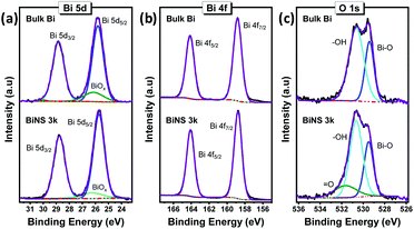 | ||
| Fig. 3 High resolution XP spectra of bulk Bi (top) and bismuthene nanosheets (BiNS 3k, bottom plots): (a) Bi 5d, (b) Bi 4f and (c) O 1s spectra. | ||
Similarly, the deconvoluted O 1s spectra of both the bulk and exfoliated materials (Fig. 3c) showed the presence of a lower binding energy peak corresponding to bismuth oxide (Bi–O), along with the higher binding energy signals attributed to the surface-bound hydroxyl groups (–OH) or other singly bonded oxygen groups.21 In agreement with the Bi 5d core level spectra, the exfoliated BiNS exhibited a lower Bi–O contribution (27 at%), relative to its bulk counterpart (33 at%). On the contrary, the relatively higher peak intensity of the hydroxyl moieties and pronounced appearance of doubly bonded oxygen groups (![[double bond, length as m-dash]](https://www.rsc.org/images/entities/char_e001.gif) O) is associated with the considerably higher surface area available for BiNS.
O) is associated with the considerably higher surface area available for BiNS.
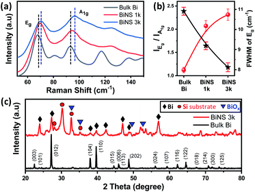
Raman spectroscopy is an important tool for studying the exfoliation of 2D layered materials. Fig. 4a and S4† show the comparative Raman spectra of exfoliated BiNS collected at the centrifugation speeds of 1k and 3k rpm together with those of bulk Bi. Both Bi and BiNS show two characteristic peaks around 68 cm−1 and 93 cm−1, which can be assigned to the in-plane Eg and the out-of-plane A1g vibration modes of bismuth.22 The BiNS showed a decrease in the peak intensity ratio of Eg vs. A1g peaks (from 2.39 for bulk Bi to 1.18 for BiNS 3k, Fig. 4b) and a blue shift in two characteristic peaks (from 67.88 cm−1 for bulk Bi to 71.04 cm−1 for BiNS 3k) compared to bulk Bi (Table S2†). This blue shift of ≈3.2 cm−1 in Eg and A1g modes and the observed decrease in the IEg/IA1g ratio can be attributed to the phonon confinement effects due to significantly reduced lateral dimensions (50–20 nm) of BiNS.12,22 In addition, a prominent increase in FWHM of both Eg and A1g was also observed upon exfoliation (Fig. 4b), which is related to the reduced lateral size of the exfoliated bismuthene nanosheets.
The crystallinity of BiNS was further probed by X-ray diffraction (XRD), by comparison with bulk Bi powder (Fig. 4c). Bulk Bi showed multiple peaks with relatively strong diffraction patterns due to the presence of several crystal planes. All the diffraction peaks can be indexed perfectly with the rhombohedral phased bismuth (ICDD reference code: 01-085-1329) with cell parameters a = 4.545 Å and c = 11.83 Å and space group R![[3 with combining macron]](https://www.rsc.org/images/entities/char_0033_0304.gif) m.8 However, BiNS exhibited a diffraction pattern of considerable reduced intensity; a similar effect observed previously in our graphene and MoS2 exfoliation products.12,13 Since the diffraction peak intensity is a result of constructive interference from aligned crystal planes, a decrease in the diffraction intensity indicates a reduction in the number of aligned planes (layers). In addition, a significant increase in FWHM was observed further confirming the presence of small BiNS. Few additional signals could be observed mostly originated from the oxide phases23 as well as from the silicon substrates, however most of them already existed in the starting bulk Bi powder (Fig. S5†).
m.8 However, BiNS exhibited a diffraction pattern of considerable reduced intensity; a similar effect observed previously in our graphene and MoS2 exfoliation products.12,13 Since the diffraction peak intensity is a result of constructive interference from aligned crystal planes, a decrease in the diffraction intensity indicates a reduction in the number of aligned planes (layers). In addition, a significant increase in FWHM was observed further confirming the presence of small BiNS. Few additional signals could be observed mostly originated from the oxide phases23 as well as from the silicon substrates, however most of them already existed in the starting bulk Bi powder (Fig. S5†).
Furthermore, transmission electron microscopy (TEM) was used to probe the exfoliation of bismuth. Fig. 5a shows a typical image of bulk Bi platelet, with about 1 μm lateral dimension; the dark colour is indicative of their large thickness. Upon mechanical exfoliation into bismuthene (BiNS 3k) the lateral size reduced into few tens of nanometres as evidenced from Fig. 5b. The selected area electron diffraction (SAED) pattern (inset, Fig. 5b) of BiNS 3k nanosheet confirmed polycrystallinity due to presence of numerous but well-exfoliated layers, arranged in random orientations, within the selected diffraction area. In contrast, the bulk Bi revealed single crystalline SAED pattern originated from stacked atomic layers (inset, Fig. 5a). Typical atomic force micrograph (AFM) with a height profile (Fig. 5c) of ∼3 nm revealed that the majority of BiNS 3k consist of ∼6 layers, considering the interlayer spacings of 0.480 nm (for β-Bi).24
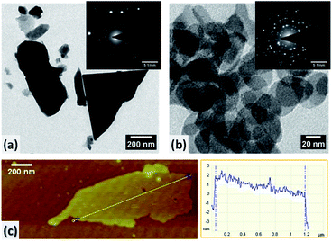 | ||
| Fig. 5 TEM images of (a) bulk Bi and (b) exfoliated BiNS 3k; respective SAED patterns shown in insets. (c) AFM image and corresponding height profile of BiNS 3k. | ||
It is well established that the edges in 2D materials (e.g. graphene, MoS2) are responsible for their electrocatalytic activity towards various reactions such as ORR12 and hydrogen evolution reaction.13 BiNS 3k with a high abundance of exposed edges represent a good model to elucidate the role of bismuthene edges towards ORR. This was evaluated in O2 saturated 0.1 M aqueous solution of KOH using linear sweep voltammetry (LSV) and the rotating ring-disk electrode (RRDE) techniques with a catalyst loading of 0.285 mg cm−2. Prior to measurements, pre-conditioning of the catalyst was performed by cycling in the working potential range for 15 cycles (Fig. S6†).
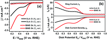
As displayed in Fig. 6a, the BiNS 3k catalyst showed a higher ORR current density of 2.39 mA cm−2 at 0.17 VRHE (potential vs. RHE) and more positive onset potential (defined as the potential at 0.01 mA cm−2) of 0.77 VRHE, compared to bulk bismuth (1.2 mA cm−2@0.17 VRHE; 0.74 VRHE@0.01 mA cm−2), indicating a higher ORR catalytic activity. Both bulk Bi and BiNS 3k showed two distinctive slopes separated by a peak around 0.48 VRHE, which are associated with two successive 2e− electrochemical reductions. The first slope at higher potential is attributed to the reduction process of O2 producing the intermediate peroxide HO2− by-product (O2 +H2O + 2e− → HO2− + OH−); whereas the second slope at lower VRHE corresponds to the reduction of HO2− to OH− (HO2− + H2O + 2e− → 3OH−).12
Furthermore, RRDE tests were conducted to clarify the 2e− ORR pathway and intermediate HO2− yield. Fig. 6b shows the total disk current density (jD) for complete O2 reduction to OH− as a function of disk potential ED, together with the HO2− generation detected by the Pt ring current (IR).11 Both IR and jD are higher for the BiNS 3k catalyst compared bulk Bi (IR: 49.11 vs. 28.84 μA at 0.2 VRHE; jD: 2.12 vs. 0.89 mA cm−2 at 0.2 VRHE).
The hydrogen peroxide yield (H2O2%) and the number of transferred electrons (n) per oxygen molecule, during the ORR, were calculated based on the following equations:12
 | (1) |
 | (2) |
Employing the above mentioned equations, it is found that the BiNS 3k catalyst yielded much less H2O2 formation (H2O2% = 62.29–59.97%), and exhibited higher n values (n = 2.75–2.80), compared to the bulk Bi (H2O2% = 86.35%∼74.02%; n = 2.27–2.52), irrespective of the applied potential, as evidenced in Fig. S7.† Overall, BiNS featured a lower H2O2% yield, onset potential, as well as higher current density and number of electrons involved in the reduction process compared to bulk Bi counterparts. These results evidently show that the enhanced edge site population of the Bi nanosheets is responsible for the improved ORR activity. Below have tried to rationalize the active role of edges in catalysing ORR compared to the basal plane.
The ORR involves, among others, the O* intermediate; we thus reasoned that the O binding energy to bismuth would have an important influence on the rate of the reaction. The Gibb's free energy corresponding to the adsorption of oxygen atom can be written as
| ΔGO* = ΔEads + 0.33 eV | (3) |
Besides, the reported literature28–32 has shown that bismuthene, due to strong spin-orbit coupling (SOC) and non-trivial bandgap (∼0.8 eV),29 is anticipated to be a 2D topological insulator, exhibiting strong conduction channels along its edges.28–30 Experimental verification of 1D topological edge states residing on edges has been demonstrated on monolayer29 and bi-layer systems.28 Theoretical investigations on a few-layer Bi predicted that 2D Bi possesses stable topological characteristics irrespective of the number of layers.33 On the other hand, for bulk Bi, which is semi-metal with very small (∼10 meV) band gap, recent experimental and theoretical work established Bi to have one-dimensional (1D) topological hinge states and be a higher-order topological insulator.31 Taking into account the above, it is thus expected that the electron rich conductive edges would provide an easier path for electron hopping between the layers of BiNS and contribute to higher ORR.
One should note that the Bi oxidation state should not be ignored: BiNS 3k exhibited lower contribution of BiOx (bulk oxidation state) than its bulk counterpart (Fig. 3a), while the functional groups, with –OH and ![[double bond, length as m-dash]](https://www.rsc.org/images/entities/char_e001.gif) O moieties, became relatively greater (Fig. 3c). Such –OH and
O moieties, became relatively greater (Fig. 3c). Such –OH and ![[double bond, length as m-dash]](https://www.rsc.org/images/entities/char_e001.gif) O moieties being surface- or edge-bound are expected to lead to the spin redistribution and charge delocalization on the neighbouring metal atoms,34 affording active centers.35
O moieties being surface- or edge-bound are expected to lead to the spin redistribution and charge delocalization on the neighbouring metal atoms,34 affording active centers.35
Conclusions
In conclusion, the mechanical exfoliation of Bi to a few-layer bismuthene has been demonstrated. Detailed spectroscopic and morphological studies verified that the exfoliation process does not introduce any foreign groups on the surface of BiNS and results in self-assembled spherules-like superstructure with diameter of ∼88 nm in diameter. Their formation, arises from convection driven evaporation dynamics of the solvent upon the drying process. Moreover, for the first time the catalytic activity for ORR of BiNS in alkaline medium is investigated. It is established that the abundance of edges in BiNS increases the ORR activity which proceeds via a 2e− reaction pathway. We suggest, that since bismuthene has been theoretically and experimentally verified to be a 2D topological insulator, it exhibits conduction channels at its edges. These 1 dimensional topological edge states would provide an easier path for electron hopping between the layers of BiNS and contribute to higher ORR performance. Based on theoretical predictions reported in the literature, we postulate that BiNS edges are more capable for adsorbing and activating O2 than the basal plane. Furthermore the possible role of Bi–OH and Bi=O functional groups on enhancing ORR has been mentioned. Our work demonstrates a simple and high-throughput approach to produce self-assembled architectures from bismuthene nanosheets and provides a pathway for employing 2D topological insulators as a new class of catalytic materials for clean energy.Experimental
Chemicals
Bulk bismuth powder (∼100 mesh, ≥99.99% trace metals basis) was purchased from Sigma-Aldrich, UK. The room temperature ionic liquid 1-butyl-3-methylimidazolium hexafluorophosphate (BMIMPF6, ≥97.0%) were purchased from Manchester Organics, UK. All analytical grade chemicals, anhydrous N,N-dimethylformamide (DMF, purity ≥99.8%), acetone (purity >99.5%) and potassium hydroxide (KOH flakes, ≥90%) were purchased from Honeywell (UK), and used without any further purification process. Pure oxygen and nitrogen gas (BOC, UK) was used for the electrochemical characterisations. Milli-Q water, with resistivity of 18.2 MΩ cm was used to prepare all aqueous solutions.Exfoliation of bismuthene nanosheets
Bismuthene nanosheets (BiNS) were exfoliated by mechanical grinding of bulk bismuth powder, using a mortar grinder system (RM200, Retsch GmbH), in an adequate quantity of BMIMPF6 ionic liquid; followed by sequential centrifugation steps, using a Thermo Scientific Sorvall ST-16 Centrifuge system.Characterizations
Prior to basic characterizations, all as-prepared powder hybrids were well-dispersed in DMF solution (≈1 mg mL−1), under ultrasonication. For morphological and elemental characterizations, well-dispersed DMF inks were drop-dried on clean Si substrates. Surface morphology was studied by using field-emission scanning electron microscope (FE-SEM, HITACHI SU5000) at an accelerating voltage of 10 kV. Energy-Dispersive X-ray analysis (EDAX), elemental mapping was performed with FE-SEM equipped package (Oxford Instruments) using Aztec software. X-ray photoelectron spectroscopy (XPS) analysis was carried out using a Kratos AXIS ultra DLD with an Al Kα (hν = 1486.6 eV) X-ray source. Elemental quantification was performed after Shirley background correction and calibration of the binding energies with respect to the C 1s line at 284.5 ± 0.2 eV associated with graphitic carbon. Raman spectroscopy was operated using an excitation wavelength of 532 nm (RL532C laser source) at a Renishaw Invia Qontor system. X-ray diffraction (XRD) analysis was conducted by employing a Bruker D8-diffractomer with Cu-Kα radiation source (40 kV, 40 mA, λ = 1.5314 Å). High resolution transmission electron microscopy (TEM) images and selected area electron diffraction (SAED) patterns were obtained on the samples, prepared by drop-drying 2 μL of DMF solution onto carbon micro-grids (Agar scientific, S147-3, holey carbon film 300 mesh Cu), and using the JEOL JEM 2011 at an accelerating voltage of 200 kV.Electrochemical characterizations and the oxygen reduction reaction (ORR) studies were performed, in O2 saturated 0.1 M aqueous solution of KOH using linear sweep voltammetry (LSV) at an Autolab, PGSTAT/FRA system. Rotating ring-disk electrode (RRDE) measurements were conducted, on a Pine Wavedriver 20 Bipotentiostat (Pine research instruments, Durham, USA), employing a typical 3-electrode configuration with a platinum wire (Pt, CHI. Instrument, Inc.) as counter electrode (CE) and Ag/AgCl (3 M KCl, CHI. Instrument, Inc.) as reference electrode (RE). For ORR activity assessment, the measured potential (VRHE) was presented with respect to reversible hydrogen electrode (RHE). The working electrode was fabricated by drop-drying the catalyst ink (DMF-based solution of bulk Bi or BiNS) onto a polished glassy carbon RRDE (Pine inst., AFE6R1PT, E6 series Pt ring, 5mm) with a desired catalyst-loading of ≈0.285 mg cm−2. Prior to measurements, pre-conditioning of the catalyst was performed by cycling in a potential range of −0.8 V to 0.2 V (versus Ag/AgCl) for 15 cycles (Fig. S6†).
Conflicts of interest
The authors have no conflicts of interest to declare.Acknowledgements
This work was supported by the Newton Bhabha Fund – Application Ref: 345713877 and by the INVEST Northern Ireland, Biodevices grant with Ref: RD0714186.Notes and references
- S. Zhang, S. Guo, Z. Chen, Y. Wang, H. Gao, J. Gómez-Herrero, P. Ares, F. Zamora, Z. Zhu and H. Zeng, Chem. Soc. Rev., 2018, 47, 982–1021 RSC.
- N. Han, Y. Wang, H. Yang, J. Deng, J. Wu, Y. Li and Y. Li, Nat. Commun., 2018, 9, 1320 CrossRef.
- D. Wu, X. Shen, J. Liu, C. Wang, Y. Liang, X.-Z. Fu and J.-L. Luo, Nanoscale, 2019, 11, 22125–22133 RSC.
- L. Li, C. Tang, B. Xia, H. Jin, Y. Zheng and S.-Z. Qiao, ACS Catal., 2019, 9, 2902–2908 CrossRef CAS.
- J. Zhou, J. Chen, M. Chen, J. Wang, X. Liu, B. Wei, Z. Wang, J. Li, L. Gu, Q. Zhang, H. Wang and L. Guo, Adv. Mater., 2019, 31, 1807874 CrossRef.
- C. Shen, T. Cheng, C. Liu, L. Huang, M. Cao, G. Song, D. Wang, B. Lu, J. Wang, C. Qin, X. Huang, P. Peng, X. Li and Y. Wu, J. Mater. Chem. A, 2020, 8, 453–460 RSC.
- R. Gusmão, Z. Sofer, D. Bouša and M. Pumera, Angew. Chem., Int. Ed., 2017, 56, 14417–14422 CrossRef.
- T. Chai, X. Li, T. Feng, P. Guo, Y. Song, Y. Chen and H. Zhang, Nanoscale, 2018, 10, 17617–17622 RSC.
- F. Yang, A. O. Elnabawy, R. Schimmenti, P. Song, J. Wang, Z. Peng, S. Yao, R. Deng, S. Song, Y. Lin, M. Mavrikakis and W. Xu, Nat. Commun., 2020, 11, 1088 CrossRef CAS.
- Z. Chen, D. Higgins, A. Yu, L. Zhang and J. Zhang, Energy Environ. Sci., 2011, 4, 3167–3192 RSC.
- S. C. Perry, D. Pangotra, L. Vieira, L.-I. Csepei, V. Sieber, L. Wang, C. Ponce de León and F. C. Walsh, Nat. Rev. Chem., 2019, 3, 442–458 CrossRef CAS.
- J. Benson, Q. Xu, P. Wang, Y. Shen, L. Sun, T. Wang, M. Li and P. Papakonstantinou, ACS Appl. Mater. Interfaces, 2014, 6, 19726–19736 CrossRef CAS.
- J. Benson, M. Li, S. Wang, P. Wang and P. Papakonstantinou, ACS Appl. Mater. Interfaces, 2015, 7, 14113–14122 CrossRef CAS.
- W. Liu, J. Benson, C. Dawson, A. Strudwick, A. P. A. Raju, Y. Han, M. Li and P. Papakonstantinou, Nanoscale, 2017, 9, 13515–13526 RSC.
- A. Ganguly, O. Trovato, S. Duraisamy, J. Benson, Y. Han, C. Satriano and P. Papakonstantinou, J. Phys. Chem. C, 2019, 123, 10646–10657 CrossRef CAS.
- E. Rabani, D. R. Reichman, P. L. Geissler and L. E. Brus, Nature, 2003, 426, 271–274 CrossRef CAS.
- B. A. Nerger, P.-T. Brun and C. M. Nelson, Sci. Adv., 2020, 6, eaaz7748 CrossRef CAS.
- H. Hu and R. G. Larson, J. Phys. Chem. B, 2006, 110, 7090–7094 CrossRef CAS.
- L. Bansal, A. Sanyal, P. Kabi, B. Pathak and S. Basu, Langmuir, 2018, 34, 8423–8442 CrossRef CAS.
- M. A. Boles, M. Engel and D. V. Talapin, Chem. Rev., 2016, 116, 11220–11289 CrossRef CAS.
- V. S. Dharmadhikari, S. R. Sainkar, S. Badrinarayan and A. Goswami, J. Electron Spectrosc. Relat. Phenom., 1982, 25, 181–189 CrossRef CAS.
- E. Haro-Poniatowski, M. Jouanne, J. F. Morhange, M. Kanehisa, R. Serna and C. N. Afonso, Phys. Rev. B: Condens. Matter Mater. Phys., 1999, 60, 10080–10085 CrossRef CAS.
- Q.-Q. Yang, R.-T. Liu, C. Huang, Y.-F. Huang, L.-F. Gao, B. Sun, Z.-P. Huang, L. Zhang, C.-X. Hu, Z.-Q. Zhang, C.-L. Sun, Q. Wang, Y.-L. Tang and H.-L. Zhang, Nanoscale, 2018, 10, 21106–21115 RSC.
- P. Hess, Nanoscale Horiz., 2020, 5, 385–399 RSC.
- S. B. Pillai, S. D. Dabhi and P. K. Jha, Int. J. Hydrogen Energy, 2018, 43, 21649–21654 CrossRef CAS.
- L. Xia, W. Fu, P. Zhuang, Y. Cao, M. O. L. Chee, P. Dong, M. Ye and J. Shen, ACS Sustainable Chem. Eng., 2020, 8, 2735–2741 CrossRef CAS.
- L. Yi, J. Chen, P. Shao, J. Huang, X. Peng, J. Li, G. Wang, C. Zhang and Z. Wen, Angew. Chem., Int. Ed., 2020, 59, 20112–20119 CrossRef CAS.
- I. Drozdov, A. Alexandradinata, S. Jeon, S. Nadj-Perge, H. Ji, R. J. Cava, B. A. Bernevig and A. Yazdani, Nat. Phys., 2014, 10, 664–669 Search PubMed.
- F. Reis, G. Li, L. Dudy, M. Bauernfeind, S. Glass, W. Hanke, R. Thomale, J. Schäfer and R. Claessen, Science, 2017, 357, 287–290 CrossRef CAS.
- P. Vishnoi, K. Pramoda and C. N. R. Rao, ChemNanoMat, 2019, 5, 1062 CrossRef CAS.
- F. Schindler, Z. Wang, M. G. Vergniory, A. M. Cook, A. Murani, S. Sengupta, A. Y. Kasumov, R. Deblock, S. Jeon, I. Drozdov, H. Bouchiat, S. Guéron, A. Yazdani, B. A. Bernevig and T. Neupert, Nat. Phys., 2018, 14, 918–924 Search PubMed.
- A. K. Nayak, J. Reiner, R. Queiroz, H. Fu, C. Shekhar, B. Yan, C. Felser, N. Avraham and H. Beidenkopf, Sci. Adv., 2019, 5, eaax6996 Search PubMed.
- Z. Liu, C.-X. Liu, Y.-S. Wu, W.-H. Duan, F. Liu and J. Wu, Phys. Rev. Lett., 2011, 107, 136805 CrossRef.
- Q. Yang, Z. Xiao, D. Kong, T. Zhang, X. Duan, S. Zhou, Y. Niu, Y. Shen, H. Sun, W. Shaobin and Z. Linjie, Nano Energy, 2019, 66, 104096 CrossRef CAS.
- X. Qi, W. Song and J. Shi, PLoS One, 2017, 12, e0173864 CrossRef.
Footnotes |
| † Electronic supplementary information (ESI) available: Statistical analysis of FESEM, XPS and Raman spectroscopic data, and supporting figures of morphological, XPS, Raman, XRD and ORR study. See DOI: 10.1039/d0ra09763b |
| ‡ First 2 authors have contributed equally. |
| This journal is © The Royal Society of Chemistry 2020 |

