 Open Access Article
Creative Commons Attribution 3.0 Unported Licence
Shear-structured MoNb6O18 as a new anode for lithium-ion batteries†
Jialin
Cheng
,
Fengqi
Lu
 * and
Xiaojun
Kuang

Key Laboratory of New Processing Technology for Nonferrous Metal & Materials, Ministry of Education Guangxi Key Laboratory of Optical and Electronic Materials and Devices, College of Materials Science and Engineering, Guilin University of Technology, Guilin 541004, P. R. China. E-mail: lufengqi@glut.edu.cn
First published on 3rd September 2021
Abstract
Owing to their high theoretical capacities, safe operational voltage, unique tunnel-shaped structural features for fast lithium ion transfer, and structural stability, niobium-based oxides are regarded as promising candidate anode materials for lithium-ion batteries (LIBs). Here, molybdenum niobium oxide (MoNb6O18) with a high theoretical capacity of 399 mA h g−1 (Mo6+/Mo4+ and Nb5+/Nb3+) was developed as a new anode material for LIBs. The crystal structure of MoNb6O18 was observed to display a Wadsley–Roth phase of the ReO3 shear structure. The discharge capacity of micron-sized particles of MoNb6O18 was measured to be 219.4 mA h g−1 with a high initial Coulombic efficiency of 96.8% at 0.2C and 154.3 mA h g−1 at 1C from 1.0 to 3.0 V. The results of ex situ X-ray diffraction (XRD) experiments revealed the ability of MoNb6O18 to serve as an intercalation-type anode material for lithium ion storage with outstanding structural stability. Also, an LiMn2O4//MoNb6O18 full cell displayed desirable lithium-ion storage properties.
Introduction
Lithium-ion batteries (LIBS), as the most popular energy storage device, are widely used in various fields such as mobile electronics products, grid storage, and even in electric vehicles (EVs).1–6 Graphite, as the prevailing anode for commercial LIBs, has a high theoretical capacity (372 mA h g−1). However, its use could result in lithium plating or the formation of lithium dendrites when working at high charging/discharging rates and at low potentials, and thus has safety concerns.7–10 It has been found that TiO2,11 Li4Ti5O12,12 LiCrTiO413 and other titanium-based materials are suitable for use as anode materials for LIBs with a safe voltage of about 1.55 V. Unfortunately, their disadvantages of low theoretical capacity and low energy density significantly hinder their practical applications in next-generation LIBs requiring high power density levels and long lifespans.14–16 Therefore, it is urgent to investigate suitable anode materials with safe working potentials and high energy density and cycling stability levels, especially for EVs.17Recently, niobium-based oxides have been extensively investigated as high-rate anode materials for LIBs, due to their high theoretical capacities based on multielectron reactions, fast lithium ion transport, and, most importantly, safe operating voltage (at just above 1.0 V vs. Li+/Li).18–20 Therefore, niobium-based oxide anodes are promising candidates for high-power LIB anodes, specifically in EVs.21 Most niobium-based oxides form the Wadsley–Roth crystallographic shear structure with blocks consisting of distorted MO6 octahedra sharing corners, and are built of n × m × ∞ ReO3-type units (with n and m denoting the numbers of MO6 octahedra along the length and width of the blocks).22 This unique open-tunnel structure can promote lithium ion diffusion and enhance lithium storage capacities.19 Recently, Wadsley–Roth-shear-structured niobium-based oxides, including W5Nb16O55,23 MoNb12O33,24 WNb12O33,25 Mo3Nb14O44,26 W3Nb14O44,27 TiNb2O7,28 Ti2Nb10O29,29 have been investigated as high-rate anode materials for LIBs. Mo–Nb–O oxides with Wadsley–Roth shear structure anode materials have shown great potential for high-rate lithium ion storage. To the best of our knowledge, MoNb12O33, Mo3Nb14O44 and Mo3Nb2O14 are the only three available Mo–Nb-based oxide anode materials. Very few Mo–Nb–O oxides have so far been used as anodes. In the work described here, a new micro-sized Mo–Nb–O oxide (MoNb6O18) particle, one made by tailoring the ratio of Mo to Nb, was investigated as an anode material for LIBs.
Results and discussion
The crystal structure of MoNb6O18 was characterized using X-ray diffraction (XRD). As shown in Fig. 1, sharp diffraction peaks were observed, indicating its good crystallinity. To the best of our knowledge, no crystal structure of MoNb6O18 has been previously reported; and no information about its crystal structure was found in the Inorganic Crystal Structure Database (ICSD) and the International Centre for Diffraction Data (ICDD). Careful analysis of the XRD pattern of MoNb6O18 showed its diffraction characteristics to be very similar to those of MoTa12O33. According to this result, MoNb6O18 formed a crystal structure similar to that of MoTa12O33, i.e., a monoclinic Wadsley–Roth shear structure in an I2/m space group. An XRD Rietveld refinement was performed using the Wadsley–Roth shear structure of MoTa12O33 as the initial structural model; the refinement converged to an Rwp of 10.35%, Rp of 7.48%, and RBragg of 3.32%. The cell lattice parameters of MoNb6O18 were determined to be a = 17.730(2) Å, b = 3.822(7) Å, c = 19.417(2) Å, β = 106.43(6)°, with a unit-cell volume V of 1260.46(2) Å3. This result confirmed that the as-prepared MoNb6O18 adopted the Wadsley–Roth shear structure with many Nb and O vacancies. As shown in the inset of Fig. 1, 3 × 4 NbO6 octahedral blocks were spread to an indefinite extent on the a–c layer, and extended indefinitely along the direction of the b-axis. The 3 × 4 blocks linked to each other as a result of edge-sharing NbO6 octahedra, and corner-sharing MoO4 tetrahedra. The NbO6 octahedra shared corners with each other within the block, thus providing many vacant sites for lithium ion storage and fast diffusion.24 The Mo![[thin space (1/6-em)]](https://www.rsc.org/images/entities/char_2009.gif) :
:![[thin space (1/6-em)]](https://www.rsc.org/images/entities/char_2009.gif) Nb atomic ratio was determined from an ICP analysis to be 0.95
Nb atomic ratio was determined from an ICP analysis to be 0.95![[thin space (1/6-em)]](https://www.rsc.org/images/entities/char_2009.gif) :
:![[thin space (1/6-em)]](https://www.rsc.org/images/entities/char_2009.gif) 6, consistent with the theoretical value (1
6, consistent with the theoretical value (1![[thin space (1/6-em)]](https://www.rsc.org/images/entities/char_2009.gif) :
:![[thin space (1/6-em)]](https://www.rsc.org/images/entities/char_2009.gif) 6) in MoNb6O18 oxide.
6) in MoNb6O18 oxide.
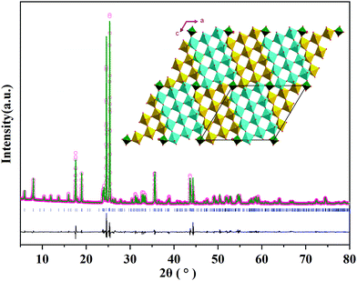 | ||
| Fig. 1 XRD pattern of MoNb6O18 and the corresponding Rietveld refinement result, with the inset image displaying a view of the crystal structure along the b axis. | ||
The morphology and microstructure of MoNb6O18 samples were observed using scanning electron microscopy (SEM) and transmission electron microscopy (TEM). In the SEM image (Fig. 2a), MoNb6O18 exhibited irregular rod-like particles with a size distribution ranging from 0.3 to 3 μm. The elements Mo, Nb and O were determined to be uniformly distributed in each MoNb6O18 rod-like particle (Fig. 2b–d). The observed bright diffraction spot in the selected-area electron diffraction (SAED) pattern of an MoNb6O18 sample, shown in Fig. 2e, can be well indexed to (110), (![[1 with combining macron]](https://www.rsc.org/images/entities/char_0031_0304.gif) 05) and (015) planes of Wadsley–Roth shear structure characteristic of MoNb6O18. The inter-planar distances observed in a high-resolution TEM (HRTEM) image of MoNb6O18, shown in Fig. 2f, were measured to be about 0.390 and 0.379 nm, corresponding to the (
05) and (015) planes of Wadsley–Roth shear structure characteristic of MoNb6O18. The inter-planar distances observed in a high-resolution TEM (HRTEM) image of MoNb6O18, shown in Fig. 2f, were measured to be about 0.390 and 0.379 nm, corresponding to the (![[1 with combining macron]](https://www.rsc.org/images/entities/char_0031_0304.gif) 05) and (110) planes, respectively.
05) and (110) planes, respectively.
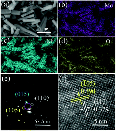 | ||
| Fig. 2 Morphology and microstructure of MoNb6O18. (a) SEM image. (b–d) EDS elemental mapping images for (b) Mo, (c) Nb, and (d) O. (e) SAED pattern. (f) HRTEM image. | ||
The lithium-ion storage properties of MoNb6O18 electrodes were investigated by taking CV and GCD measurements of them at room temperature. Fig. 3a shows CV curves of MoNb6O18 acquired in different voltage ranges (specifically 0.8–3.0 V, 1.0–3.0 V and 1.2–3.0 V) at a scanning rate of 0.2 mV s−1. During the anodic scanning process, reduction peaks were observed at about 2.28 V (R1) and 1.92 V (R2), and could be attributed to conversions of Mo(IV) to Mo(V), and of Mo(V) to Mo(IV).26 Peaks were also observed at about 1.72 V, and could be ascribed to the reduction of Nb(V) to Nb(IV).30–32 In addition, peaks were observed at about 1.14 V (R4), and corresponded to the reduction of Nb(IV) to Nb(III) at the voltage ranges 0.8–3.0 V and 1.0–3.0 V. During the cathodic scanning process, one broad oxidation peak appeared at about 1.88 V. Comparison of CV curves obtained using the three different voltage ranges clearly showed the MoNb6O18 electrode displaying the highest peak current for the voltage range 1.0–3.0 V.
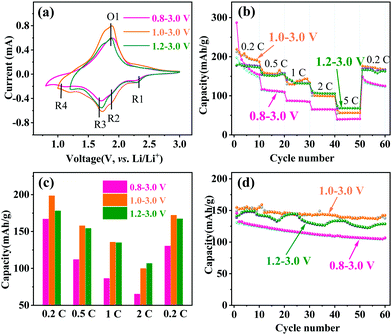 | ||
| Fig. 3 Electrochemical performances of MoNb6O18. (a) CV curves at 0.2 mV s−1, (b) rate capabilities, (c) histogram of rate capabilities, and (d) cycling property at 1C. | ||
The rate capability and cycling performance of MoNb6O18 were tested at various rates and voltage ranges. Fig. 3b illustrates the rate properties from 0.2 to 5C. In the first cycle at 0.2C, the MoNb6O18 electrode showed the highest discharge capacity of 287.3 mA h g−1 at the voltage range 0.8 to 3.0 V, but a rather low charge capacity of 197.7 mA h g−1, which could be ascribed to the irreversible reaction leading to capacity loss. In contrast, the electrode exhibited a discharge/charge capacity of 219.3/212.4 mA h g−1 with an initial Coulombic efficiency as high as 96.8% from 1.0 to 3.0 V. The average charge capacities are displayed in Fig. 3c; the MoNb6O18 electrode exhibited the highest average charge capacity of 198.2 mA h g−1 at 0.2C from 1.0 to 3.0 V. However, at a high current density of 5C, it showed the highest average charge at the voltage range 1.2 to 3.0 V, which could be attributed to a more reversible reaction. When the current density returned to 0.2C, the specific capacities almost recovered to their original values for the voltage ranges 1.0 to 3.0 V and 1.2 to 3.0 V, in contrast with a low specific capacity for the range 0.8 to 3.0 V. Determining the cycling stability of the electrode materials is an important way to assess LIBs. Fig. S1 (ESI†) shows the first-cycle voltage profiles at 1C. Three voltage ranges (0.8–3.0, 1.0–3.0 and 1.2–3.0 V) gave first discharge capacities of 145.8, 155.0 and 145.9 mA h g−1, respectively. Cycling performances of an MoNb6O18 electrode at 1C were determined at various voltage ranges, as shown in Fig. 3d. The cycle profile fluctuated to a certain extent, and this fluctuation could be attributed to the environmental differences between daytime and nighttime during the winter, when these experiments were performed. Compared with the other two voltage ranges, the electrode exhibited the highest charge capacity of 137.6 mA h g−1 and retention rate of 93% after 60 cycles between 1.0 and 3.0 V. The lithium-storage properties of MoNb6O18 electrode were also compared with those of reported Nb-based and other anodes (Table S1, ESI†).5,20,24,33,34
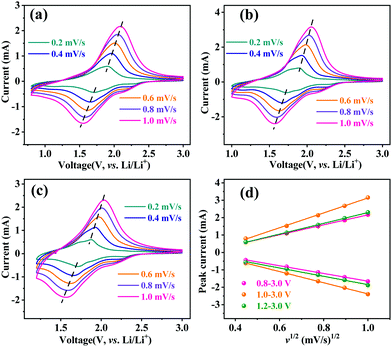
The Li-ion diffusion behavior of the MoNb6O18 electrode was investigated by taking CV measurements of this electrode at the different voltage ranges at various scan speeds from 0.2 to 1.0 mV s−1. As shown in Fig. 4, when the scan rate was increased from 0.2 to 1.0 mV s−1, the reduction and oxidation peaks shifted to lower and higher voltages, respectively. Based on the linear relationship between the scan rate and peak current (Fig. 4d), the Li-ion diffusion coefficient of the MoNb6O18 electrode was determined by using the Randles–Sevcik equation (eqn (1)).35
| Ip = 2.69 × 10⁵ × n1.5C0SDCV0.5v0.5 | (1) |
The apparent lithium-ion diffusion properties of the MoNb6O18 electrode were further investigated by performing the galvanostatic intermittent titration technique (GITT) during the whole cycle at different voltages (Fig. 5). A current density of 0.1C was applied for 30 minutes to the electrode to control the Li-ion insertion and extraction, following by a relaxation process lasting for 120 minutes. The apparent Li-ion diffusion coefficient (DGITT) values were calculated using the equation35
| DGITT = (4/πτ)(mBVm/MBS)2(ΔEs/ΔEτ)2 (τ ≤ l2/D), | (2) |
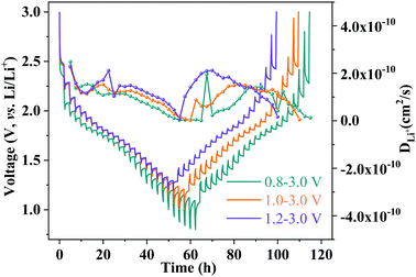 | ||
| Fig. 5 GITT curves and Li-ion diffusion coefficient profiles of an MoNb6O18 electrode at 0.1C with different voltage windows. | ||
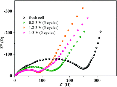
Electrochemical impedance spectra (EIS) of the MoNb6O18 electrode were acquired with a fresh cell and after 5 cycles at various voltage ranges at 0.2C (Fig. 6). Each Nyquist EIS plot was found to contain a semicircle at the high- to middle-frequency region and a sloping line at the low-frequency region—with the former relevant to the charge-transfer impedance on the electrode–electrolyte interface (Rct), and the latter assigned to the semi-infinite diffusion of lithium ions in the electrode.38 Interestingly, the diameters of the semicircles at the high to middle frequencies decreased obviously after 5 cycles, revealing an enhancement of the charge-transfer efficiency after cycling. This phenomenon could be attributed to the irreversible insertion of lithium ions into the MoNb6O18 electrode leading to improvement in the electronic conductivity of the electrode.39,40 The values of the diameters of the semicircle in the voltage ranges 1–3 V and 1.2–3 V were seen to be almost equal and smaller than that of the voltage range 0.8–3 V, indicating that the insertion of lithium ions into the MoNb6O18 electrode occurred most easily in the voltage ranges 1.0–3.0 V and 1.2–3 V.
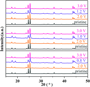
The structural evolution of MoNb6O18 during charging/discharging at 0.1C was further clarified from the results of an ex situ XRD experiment. As shown in Fig. 7, after a full cycle of insertion and extraction of lithium ions, all diffraction peaks almost returned to their original peak positions and recovered their peak intensities, indicating the high reversibility of the lithium ion insertion into/extraction from the structure MoNb6O18. This result verified that MoNb6O18 is an intercalation-type anode material for lithium-ion storage and has outstanding structural stability.
To estimate the potential application of MNO in LIBs, a full battery cell was fabricated with MoNb6O18 as the anode and LiMn2O4 as the cathode (LMO//MNO).10,41,42 The working voltage of this LMO//MNO full cell was about 2.0 V (Fig. S2b, ESI†). As shown in Fig. 8, the initial respective charge and discharge capacities of the full cell were 226.2 and 196.3 mA h g−1 with a Coulombic efficiency of 86.8% at 0.2C. From the fifth cycle onward, the Coulombic efficiency was above 98%, indicating a highly reversible charge/discharge process. After 30 cycles, the full cell maintained a discharge capacity of 152 mA h g−1. The properties of the full cell were comparable to those of an LiMn2O4//porous MoNb12O33 microsphere full cell (∼170 mA h g−1 at 1C after 100 cycles)24 and LiMn2O4//nanowire Mo3Nb14O44 full cell (201 mA h g−1 at 0.1C, 73 mA h g−1 at 5C after 500 cycles).33 A red-LED (Fig. 8 inset) was successfully powered by the LMO//MNO full cell after 30 cycles, certifying the potential practicability of the full cell. The excellent results for this full cell revealed that MoNb6O18 has potential applications in LIBs.
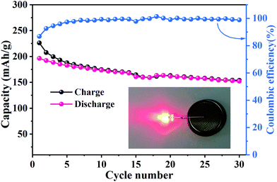 | ||
| Fig. 8 Cycling properties and Coulombic efficiency levels of an LMO//MNO full cell at 0.2C; inset: red-LED powered by the LMO//MNO full cell after 30 cycles. | ||
Conclusions
In summary, MoNb6O18 was investigated as a new intercalation-type anode material for LIBs. Pure-phase micro-scale MoNb6O18 was fabricated using a simple solid-state method with MoO3 and Nb2O5 as raw materials. MoNb6O18 formed a monoclinic shear ReO3-type crystal structure in the space group I2/m, consisting of a (3 × 4)∞ NbO6 octahedron block and an MoO4 tetrahedron at the corner of the block. In the half-cells, the MoNb6O18 electrode operated at a safe voltage (of about 1.72 V) and showed a reversible capacity of up to 219.4 mA h g−1 at 0.2C and 154.3 mA h g−1 at 1C in the voltage range 1.0 V to 3.0 V. Moreover, the LiMn2O4//MoNb6O18 full cell delivered charge and discharge capacities of 226.2 and 196.3 mA h g−1 at 0.2C with an energy density of 393 W h kg−1. Due to its multi-electron reactions, safe operating voltage, and reversible crystal structural evolution, MoNb6O18 is expected—in particular after subjecting it to morphology optimization, nano-sizing and carbon synergy—to be a competitive candidate anode material for large-scale energy storage systems, especially in EVs. Also, this work has provided some new insights for investigations of M–Nb–O mix-oxides used as anode materials for LIBs.Conflicts of interest
The authors declare no conflict of interest.Acknowledgements
This work was financially supported by the Guangxi Natural Science Foundation (No. 2020GXNSFAA159005).References
- R. Schmuch, R. Wagner, G. Hörpel, T. Placke and M. Winter, Nat. Energy, 2018, 3, 267–278 CrossRef CAS.
- X. Hu, S. E. Li and Y. Yang, IEEE Trans. Transp. Electrif., 2017, 2, 140–149 Search PubMed.
- B. Alex, W. Lars, T. Andrea and T. Axel, J. Cleaner Prod., 2018, 89, 292–308 Search PubMed.
- S. J. Kim, H. C. Park, M. C. Kim, D. M. Kim, Y. W. Lee and K. W. Park, J. Power Sources, 2015, 273, 707–715 CrossRef CAS.
- C. Wei, H. Fei, Y. Tian, Y. An, Y. Tao, Y. Li and J. Feng, Chin. Chem. Lett., 2020, 31, 980–983 CrossRef CAS.
- Z. Luo, C. Liu and S. Fan, J. Mater. Chem. A, 2019, 7, 3642–3647 RSC.
- M. Armand and J. M. Tarascon, Nature, 2008, 451, 652–657 CrossRef CAS PubMed.
- R. Srinivasan and L. Srinivasan, J. Power Sources, 2015, 293, 876–882 CrossRef CAS.
- J. B. Goodenough and Y. Kim, J. Power Sources, 2011, 196, 6688–6694 CrossRef CAS.
- Z. Zhang, Y. Huang, X. Li, S. Zhang, Q. Jia and T. Li, Chem. Eng. J., 2021, 421, 129827 CrossRef CAS.
- S. I. Choi, E. J. Jung, M. Park, H. S. Shin and S. W. Yong, Appl. Surf. Sci., 2020, 508, 145237 CrossRef CAS.
- T. Yi, S. Yang and X. J. Ying, J. Mater. Chem. A, 2015, 3, 5750–5777 RSC.
- G. Hao, L. Ning, D. Li, C. Dai and D. Wang, J. Phys. Chem. C, 2009, 113, 6324–6326 CrossRef.
- S. Lee, W. Eom, H. Park and T. H. Han, ACS Appl. Mater. Interfaces, 2017, 9, 25332–25338 CrossRef CAS PubMed.
- K. Kanamura, T. Umegaki, H. Naito, Z. Takehara and T. Yao, J. Appl. Electrochem., 2001, 31, 73–78 CrossRef CAS.
- D. Yoshikawa, Y. Kadoma, J. M. Kim, K. Ui, N. Kumagai, N. Kitamura and Y. Idemoto, Electrochim. Acta, 2010, 55, 1872–1879 CrossRef CAS.
- T. Tomohiro, Y. Shinpei, F. Yuki, A. Kengo, U. Kotaro, I. Ryoji and S. Yoji, J. Electrochem. Soc., 2018, 165, A1231–A1237 CrossRef.
- Q. Fu, X. Zhu, R. Li, G. Liang, L. Luo, Y. Chen, Y. Ding, C. Lin, K. Wang and X. Zhao, Energy Environ. Mater., 2020, 30, 401–411 Search PubMed.
- Y. Yang and J. Zhao, Adv. Sci., 2021, 2004855 CrossRef PubMed.
- L. Qin, Y. Liu, S. Xu, S. Wang, X. Sun, S. Zhu, L. Hou and C. Yuan, Small Methods, 2020, 4, 2000630 CrossRef CAS.
- Q. Deng, Y. Fu, C. Zhu and Y. Yu, Small, 2019, 15, 1804884 CrossRef PubMed.
- R. S. Roth and A. D. Wadsley, Acta Crystallogr., 1965, 19, 26–32 CrossRef CAS.
- K. J. Griffith, K. M. Wiaderek, G. Cibin, L. E. Marbella and C. P. Grey, Nature, 2018, 559, 556–563 CrossRef CAS PubMed.
- X. Zhu, J. Xu, Y. Luo, Q. Fu, G. Liang, L. Luo, Y. Chen, C. Lin and X. S. Zhao, J. Mater. Chem. A, 2019, 7, 6522–6532 RSC.
- A. D. Saritha, B. V. Pralong, A. U. V. Varadaraju and B. B. Raveau, J. Solid State Chem., 2010, 183, 988–993 CrossRef.
- X. Ma, P. Chen, M. Qian, D. Wu, J. Du, X. Chen, R. Dai, M. Sha, Z. Zi and J. Dai, J. Alloys Compd., 2021, 864, 158379 CrossRef CAS.
- Y. Yang, H. Zhu, J. Xiao, H. Geng, Y. Zhang, J. Zhao, G. Li, X. Wang, C. Li and Q. Liu, Adv. Mater., 2020, 32, 1905295 CrossRef CAS PubMed.
- K. J. Griffith, I. D. Seymour, M. A. Hope, M. M. Butala, L. K. Lamontagne, M. B. Preefer, C. P. Koçer, G. Henkelman, A. J. Morris, M. J. Cliffe, S. E. Dutton and C. P. Grey, J. Am. Chem. Soc., 2019, 141, 16706–16725 CrossRef CAS PubMed.
- S. Deng, Y. Zhang, D. Xie, L. Yang, G. Wang, X. Zheng, J. Zhu, X. Wang, Y. Yu, G. Pan, X. Xia and J. Tu, Nano Energy, 2019, 58, 355–364 CrossRef CAS.
- X. Ma, L. Cheng, L. Li, X. Cao, Y. Ye, Y. Wei, Y. Wu, M. Sha, Z. Zi and J. Dai, Electrochim. Acta, 2020, 332, 135380 CrossRef CAS.
- C. Yang, S. Yu, C. Lin, F. Lv, S. Wu, Y. Yang, W. Wang, Z. Zhu, J. Li, N. Wang and S. Guo, ACS Nano, 2017, 11, 4217–4224 CrossRef CAS PubMed.
- U. K. Sen, A. Shaligram and S. Mitra, ACS Appl. Mater. Interfaces, 2014, 6, 14311–14319 CrossRef PubMed.
- R. Li, G. Liang, X. Zhu, Q. Fu, Y. Chen, L. Luo and C. Lin, Energy Environ. Mater., 2021, 4, 65–71 CrossRef CAS.
- X. Yang, Y. Wang, B. Hou, H. Liang, X. Zhao, H. Fan, G. Wang and X. Wu, Acta Metall. Sin. (Engl. Lett.), 2021, 24, 390–400 CrossRef.
- A. J. Bard and L. R. Faulkner, Russ. J. Electrochem., 2002, 38, 1364–1365 CrossRef.
- Z. Zhou, S. Lou, X. Cheng, B. Cui and G. Yin, ChemistrySelect, 2020, 5, 1209–1213 CrossRef CAS.
- Q. Tian, W. Ye, H. Yu, X. Cheng, H. Zhu, N. Long, M. Shui and J. Shu, Ceram. Int., 2019, 45, 1893–1899 CrossRef CAS.
- F. Lu, Q. Chen, S. Geng, M. Allix, H. Wu, Q. Huang and X. Kuang, J. Mater. Chem. A, 2018, 6, 24232–24244 RSC.
- R. Song, H. Song, J. Zhou, X. Chen, B. Wu and H. Y. Yang, J. Mater. Chem., 2012, 22, 12369–12374 RSC.
- H. Chen, L. X. Ding, K. Xiao, S. Dai, S. Wang and H. Wang, J. Mater. Chem. A, 2016, 4, 16318–16323 RSC.
- Y. Wang, B. Hou, J. Guo, Q. Ning, W. Pang, J. Wang, C. Lv and X. Wu, Adv. Energy Mater., 2018, 8, 1703252 CrossRef.
- B. Hou, Y. Wang, J. Guo, Y. Zhang, Q. Ning, Y. Yang, W. Li, J. Zhang, X. Wang and X. Wu, ACS Appl. Mater. Interfaces, 2018, 10, 3581–3589 CrossRef CAS PubMed.
Footnote |
| † Electronic supplementary information (ESI) available. See DOI: 10.1039/d1ma00590a |
| This journal is © The Royal Society of Chemistry 2021 |

