The hole transporting behaviour of Cu2AgInS4 and Cu2AgInSe4 for a carbon electrode-based perovskite solar cell†
Pratheep
Panneerselvam
 and
Subramania
Angaiah
 *
*
Electro-Materials Research Laboratory, Centre for Nanoscience and Technology, Pondicherry University, Puducherry-605 014, India. E-mail: a.subramania@gmail.com
First published on 19th November 2020
Abstract
In this work, quaternary Cu2AgInS4 (CAIS) and Cu2AgInSe4 (CAISe) nanoparticles (NPs) were synthesised by a simple hot injection method and were confirmed by XRD and Raman spectroscopy analysis. The morphologies of the synthesised CAIS and CAISe nanoparticles were confirmed by HR-TEM. The synthesised CAIS and CAISe NPs were deposited over pearl carbon (C) coated FTO and this was confirmed by Raman spectroscopy analysis. The photoluminescence (PL) spectra of the perovskite deposited onto CAIS NPs@C and CAISe NPs@C films were recorded to determine their charge extracting behaviour. The PL intensity was quenched on the CAIS NPs@C film and this is consistent with its photovoltaic performance. Among these two hole transporting material, the distribution of CAIS NPs onto a pearl carbon based counter electrode (CE) enhanced the charge transport and charge collection efficiency and reduced the recombination loss more than the CAISe NPs deposited onto a pearl carbon based CE. The synergistic effect of pearl carbon and CAIS NPs reduced the leakage current and increased the charge transport at the pearl carbon/perovskite interface. This enhanced the device performance, which exhibited a maximum PCE of 4.24% with ∼57% improvement over the pearl carbon CE.
1. Introduction
In the present solar cell research, perovskite solar cells (PSCs) have attracted the attention of researchers due to their high-power conversion efficiency (PCE). The PCE has increased in accordance with the timeline, and the maximum obtained PCE for PSCs has risen from 3.8 to 25% over a decade.1,2 The trend in the PCE of PSCs is somewhat higher than that of second-generation solar cells such as CIGS thin-film solar cells.3 The PSC was assembled by a transparent conducting metal oxide electrode and an electron transport layer (ETL) with a perovskite light absorbing layer, followed by a hole transport layer (HTL) capped with a noble metal counter electrode.2,4–6 Even though the PCE of a PSC is higher than that of a second-generation solar cell, its total processing cost is higher than that of second and first-generation solar cells due to the usage of a noble metal counter electrode. Metal CEs consist of a large portion of over 70% of the fabrication cost. In a PSC, the CEs made by Au or Ag are mostly coated by an evaporation technique. In the case of a Au CE, 40% of material utilization in the evaporator would cost around ∼$175 per m2. This will influence the overall fabrication cost.7,8A Ag-based CE is cheaper than a Au-based CE and exhibits a comparable PCE, but the diffusion or reaction of this metal electrode with the perovskite layer is one of the origins of device instability.7,9 In order to decrease the manufacturing costs, it is important to replace the evaporated noble metal electrode with relatively low-cost and chemically stable materials. Therefore, in recent years, researchers around the world have endeavoured to develop a low-cost carbon-based CE, which has special characteristics such as having cheap materials, and is printable, flexible and stable against corrosive chemicals.10,11 Until now, PSCs based on a carbon CE have been slower than traditional solar cells, hence researchers have paid much more attention to improving the PSC device performance towards its intensive commercialization use.
The device performance significantly depends on charge transport at the carbon and perovskite interface. In carbon-based PSCs, usually carbon black or a mixture of carbon black with graphite is used as a CE. It has been reported that spherical carbon black with added graphite flakes has more gaps and pores in the CE and hence, at the interface between the carbon and the perovskite, the charge transport is affected.12 Improving the contact of the perovskite/carbon interface is necessary for device performance. Many strategies have been developed to facilitate charge transport at the carbon and perovskite interface to improve the performance of PSCs. In recent years, carbon-based PSCs with inorganic hole transport materials (HTMs) have attracted much attention. Inserting a low-cost inorganic HTL layer between the perovskite and carbon electrode or incorporating the HTM into the carbon has been carried out to improve the charge transport at the interface of the carbon/perovskite. In this way, recently, ternary quantum dots (QDs) of CuInS2 have been used as a HTL in PSCs, and have exhibited improved stability due to their hydrophobic nature.13
Qiliang Wu et al. introduced quaternary Cu2ZnSnS4 (CZTS) as an alternative hole transport material for a PSC, in order to improve the device performance and achieved a PCE of 12.75% with an improved Jsc value compared to a spiro-MeOTAD-based PSC.18 In general, quaternary P-type semiconducting materials are highly chemically stable, have high charge mobility and also their band position matches well with the perovskite materials. Shuai Ma et al. reported that the colloidal semiconductor Cu2ZnSn(S1−xSex)4 has high conductivity and a good electrocatalytic nature. The study was carried out with a dye/quantum dot-sensitized solar cell based on the colloidal semiconductor Cu2ZnSn(S1−x,Sex)4 as a CE, achieving an enhanced PCE compared to with a Pt CE.15 In addition to this report, a number of research groups have also demonstrated that quaternary semiconducting nanoparticles are more suitable for carbon-based PSCs.
Recently, Khattak et al. reported device modelling of kesterite and other quaternary materials such as HTLs for MASnI3-based perovskite solar cells. A kesterite HTL for a MASnI3-based perovskite solar cell showed an improved PCE of 19.52%, with a short-circuit current of 29.45 mA cm−2, an open circuit voltage of 0.86 V and a fill factor of 76.74%. The Shockley–Queisser (S–Q) limit for MASnI3-based perovskite solar cells is around 25%.16 To date, the most efficient MASnI3-based PSC exhibited 7.13% PCE with good reproducibility.17 Kesterite Cu-based quaternary semiconductor HTLs are important because Cu is an earth-abundant element, is highly conductive, very stable and solution-processable.18 These HTLs have an important role in the improvement of PCEs by reducing carrier recombination at back contact by introducing a strong back surface field.16 Furthermore, it has been reported that the valence band maximum (VBM) for MASnI3 is −5.47 eV and it is −5.37 eV for a Cu-based quaternary semiconductor, and these results match well with those of perovskite materials.13,18–21 Therefore, this will increase the charge extraction and charge transport at the perovskite/CAIS NPs@pearl carbon layer.
Herein, we prepared quaternary colloidal CAIS NPs and CAISe NPs by a hot injection method. They were coated over pearl carbon to form a low temperature carbon-based CE for PSCs. The impact of these NPs over the pearl carbon CE on the charge transporting nature and the photovoltaic performance of the PSC is studied. Due to the high hole mobility of quaternary colloidal NPs, the PSC based on the CAIS NPs@pearl carbon CE showed better carrier extraction for transfer from the perovskite layer. The device exhibited a maximum PCE of 4.24% with ∼57% improvement over that of the device based on bare pearl carbon CE.
2. Experimental section
2.1 Materials
The following materials were used to prepare colloidal quaternary NPs of Cu2AgInSe4 and Cu2AgInS4, a TiO2 thin film and MASnI3 perovskite materials: selenium powder (Sigma-Aldrich), copper(II) chloride (Sigma-Aldrich), indium(III) chloride (Sigma-Aldrich), L-cysteine, oleylamine (Sigma-Aldrich), 1-dodecanethiol (DDTh) (Sigma-Aldrich), silver chloride (Sigma-Aldrich), ethanol, methanol, chloroform, titanium(IV) isopropoxide (Sigma-Aldrich), polyvinylpyrrolidone (Aldrich), acetic acid (Merck), SnI2 (Alfa Aesar), CH3NH3I (TCI), dimethylformamide (SRL), acetylacetone (Merck) and a fluorine-doped tin oxide glass plate.2.2 Synthesis of Cu2AgInSe4 and Cu2AgInS4 NPs
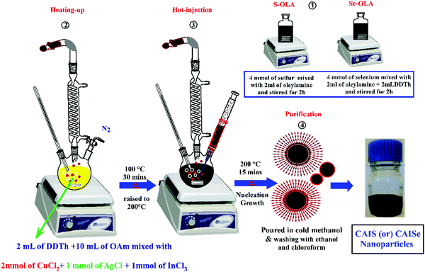
The Cu2AgInSe4 and Cu2AgInS4 NPs were prepared by the hot injection method described in our previous report.22,23 According to the method, 2 mmol of CuCl2, 1 mmol of AgCl, 1 mmol of InCl3, 2 mL of DDTh, and 10 mL of OAm were loaded into a 100 mL three-neck flask. This mixture was refluxed at 100 °C under an inert atmosphere for 30 min and then the temperature was gradually increased to 200 °C. At this temperature, the pre-prepared selenium solution (obtained by dissolving 4 mmol of Se metal powder in a mixture of 2 mL of OAm) was quickly injected into the mixture and the reaction temperature was maintained for 10 min. This method helps the nucleation and growth process. After 15 min, the reaction was stopped and cold methanol was added to obtain the CAISe NPs. The nanoparticles were washed with ethanol and methanol, and then dispersed in chloroform. Using the same method, CAIS NPs were synthesised using a sulfur solution (obtained by dissolving 4 mmol sulfur powder in 2 mL of OAm) (Fig. 1).2.3 Fabrication of PSC
Perovskite solar cells were fabricated according to the following procedure. Briefly, a TiO2 thin film was deposited by an artist spray gun assisted pyrolysis method. A perovskite MASnI3 precursor solution was prepared by dissolving 40 wt% of SnI2 and CH3NH3I at a molar ratio of 1![[thin space (1/6-em)]](https://www.rsc.org/images/entities/char_2009.gif) :
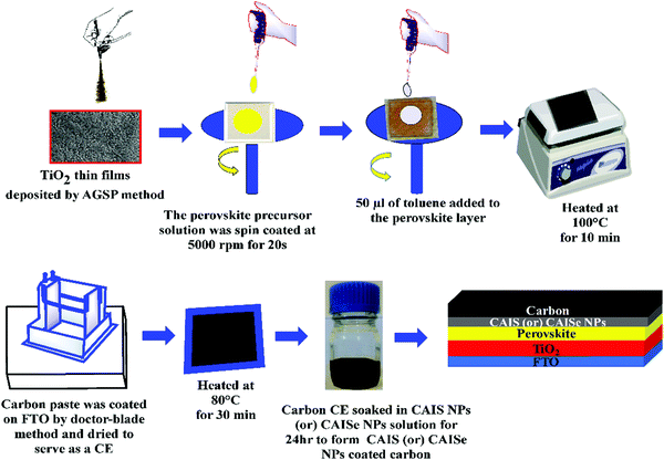
:![[thin space (1/6-em)]](https://www.rsc.org/images/entities/char_2009.gif) 1 in anhydrous DMF. This precursor solution was spin coated over the TiO2 thin film at 5000 rpm for 20 s. A small amount of 50 μL of toluene was added to the perovskite layer and it was then heated at 100 °C.24 Furthermore, 2 g pearl carbon was mixed in 5 mL chlorobenzene and stirred well for 12 h to form a carbon paste. This carbon paste was coated by the doctor-blade technique onto the FTO substrate and this was then dried at 80 °C.25 The pearl carbon CE was immersed in CAISe and CAIS NP colloidal solutions for 24 h to obtain CAISe and CAIS NP coated pearl carbon CEs (Fig. 2).
1 in anhydrous DMF. This precursor solution was spin coated over the TiO2 thin film at 5000 rpm for 20 s. A small amount of 50 μL of toluene was added to the perovskite layer and it was then heated at 100 °C.24 Furthermore, 2 g pearl carbon was mixed in 5 mL chlorobenzene and stirred well for 12 h to form a carbon paste. This carbon paste was coated by the doctor-blade technique onto the FTO substrate and this was then dried at 80 °C.25 The pearl carbon CE was immersed in CAISe and CAIS NP colloidal solutions for 24 h to obtain CAISe and CAIS NP coated pearl carbon CEs (Fig. 2).
2.4 Characterization
The phase purity and crystalline structure of the synthesised CAIS and CAISe NPs were analysed by X-ray diffraction (XRD) analysis (Rigaku Ultima-IV) using a Cu-Kα radiation source with a scan rate of 0.02° per second. The Raman spectra of the synthesised CAIS and CAISe NPs and the coating of them over a pearl carbon CE were analysed using a confocal micro-Raman spectrometer (Renishaw RM 2000) under a 20 mW Innova Ar ion laser of 748 nm. The morphology was observed using high-resolution transmission electron microscopy (Philips, Model: CM 200). Steady-state photoluminescence (PL) was measured using a spectrofluorometer (Nanolog, HORIBA, Jobin Yvon) with a Xenon lamp as the source of excitation. Electrochemical impedance measurements were carried out at room temperature in the frequency range of 1 mHz to 100 kHz with an applied AC amplitude of 10 mV. The photovoltaic performance of the PSC under illumination was measured by applying an external bias voltage to the cell and recording the photocurrent with a Keithley 2420 computer-controlled digital source meter. A light source integrated with a Xe lamp with an illumination power of 100 mW cm−2 simulating AM 1.5G was used as the solar simulator (Newport, Oriel Instruments, USA 150 W; Model: 67005) and was calibrated by a Si reference cell. All solar cell measurements were performed under ambient atmosphere (RH 30–45%) at room temperature.3. Results and discussion
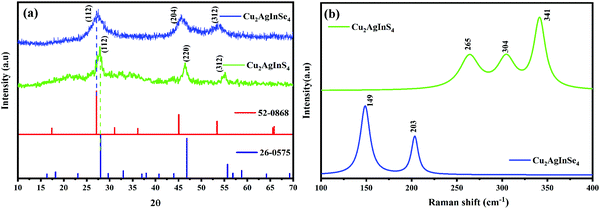
The XRD patterns of the synthesized CAIS and CAISe NPs are presented in Fig. 3a. This reveals a distinct tetragonal kesterite phase motif of CAIS, according to the JCPDS data (PDF #26-0575),14,18 with the most prominent characteristic and broadened reflections found at 28.4°, 47.8°, and 56.2° corresponding to the (112), (220) and (312) planes, respectively. At the same time, the peaks located around 2θ = 27.3°, 45.5° and 53.5° are consistent with the (112), (204) and (312) planes of the tetragonal kesterite phase of CAISe, according to the JCPDS data (PDF #56-0868).22Fig. 3b shows the Raman spectra of the CAIS and CAISe NPs. The peak at around 340 cm−1 corresponds to the A1 vibrational mode of the CAIS molecule, where the anions vibrate towards the z-axis. The peaks at around 265 cm−1 and 304 cm−1 correspond to the E vibrational modes of the kesterite crystal structure of Cu2AgInS4.26–28 The peaks at 203 cm−1 and 149 cm−1 correspond to the CAISe NPs.29 No other secondary phase peaks corresponding to Cu2Se (345 cm−1) or Ag2Se (176 cm−1) were observed, indicating the high purity.22
TEM images shown in Fig. 4a and d reveal that the synthesized CAIS and CAISe NPs are spherical in nature. The particle size distribution curves shown in the insets of Fig. 4a and d show that the average size of the particles are ∼20 and 27 nm for the CAIS and CAISe NPs, respectively. The CAIS NPs are more highly monodispersed than in the CAISe NPs system. Fig. 4b and e show HRTEM images and the nanocrystals are marked with yellow dotted circles. The distance between the lattice fringes is shown as 3.2 Å in Fig. 4b, corresponding to the (112) plane of the CAIS NPs. In Fig. 4e, the distances between the lattice fringes are shown to be 3.2 and 2.9 Å, corresponding to the (112) and (204) planes of the CAISe NPs, respectively. The polycrystalline nature of the synthesized CAIS and CAISe NPs is confirmed by a selected area electron diffraction (SAED) pattern (Fig. 4c and f). The Debye–Scherrer concentric rings correspond to the (112), (220), and (312) planes, and the (112), (204), and (312) planes, which correspond to the CAIS and CAISe NPs, respectively. According to the analysis above, the synthesized CAIS and CAISe NPs have good crystalline structure and are of high phase purity. The synthesized CAIS and CAISe NPs are dispersed well in chloroform to form colloidal CAIS and CAISe NPs. Each pearl carbon coated FTO was dipped separately into the colloidal solutions to deposit the CAIS and CAISe NPs onto the pearl carbon CEs. These will serve as hole transport materials for carbon electrode-based perovskite solar cells.
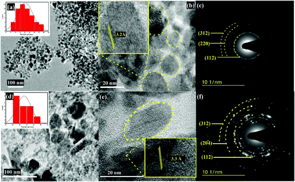 | ||
| Fig. 4 (a) TEM image, (b) HR-TEM image and (c) SAED pattern of the CAIS NPs, and the (d) TEM image, (e) HR-TEM image and (f) SAED pattern of the CAISe NPs. | ||
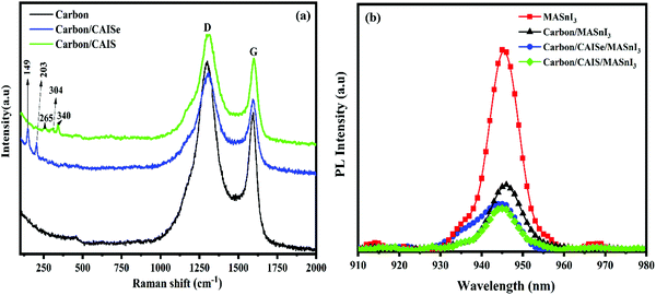
Fig. 5a shows the Raman spectra of the CAIS and CAISe NPs deposited on pearl carbon. The spectra show that the peaks at around 1310 cm−1 and 1600 cm−1 correspond to the D and G bands of a carbon atom. The peaks around at 340 cm−1, 265 cm−1 and 304 cm−1 correspond to the A1 and E vibrational modes of the CAIS molecule. The peaks at around 265 cm−1 and 304 cm−1 correspond to the E vibrational modes of the kesterite crystal structure of Cu2AgInS4.26–28 The presence of D and G bands and the respective Raman shifts confirmed the successful deposition of CAIS and CAISe NPs onto each of the pearl carbon CEs.
In order to evaluate the hole extraction and charge transport behaviours of CAIS and CAISe NPs deposited on pearl carbon CE, steady-state photoluminescence (PL) was carried out. Fig. 5b shows the normalized PL spectra of the perovskite, perovskite/pearl carbon and perovskite/pearl carbon with the CAIS and CAISe NPs. A strong PL peak at around ∼950 nm was found in the pristine perovskite layer, and this is consistent with the previously reported emission data.21,30–32 After deposition of the pearl carbon CE on the perovskite layer, the PL intensity was noticeably reduced, revealing that extraction of the charge carriers is improved. For the perovskites (MASnI3) deposited on pearl carbon with CAIS NPs and on pearl carbon with CAISe NPs, the PL intensities were decreased compared to the pearl carbon/perovskite and perovskite alone samples. This analysis indicates that the CAIS and CAISe NPs can enhance the hole extraction from the perovskite layer.33,34 This confirmed that the pearl carbon CE with CAIS NPs is more efficient in extracting the charge carriers than the bare carbon, increasing the Jsc value.11,35
In order to investigate the charge transport properties and recombination processes of perovskite/pearl carbon, perovskite/pearl carbon with CAIS NPs and perovskite/pearl carbon with CAISe NPs, electrochemical impedance analysis was performed from 100 kHz to 1 mHz under dark conditions at different biases. Fig. 6 shows the Nyquist plots of the PSC devices with the pearl carbon CE, the pearl carbon CE with the CAIS NPs, and the pearl carbon CE with the CAISe NPs. A typical Nyquist plot has two semicircles at high and low frequencies.36 The semicircle at the high frequency can be assigned to the charge transport through the device. The low frequency semicircle represents the charge recombination process in the device.37 A large semicircle at a lower frequency region is due to the resistance of charge recombination between the perovskite/carbon CE, the perovskite/pearl carbon CE with CAIS NPs and the perovskite/pearl carbon CE with CAISe NPs. The recombination resistance (Rrec) values for the devices fabricated with a pearl carbon CE, a pearl carbon CE with CAIS NPs and a pearl carbon CE with CAISe NPs were found to be 135, 629 and 414 Ω, respectively, at 0.8 V. The recombination rate is inversely proportional to Rrec,37,38 according to the fact that the device fabricated from pearl carbon with CAIS NPs as the CE has a much lower recombination rate. This proves that quaternary semiconducting NPs in a pearl carbon CE increase the charge recombination rate and may influence the PCE of PSCs.
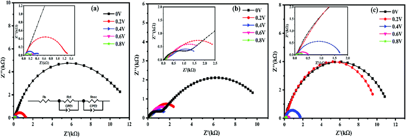 | ||
| Fig. 6 Nyquist plots of the PSCs based on (a) a pearl carbon CE, (b) a pearl carbon with CAISe NPs CE and (c) a pearl carbon with CAIS NPs CE under dark conditions at different biases. | ||
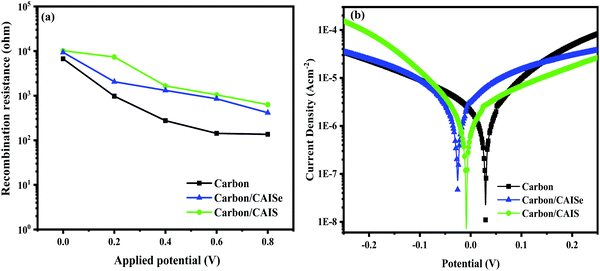
Fig. 7a shows the comparison of recombination resistance, Rrec, of PSCs using pearl carbon, pearl carbon with CAIS NPs and pearl carbon with CAISe NPs as CEs, at different biases. The result indicates that the order of Rrec is reduced when bias voltage is increased. It also reveals that a pearl carbon with CAIS NPs CE-based device has a higher Rrec value than the other two systems, due to the reduction of detrimental back electrons at the perovskite interface. Fig. 7b shows the Tafel polarization curves of PSC devices fabricated from pearl carbon and pearl carbon with CAIS NPs CEs. The experiment was conducted in dark conditions to evaluate charge carrier loss through the leakage pathway and the recombination of free carriers of the device during operating conditions.39 The leakage current density (J0) is obtained by the intersection of the extrapolated linear anodic or cathodic branches in the Tafel zone.40 These values are found to be in the following order: pearl carbon with CAIS NPs CE (2.63 × 10⁻⁶ A cm−2) < pearl carbon with CAISe NPs CE (5.72 × 10⁻⁶ A cm−2) < pearl carbon CE (7.85 × 10⁻⁶ A cm−2). The leakage current, J0, of the PSC fabricated from a pearl carbon CE with CAIS NPs is noticeably reduced, and this is due to an increase in the recombination resistance with decreased recombination rate at the interface of the perovskite. The lower leakage dark current suggests improved charge transport and decreased recombination loss of the devices. These outcomes are consistent with the analyses of EIS and PCE.
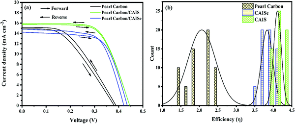
Perovskite solar cells were fabricated using a TiO2 thin film deposited by an ASG assisted pyrolysis method as the ETL, a MASnI3 thin film as the light absorber, and pearl carbon and pearl carbon with CAIS and CAISe NPs as the CEs. The current density–voltage (J–V) characteristics of the PSCs based on a pearl carbon CE and pearl carbon with CAIS and CAISe NPs as the CEs were studied under AM 1.5G irradiation at 100 mW cm−2, and the results are shown in Fig. 8. The control device with a pearl carbon CE had a PCE of 2.69% at the reverse scan and a PCE of 2.46% at the forward scan. According to Zhao et al. and Jiang et al., the hysteresis index (HI) for the PSC is calculated by the formula given,41,42
| HI = ((PCEreverse − PCEforward)/PCEreverse) × 100 |
4. Conclusion
CAISe and CAIS NPs were synthesised successfully by a hot injection method and their crystal structures were confirmed by XRD and Raman spectroscopy analysis. The synthesised CAISe and CAIS NPs were successfully deposited over separate pearl carbon CEs by immersing each pearl carbon CE in CAISe and CAIS NP colloidal solutions for 24 h. The influence of the pearl carbon with the CAISe and CAIS NPs as CEs was also studied. The enhancement in the charge transport nature and charge extracting behaviour of pearl carbon with CAISe and of pearl carbon with CAIS NPs as CEs was confirmed by steady-state PL analysis. According to electrochemical analysis, pearl carbon with CAIS NPs as the CE has enhanced charge transport with high recombination resistance. Under optimized conditions, the highest PCE of 4.24% with ∼57% enhancement could be obtained for the PSC based on pearl carbon with CAIS NPs as a CE, compared to the PSC with just a pearl carbon CE. We believe that this work will attract much attention for the deep understanding of the working mechanism of PSCs, and these results revealed that pearl carbon with CAIS NPs as a CE could be used as a potential CE in perovskite solar cell applications.Conflicts of interest
The authors declare that there is no conflict of interest.Acknowledgements
Dr A. S. gratefully acknowledge the Council of Scientific and Industrial Research (CSIR), New Delhi (Ref. No. 01(2810)14/EMR-II, dt. 26/04/2017) and the UGC-BSR-Mid Career Award (No. F.19-214/2018(BSR)) for their financial supports. The authors also acknowledge the Central Instrumentation Facility, Pondicherry University, for extending their instrumentation facility.References
- N. R. E. Laboratory, Best Research-Cell Efficiency Chart, https://www.nrel.gov/pv/cell-efficiency.html, accessed 04-06-2020, 2020.
- M. Wang, W. Li, H. Wang, K. Yang, X. Hu, K. Sun, S. Lu and Z. Zang, Adv. Electron. Mater., 2020, 6, 2000604 CrossRef CAS.
- G. Yang, H. Tao, P. Qin, W. Ke and G. Fang, J. Mater. Chem. A, 2016, 4, 3970–3990 RSC.
- M. Wang, H. Wang, W. Li, X. Hu, K. Sun and Z. Zang, J. Mater. Chem. A, 2019, 7, 26421–26428 RSC.
- X. Hu, H. Wang, M. Wang and Z. Zang, Sol. Energy, 2020, 206, 816–825 CrossRef CAS.
- M. Wang, Z. Zang, B. Yang, X. Hu, K. Sun and L. Sun, Sol. Energy Mater. Sol. Cells, 2018, 185, 117–123 CrossRef CAS.
- Z. Li, Y. Zhao, Y. Li, Q. Chen, Z. Li, Y. Zhao, X. Wang, Y. Sun, Z. Zhao, Y. Li and H. Zhou, Joule, 2018, 2, 1559–1572 CrossRef CAS.
- N. L. Chang, A. W. Yi Ho-Baillie, P. A. Basore, T. L. Young, R. Evans and R. J. Egan, Prog. Photovolt. Res. Appl., 2017, 25, 390–405 CrossRef.
- R. Hu, L. Chu, J. Zhang, X. A. Li and W. Huang, J. Power Sources, 2017, 361, 259–275 CrossRef CAS.
- L. Chu, W. Liu, Z. Qin, R. Zhang, R. Hu, J. Yang, J. Yang and X. A. Li, Sol. Energy Mater. Sol. Cells, 2018, 178, 164–169 CrossRef CAS.
- R. Hu, R. Zhang, Y. Ma, W. Liu, L. Chu, W. Mao, J. Zhang, J. Yang, Y. Pu and X. A. Li, Appl. Surf. Sci., 2018, 462, 840–846 CrossRef CAS.
- Y. Zhang, X. Zhuang, K. Zhou, C. Cai, Z. Hu, J. Zhang and Y. Zhu, Org. Electron., 2018, 52, 159–164 CrossRef CAS.
- J. Y. Kim, W. Baek, S. Kim, G. Kang, I. K. Han, T. Hyeon and M. Park, Appl. Surf. Sci., 2019, 496, 143610 CrossRef CAS.
- J. Kim, J. Kim, E. Ko, S. Yoon, J. H. Sim, K. J. Yang, D. H. Kim, J. K. Kang, Y. J. Song, C. W. Jeon and W. Jo, Prog. Photovolt. Res. Appl., 2020, 28, 382–392 CrossRef CAS.
- S. Ma, L. Dong, H. Dong, J. Wang, Y. Chen, B. Pang, J. Feng, L. Yu and M. Zhao, J. Colloid Interface Sci., 2019, 539, 598–608 CrossRef CAS PubMed.
- Y. H. Khattak, F. Baig, H. Toura, S. Beg and B. M. Soucase, J. Electron. Mater., 2019, 48, 5723–5733 CrossRef CAS.
- F. Li, C. Zhang, J. H. Huang, H. Fan, H. Wang, P. Wang, C. Zhan, C. M. Liu, X. Li, L. M. Yang, Y. Song and K. J. Jiang, Angew. Chem., Int. Ed., 2019, 58, 6688–6692 CrossRef CAS PubMed.
- Q. Wu, C. Xue, Y. Li, P. Zhou, W. Liu, J. Zhu, S. Dai, C. Zhu and S. Yang, ACS Appl. Mater. Interfaces, 2015, 7, 28466–28473 CrossRef CAS PubMed.
- M. Yuan, X. Zhang, J. Kong, W. Zhou, Z. Zhou, Q. Tian, Y. Meng, S. Wu and D. Kou, Electrochim. Acta, 2016, 215, 374–379 CrossRef CAS.
- Y. Zhang, Z. Zhang, Y. Liu, Y. Liu, H. Gao and Y. Mao, Org. Electron., 2019, 67, 168–174 CrossRef CAS.
- C.-M. Tsai, H.-P. Wu, S.-T. Chang, C.-F. Huang, C.-H. Wang, S. Narra, Y.-W. Yang, C.-L. Wang, C.-H. Hung and E. W.-G. Diau, ACS Energy Lett., 2016, 1, 1086–1093 CrossRef CAS.
- R. Kottayi, P. Panneerselvam, V. Murugadoss, R. Sittaramane and S. Angaiah, Sol. Energy, 2020, 199, 317–325 CrossRef CAS.
- R. Kottayi, P. Panneerselvam, N. Singh, V. Murugadoss, R. Sittaramane and S. Angaiah, New J. Chem., 2020, 44, 13148 RSC.
- K.-M. Lee, C.-J. Lin, B.-Y. Liou, S.-M. Yu, C.-C. Hsu, V. Suryanarayanan and M.-C. Wu, Sol. Energy Mater. Sol. Cells, 2017, 172, 368–375 CrossRef CAS.
- N. Cheng, P. Liu, S. Bai, Z. Yu, W. Liu, S. S. Guo and X. Z. Zhao, J. Power Sources, 2016, 321, 71–75 CrossRef CAS.
- O. Stroyuk, A. Raevskaya, O. Selyshchev, V. Dzhagan, N. Gaponik, D. R. T. Zahn and A. Eychmüller, Sci. Rep., 2018, 8, 1–10 CAS.
- M. Guc, S. Levcenko, I. V. Bodnar, V. Izquierdo-roca, X. Fontane, L. V. Volkova, E. Arushanov and A. Pérez-rodríguez, Sci. Rep., 2016, 6, 19414 CrossRef CAS PubMed.
- A. Krishnan, K. R. Ali, G. Vishnu and P. Kannan, Mater. Renew. Sustain. Energy, 2019, 8, 1–8 CrossRef.
- M. Dimitrievska, F. Oliva, M. Guc, S. Giraldo, E. Saucedo, P. Alejandro and V. Izquierdo-roca, J. Mater. Chem. A, 2019, 7, 13293–13304 RSC.
- W. Ke, C. C. Stoumpos, I. Spanopoulos, L. Mao, M. Chen, M. R. Wasielewski and M. G. Kanatzidis, J. Am. Chem. Soc., 2017, 139, 14800–14806 CrossRef CAS PubMed.
- H. Do, K. Un and F. D. Sno, Chem. Lett., 2017, 46, 253–256 CrossRef.
- T. Handa, T. Yamada, H. Kubota, S. Ise, Y. Miyamoto and Y. Kanemitsu, J. Phys. Chem. C, 2017, 121, 16158–16165 CrossRef CAS.
- X. Liu, X. Tan, Z. Liu, H. Ye, B. Sun, T. Shi, Z. Tang and G. Liao, Nano Energy, 2019, 56, 184–195 CrossRef CAS.
- P. Fassl, Y. Zakharko, L. M. Falk, K. P. Goetz, F. Paulus, A. D. Taylor and Y. Vaynzof, J. Mater. Chem. C, 2019, 7, 5285–5292 RSC.
- S. Sajid, A. M. Elseman, D. Wei, J. Ji, S. Dou, H. Huang, P. Cui and M. Li, Nano Energy, 2019, 55, 470–476 CrossRef CAS.
- H. Liu, X. Fu, W. Fu, B. B. Zong, L. Huang, H. Bala, S. Wang, Z. Guo, G. Sun, J. Cao and Z. Zhang, Org. Electron., 2018, 59, 253–259 CrossRef CAS.
- W. Ke, C. C. Stoumpos, I. Spanopoulos, M. Chen, M. R. Wasielewski and M. G. Kanatzidis, ACS Energy Lett., 2018, 3, 1470–1476 CrossRef CAS.
- C. Raminafshar, V. Dracopoulos, M. R. Mohammadi and P. Lianos, Electrochim. Acta, 2018, 276, 261–267 CrossRef CAS.
- H. Zou, D. Guo, B. He, J. Yu and K. Fan, Appl. Surf. Sci., 2018, 430, 625–631 CrossRef CAS.
- V. Murugadoss, P. Panneerselvam, C. Yan, Z. Guo and S. Angaiah, Electrochim. Acta, 2019, 312, 157–167 CrossRef CAS.
- Q. Jiang, Z. Chu, P. Wang, X. Yang, H. Liu, Y. Wang, Z. Yin, J. Wu, X. Zhang and J. You, Adv. Mater., 2017, 29, 1703852 CrossRef PubMed.
- Y. Zhao, J. Wei, H. Li, Y. Yan, W. Zhou, D. Yu and Q. Zhao, Nat. Commun., 2016, 7, 1–9 Search PubMed.
- G. Tumen-Ulzii, T. Matsushima, D. Klotz, M. R. Leyden, P. Wang, C. Qin, J.-W. Lee, S.-J. Lee, Y. Yang and C. Adachi, Commun. Mater., 2020, 1, 31 CrossRef.
- I. Zimmermann, P. Gratia, D. Martineau, G. Grancini, J.-N. Audinot, T. Wirtz and M. K. Nazeeruddin, J. Mater. Chem. A, 2019, 7, 8073–8077 RSC.
- F. Wu, R. Pathak, C. Chen, Y. Tong, H. Xu, T. Zhang, R. Jian, X. Li and Q. Qiao, Electrochim. Acta, 2020, 354, 1366603 Search PubMed.
Footnote |
| † Electronic supplementary information (ESI) available. See DOI: 10.1039/d0nj04175k |
| This journal is © The Royal Society of Chemistry and the Centre National de la Recherche Scientifique 2021 |

