 Open Access Article
Recent advances in Pt-based electrocatalysts for PEMFCs
Xuewei Zhang†
ab,
Haiou Li
ab,
Jian Yang†
a,
Yijie Lei
a,
Cheng Wang
 *a,
Jianlong Wang
 a,
Yaping Tanga and
Zongqiang Maoa
aWeichai Power Intelligent Manufacturing Joint Research Institute, INET, Tsinghua University, Beijing, China
bWeichai Power Co., Ltd., Weifang, 261061, Shandong, China
First published on 16th April 2021
Abstract
In order to reduce the cost and improve the performance of proton exchange membrane fuel cells (PEMFCs), it is imperative to further enhance the activity and durability of Pt based electrocatalysts for the oxygen reduction reaction (ORR). This article analyzes the latest advances in Pt-based ORR electrocatalysts, including the Pt alloys, Pt–M core–shell structures, particle size effects, support effects, doping in Pt/PtM and post treatment. In addition, the performance of some of the developed novel electrocatalysts in membrane electrode assemblies (MEA) is also included for comparison, as they are rarely available and the superior activity and durability exhibited in RDE frequently doesn't translate into MEA.
1. Introduction
Following the Paris Climate Agreement, countries around the world are gearing up their efforts to accelerate the decarbonization of vehicular transportation. Many countries and regions have announced the countdown for the ban of vehicles with internal combustion engines (ICE). With the development of lithium ion battery technology, light-weight battery electric vehicles (BEV) have been successfully commercialized in regions of mild climate.1,2 However, issues on energy density, cycle life, environmental compatibility, cost and safety, etc., restrict their wide-spread diffusion.3 Compared with lithium ion batteries, PEMFCs are energy conversion devices with high power density and superior climate compatibility.4–6 Fuel cell systems with high pressure H2 tanks have much higher energy density than the battery system. All these properties make PEMFCs particularly suitable as the main power source for cars, buses and trucks in all climates. Hence, fuel cell vehicles (FCVs) are widely regarded as the ultimate solution for the automotive industry.7,8 Toyota's Mirai, officially launched in Japan on December 15, 2014, is the first mass-produced FCV. Due to its excessive cost, global sales have only exceeded 9000 after more than five years. One of the main reasons for the high price of Mirai is the high loading of Pt-based electrocatalyst in the fuel cell stack.9,10The electrocatalyst at cathode side determines the overall performance of PEMFCs, because the oxygen reduction reaction (ORR) at cathode is the most sluggish process.11–13 Although platinum-free electrocatalysts, such as non-noble transition metals, metal nitrides and nano carbon-based metal free electrocatalysts, have been studied for a long time, their poor performance and stability makes them unsuitable for commercial application in fuel cell for transportation for the foreseeable future.14–18 Platinum (Pt) is a critical element in catalysts used in many industrial applications because of its unique property to accelerate oxidation and reduction reactions. Platinum has also been widely studied as an electrocatalyst for hydrogen oxidation reaction (HOR) and ORR in fuel cell technology.19,20 At present, platinum nanoparticles, usually supported on carbon particles, are the only practical choice for PEMFCs because of their highest activity among all pure metals.21–25 Although platinum is an ideal electrocatalytic material, its scarcity and high cost limit large-scale commercialization.26–28 Therefore, in order to reduce the platinum loading without affecting the performance of the fuel cell, it is imperative to improve the activity and durability of electro-catalyst based on platinum. Some researchers have developed platinum group metal catalysts for proton exchange membrane fuel cells from catalyst design to electrode structure optimization, and also emphasized the influence of Pt alloy catalysis on performance.29,30 In addition, many efforts have focused on the optimization of platinum materials, including core–shell structure, morphology control, and optimization of the support etc.31,32
While rotating disc electrode (RDE) is the most widely used method to test the activity and durability of newly developed ORR catalyst, it is an unfortunate fact that the superior performance exhibited in RDE frequently does not translate to the performance in membrane-electrode-assembly (MEA), which are the final assessment. The discrepancy may be attributed to the differences in the electrolyte, the catalyst–electrode interface, the test protocol, or even the stability of the catalyst.33,34 To give a complete judgement of the merits of any newly developed catalysts, it is highly desirable to include the tests both in RDE and MEA environment.
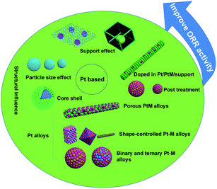
This article summarizes the latest advances in activity and durability of Pt-based catalysts in PEMFCs, with emphasis on Pt alloys, core–shell structures, particle size effects, support effects, PtM-MOF or MOF-derived, doping, post treatment and other factors (Fig. 1). The performance of some of the developed novel electrocatalysts in MEA is also included whenever it is available.
2. Pt alloys
Noble metal Pt nanoparticles have excellent ORR performance in fuel cells, but their low content and high cost seriously hinder their practical application. One of the potential strategies to solve this huge challenge is alloying platinum nanoparticles with transition metals. Compared with pure Pt, the ORR properties of Pt alloy NPs can be greatly improved due to the good electronic properties of transition metals and Pt alloying and the increase of the number of useful Pt sites.35,36 It has been widely reported that the formation of Pt-based alloys using various transition metals (such as Mn, Fe, Co, Ni, Cu, Zn) can enhance the activity of ORR. The specific activity of PtM (M = transition metal) has a volcanic relationship with the center of the d-band (Fig. 2). In PtM alloys, the electronic structure of Pt is modified by transition metal, tailoring its oxygen binding energy, thereby adjusting its ORR activity. Through DFT calculations and experimental studies, it is shown that the ORR activity of PtM (M = Co and Ni) is much better than any other PtM or Pt catalysts.37–41 At present, Pt3Co alloy catalyst is already used in Toyota's commercial fuel cell vehicle Mirai, while Pt3Ni alloy catalyst is being actively tested by General Motors. Further improvement in activity can be achieved through additional treatment of the alloy, such as dealloying, morphology control, multi-component, etc.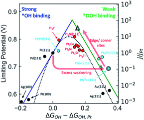 | ||
| Fig. 2 Comparison of the kinetic volcano (based on microkinetic modeling) with the limiting potential volcano (based on thermodynamic analyses), showing that both approaches are successful at predicting the experimentally observed activity trends for a range of materials. Reproduced with permission from ref. 37. Copyright © 2018, American Chemical Society. | ||
2.1 Porous Pt alloys
Porous Pt alloy structure, having a large number of exposed active sites, highly accessible surfaces and rapid mass transport, is a very effective structure.42,43 Dealloying is one of the most effective methods to prepare porous Pt alloy. In this process, amount of non-noble metals is selectively dissolved from the alloy by chemical or electrochemical methods. The dissolution of non-noble metals on the alloy surface produces defects and vacancies, exposing more active sites, making these sites more accessible.44,45 In several structure, for example, nanotubes, nanowire, nanofilm, nanocages, etc. can improve catalytic activity by the dealloying method.However, porous metal structures, usually existing in the form of nanoparticles, tend to aggregate or separate from supports (usually carbon), therefore showing poor stability.46–48 Porous one-dimensional nanostructures can solve these problems well.49 One dimensional nanostructure has anisotropic characteristics, which can have greater surface contact with the carbon support, resulting in high stability.50 Pippel et al.51 treated PtCo99, Pt4Ni96 and Pt30Co56Au, Pt5Cu76Co11Ni8 alloy nanotubes in 10 wt% H3PO4 with mild dealloying, and synthesized nanoporous Pt–Co, Pt–Ni, ternary Pt–Co–Au and quaternary Pt–Cu–Co–Ni alloy nanotubes (Fig. 3). These nanotubes, though ultra-low in Pt content, have significantly enhanced catalytic activity for ORR compared with commercial Pt black and Pt/C catalysts. In addition to the PtCo alloy nanowires, the PtFe alloy nanowires have also been extensively studied. Li et al.52 synthesized nano-porous Pt–Fe alloy nanowires by dealloying and studied their catalytic properties for ORR. The inhomogeneous composition of PtFe5 alloy nanowires prepared by electrospinning is helpful to the formation of nanoporous structure by dealloying, which exhibit more active and more durable than commercial Pt/C catalysts.
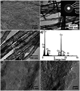 | ||
| Fig. 3 Structural characterization of the Pt5Cu76Co11Ni8 nanotubes. (a) Representative SEM micrograph of the nanotubes released from AAO membranes. (b and c) Typical TEM micrographs. Inset of (b): electron diffraction pattern. (d) EDX spectrum. (e and f) High-resolution TEM images. Reproduced with permission from ref. 51. Copyright © 2011 Wiley-VCH. | ||
The increase of the activity can be attributed to the lattice strain of the platinum skin surface formed by the surface dealloying and the modified electronic structure, which weakens the interaction between the atoms on the Pt surface and the intermediate species. Kim et al.53 relied on dealloying method to synthesize 3D nano-porous film structure catalyst. Since the dealloying has rich structural behaviors such as stress relief, the mass activity and specific activity of the nano-porous film structure catalyst are 1.7 times and 2.7 times higher than that of commercially available Pt/C.
Since the ORR performance of catalyst in half-cell is not enough to reflect its performance on single cell, it is necessary to design the MEA for testing. A bunched PtNi alloy nanocages (NCs) electrocatalyst was synthesized by Xia et al.54 The activity and stability of Pt–Ni bunched NCs (BNCs) were greatly improved compared with traditional catalysts. In addition, PtNi-BNCs/C is also tested in single cell, and the experimental results show that the peak power density is as high as 920 mW cm−2. The reason for this high performance is due to the combination of hollow structure and dimensional architecture in the bunched PtNi alloy NCs. In addition, More et al.55 also synthesized PtCo electrocatalyst, tested it in MEA, and made in-depth characterization before and after the accelerated stress test using electron microscopy, spectroscopy and 3D scanning electron microscopy. It is found that the morphology of PtCo nanoparticles with small sizes, which are usually rich in Pt under fresh conditions, had little change, while the PtCo nanoparticles with medium and large sizes had porous “sponge” morphology, initially with high Co content, which is due to the catalyst caused by continuous leaching of Co, converted to hollow shell.
2.2 Shape-controlled Pt alloys
The shape-controlled Pt alloys show excellent catalytic activity in PEMFCs. Due to the different geometry and electronic states of different crystal faces of nanoparticles, they have different catalytic properties for the same reaction. The surface structure of metal catalyst can be obtained by controlling the shape of metal nanoparticles. Synthesis conditions, such as reactant type and concentration, reaction time and temperature, can control the morphology of the final products.56 Based on this finding, Marković et al.57 showed that the crystal surface of Pt3Ni (111) can enhance the ORR activity, which is 10 times higher than that of Pt (111) and 90 times higher than that of commercial Pt/C catalyst. However, Zou et al.58 reported the synthesis of Pt3Ni (111) octahedra and Pt3Ni (100) cube with a high-temperature organic solution chemistry approach. The results show that the ORR activity of Pt3Ni octahedra is significantly higher than that of Pt3Ni cube (Fig. 4). According to the theoretical research, compared with (111) crystal surface, high index crystal surface such as (211) and (311) crystal surface is the most active surface with the best oxygen adsorption energy. PtFe nanodendrites with high index crystal surface were synthesized by Chen et al.59 They found that the ORR catalytic activity of nanostructures increased in the order of Pt/C < FePt nanospheres < FePt nanocubes < FePt nanodendrites. High resolution transmission electron microscope (HRTEM) images show that FePt nanodendrites have a high density of atomic steps with high-index {311} facet.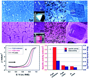 | ||
| Fig. 4 (a–e) Images for Pt3Ni octahedra. (f–j) Images for Pt3Ni cubes. (a and f) Field-emission SEM images. (b and g) High-resolution SEM images. (c) 3D image of an octahedral. (d and i) TEM images. (e and j) High-resolution TEM images of single NCs. (h) 3D image of a cube. (k) Polarization curves for ORR on Pt3Ni octahedra, Pt3Ni cubes, and Pt cubes. (l) comparison of the ORR activities on the three types of catalysts. Specific activity and mass activity were all measured at 0.9 V vs. RHE at 295 K. Reproduced with permission from ref. 58. Copyright © 2010 American Chemical Society. | ||
It can be seen from these examples that in recent years, the synthesis of shape-controlled alloy nanocrystals has made great progress in the RDE test. However, the destruction of the structural integrity, especially in the preparation of membrane electrode, remain a major setback in MEA test. Yan et al.60 used microwave-assisted solvothermal method to synthesize PtNi polyhedral alloy nanoparticles for PEMFCs. MEA tests were carried out in the Greenlight (G20) under H2/Air (1.8/2.5), cell temperature of 80 °C and active areas of 50 cm2 at 0.8 MPa, it is found that the power density can reach 400 mW cm−2 with the Pt loading of anode and cathode is 0.2 and 0.4 Pt mg cm−2. After 1000 and 5000 potential cycles, the decay rates of MEA prepared with PtNi/C were 1.5% and 3.0%, respectively.
2.3 Binary and ternary Pt alloys
The ORR activity of many kinds of binary PtM alloy nanoparticles was 2–10 times higher than that of pure Pt. For example, the hyperbranched nanostructures of PtNi alloy synthesized by Shen et al.61 can greatly improve the catalytic performance of ORR. Zhang et al.62 synthesized PtCo alloy catalyst with high active ORR by DMF coordination assisted electrodeposition. Ma et al.63 synthesized micro hexagonal nano PtFe alloy by simple synthesis method, which improved the electrocatalytic activity and durability of ORR. In addition to bimetallic alloy catalysts, ternary alloy catalysts have also been studied in recent years.64,65 The synergism of multi-component, strain and electronic effect can improve the catalytic activity. Abundant experiments have proved that compared with bimetal metal, ternary catalysts based alloy catalysts have further improved the catalytic performance of ORR.66,67 Iwasawa et al.68 synthesized PtCu and PtNiCu multinanorods. The specific activity and mass activity of PtNiCu multi-nanorods are 5 and 2 times higher than those of Pt/C respectively, which are also better than those of bimetallic PtCu catalysts. Due to the addition of Cu and Ni, the center of Pt d-band and the effect of compression strain (bond distance) are changed, which contribute to improve the ORR kinetics. Similarly, Zhang et al.69 synthesized PtCu, PtCuAg catalysts, of which PtCuAg/C (3![[thin space (1/6-em)]](https://www.rsc.org/images/entities/char_2009.gif) :
:![[thin space (1/6-em)]](https://www.rsc.org/images/entities/char_2009.gif) 10
10![[thin space (1/6-em)]](https://www.rsc.org/images/entities/char_2009.gif) :
:![[thin space (1/6-em)]](https://www.rsc.org/images/entities/char_2009.gif) 1) catalyst had the best ORR activity. The main reason for the increase of activity is that the addition of Ag causes the crystal distortion of Pt; CV cycle test dissolves CuO and Ag on the surface of alloy particles, which makes Pt atoms more exposed on the surface of alloy particles. In addition to traditional fcc PtM alloy catalysts, The design of highly ordered intermetallic compounds also has great application prospects in improving the activity and stability.70
1) catalyst had the best ORR activity. The main reason for the increase of activity is that the addition of Ag causes the crystal distortion of Pt; CV cycle test dissolves CuO and Ag on the surface of alloy particles, which makes Pt atoms more exposed on the surface of alloy particles. In addition to traditional fcc PtM alloy catalysts, The design of highly ordered intermetallic compounds also has great application prospects in improving the activity and stability.70
The dissolution of non-noble transition metals will lead to the degradation of PEMFCs performance, and the stability of PtM alloys may be lower than that of pure platinum. One solution to this problem is to alloy platinum with other precious metals such as palladium (Pd). Since Pd and Pt have similar crystal structure and electronic properties, yet the cost of Pd is relatively low, therefore Pd and Pt alloying is expected to significantly reduce the load of platinum while maintaining high catalytic activity, hence constitute a promising candidate for the ORR catalyst.71 Park et al.72 reported octahedra Pt3Pd1/C has exhibited much improved ORR electrocatalytic activity and stability. The increase of activity is due to the change of electronic structure of PtPd alloy catalyst compared with pure Pt. Moreover, the {111} plane is dominant in the octahedral structure formed by Pt and Pd. In PtPd–M system, the catalytic property of ternary alloy is also better than that of single and binary metal catalyst. Pd and M atoms jointly modify the electronic structure of Pt and regulate the morphology of catalyst, so as to improve the catalytic activity. Li et al.73 designed the best ternary catalyst Pt45Pd30Cu25/C with mass activity of 0.47 A mgPt+Pd−1, which is 2.35 times of that of commercial Pt/C (0.2 A mgPt−1). Coutanceau et al.74 synthesized ternary Pt70Pd15Au15/C and Pt50Pd25Au25/C by adding Pd and Au into Pt. These catalysts improved the catalytic activity of ORR.
The same strategy for alloying Pt is applied to MEA test. In many alloy strategies, PtCo alloy optimization may be applied to commercialization. Kim et al.75 used current pulse electrodeposition technology to synthesize PtCo cathode catalyst with the best ratio in PEMFCs. The chemical composition of the electrode can be controlled by changing the concentration of Co precursor, so as to find the best component ratio of catalytic activity. The current density of pulse electrodeposition electrode and conventional electrode at 0.6 V is 1.051 A cm−2 and 0.858 A cm−2, respectively. Hacker et al.76 proposed an economical PtCo/C alloy catalyst preparation method. In contrast, the PtCo/C MEA at a high temperature showed the same performance as the commercial Pt/C MEA at 600 h under constant load, while the PtCo catalyst had a significantly lower Pt loading.
3. Structural influence
3.1 Pt–M core–shell
Under acidic conditions, non-platinum metals in Pt alloys are easily dissolved from the surface of the alloy under electrochemical tests, which leads to the instability of the platinum alloys catalyst structure and affects the activity of the catalyst. For core–shell structure, the platinum or platinum alloy thin shell is deposited on the non-platinum NP core, which greatly reduces the amount of platinum. More importantly, the activity and durability of platinum shell can be adjusted by controlling the composition, size and shape of core–shell.77–79 Sugimoto et al.80 used monatomic metal nanoparticles as the core to make the highest utilization rate and the smallest nuclear size possible, resulting in a higher surface area than typical nanoparticle catalysts. The combination of large surface area and core–shell structure provides high ORR activity, hydrogen oxidation activity and CO tolerance.Adjusting the synthesis shell thickness of noble metal core–shell nanoparticles is an effective way to improve catalyst activity. For example, Sun et al.81 compared the activity by precisely adjusting the size of Pd core and the thickness of FePt shell. Petkov et al.82 synthesized Mn core of about 3 nm to adjust the thickness of Pt shell. Electrocatalytic measurement showed that the activity of ORR was 14–16 times higher than that of pure Pt. In addition to the influence of shell thickness on the activity, the structure of core materials, including the shape and particle size, also has an important influence on the ORR activity of core–shell catalysts. Xia et al.83 found that the specific activity of Pd octahedra rich in {111} is one order of magnitude lower than that of Pd octahedra rich in {100} in HClO4 solution. The specific activity of Pt shell on Pd octahedra is 28 times higher than that of Pd octahedra. The deposition of Pt shell did not improve the specific activity of Pd cube.
Due to the mismatch of lattice constant, compressive strain or tensile strain will be produced when Pt is deposited on the outer surface. The existence of strain affects the d-band center of Pt. There is a strong correlation between the binding energy of adsorbate and the center of d-band. In addition, the electron coupling between Pt and substrate results in additional electron (ligand) effect. Density functional theory (DFT) confirmed the strain effect and ligand effect, and revealed their role in controlling the electrocatalytic activity of Pt.84,85 Nilsson et al.86 found that surface strain can be used to adjust the activity of Pt based core–shell nanoparticles, providing a general strategy for the regulation of catalyst performance. The strain form of platinum rich surface layer (shell) is supported on the core of alloy particles with smaller lattice parameters. The compression in the shell changes the d-band structure of Pt atom, which weakens the adsorption energy of the reaction intermediate and improves the catalytic activity. The existence of biaxial strain can effectively improve the catalytic activity. Huang et al.87 latest found that biaxial strain PtPb/Pt core–shell nanoplates promote oxygen reduction catalysis. DFT calculations show that the PtPb/Pt nanoplate in the core–shell catalyst exhibit tensile stress in some directions and compressive stress in other directions. Therefore, some surface sites are in proper compression and play a major role in ORR. These catalysts can withstand 50![[thin space (1/6-em)]](https://www.rsc.org/images/entities/char_2009.gif) 000 voltage cycles, with negligible activity decay and no significant structural and compositional changes.
000 voltage cycles, with negligible activity decay and no significant structural and compositional changes.
It is very necessary to find the best combination of core/shell materials with excellent ORR activity through experiments and theoretical calculations. Lu et al.88 proposed a multi-scale computing strategy to design Ru@Pt core–shell nanoparticles. The surface strain can be accurately determined by quantum mechanics (QM) calculation, and the general relationship between the surface strain of core/shell nanoparticles and the surface oxygen adsorption energy is established. The Ru@Pt nanocomposite catalyst they synthesized is very stable under both cathode and anode conditions, showing higher durability than typical commercial catalysts (Fig. 5). In addition, Adzic et al.89 compared the ORR activity of Pt deposited on different substrates (Ir, Ru, Rh, Pd, Au). It was found that the strong correlation between the activity and the d-band center of Pt was mainly determined by the type of substrate.
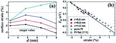 | ||
| Fig. 5 Surface strain on the core/shell nanoparticles. (a) Lateral strain on the (111) facet of the Pt–Cu core/shell and the pure Pt nanoparticles. The lower horizontal line indicates the target strain value for an optimal ORR activity. (b) Correlation between E0 and the surface strain for the nanoparticles and the Pt flat surface. There exists a universal linear relation between E0 and the strain. Reproduced with permission from ref. 88. Copyright © 2013 American Chemical Society. | ||
3.2 Particle size effect
Compared with structural sensitivity, the effect of Pt particle size on ORR activity is a long-standing controversy. Some studies reported that the average particle size of the maximum specific activity of platinum reached 3–5 nm, while others found that the specific activity of platinum increased linearly with the decrease of the particle size.90 Su et al.91 for instance, found that the best choice for the activity and durability of Pt/C electrocatalyst is that the average Pt particle size is about 4 nm. Strasser et al.92 found that PtNi3 NP with initial particle size of 6–8 nm showed the highest activity under the condition of acid ORR. Some studies even report that there is little or no particle size effect in ORR within a specific size range.93 Wieckowski et al.94 found that the particle size of platinum synthesized by controlling conditions was 1–5 nm. The results showed that in HClO4 solution, when the particle size increased to 2.2 nm, the specific activity of ORR increased rapidly, but the further increase of particle size had little effect on the activity. Other researchers believe that specific activity does not depend on particle size, but on the dispersion between particles. Recent studies by Sonoi et al.95 show that the specific activity of Pt increases with the decrease of particle size, and the specific activity of 0.9 nm cluster is more than 10 times higher than that of 2.5 nm cluster.If other parameters (annealing temperature, shape, composition, electrolyte solutions etc.) change at the same time besides particle size, it is difficult to draw a meaningful conclusion.96–99 Precise control of variables makes the experiment persuasive. Thus, a more accurate relationship between particle size and catalytic performance should be established.100 Arenz et al.101 studied the effect of Pt NPs size on ORR in different electrolyte solutions with different anion adsorption strength. The relationship between activity and particle size is rather independent of the supporting electrolyte. The model predicts that the specific surface area decreases linearly with the increase of ECSA and the decrease of particle size in the two kinds of acid electrolytes. When the particle size is about 2.5 nm and ECSA is about 90 m2 g−1, it shows the maximum mass activity (Fig. 6). Peng et al.102 prepared octahedra Pt3Ni/C and Pt1.5Ni/C by solid-phase chemical method without surfactant, the particle size was between 4 nm and 8 nm, and realized the separated control of particle size and composition. The ORR activity of octahedra Pt3Ni/C increased monotonously with the increase of particle size, i.e., the ORR activity of 4.5 nm Pt3Ni/C was 2.47 mA cm−2, and that of 8.1 nm Pt3Ni/C was 4.06 mA cm−2 at 0.9 V vs. RHE. The significant change of ORR activity was attributed to the proportion change of (111) terraces, which was related to the size. Yang et al.103 synthesized different sizes of Pt3Co particles and the emphasis of this paper is to report a similar system analysis of Pt3Co catalyst with almost the same metal, but the average particle size is different, and to compare with Pt catalyst, in order to reveal the influence of alloying and particle size. The cathode performance of 8.1 nm Pt3Co is better than that of 4.9 nm Pt3Co.
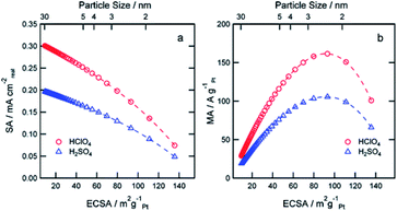 | ||
| Fig. 6 Simulation of expected SA (a) and MA (b) at 0.9 V RHE as a function of the ECSA for perchloric and sulfuric acid solutions. Reproduced with permission from ref. 101. Copyright © 2011 American Chemical Society. | ||
The influence of Pt particle size and operation conditions on the durability of PEMFCs cathode catalyst was studied by Gummalla et al.104 They found that the maximum particle size (∼12 nm) hardly changed the electrochemical surface area or mass activity in 10 K cycle, but the initial performance was lower in the high current region. The smaller Pt particles (∼2 nm) show good initial performance, including high mass activity and polarization, but the electrochemical surface area (ECSA) loss rate is also high. At 10 K cycle, the performance of ∼2 nm particles are lower than that of ∼12 nm particles. Interestingly, the 7 nm Pt particle used for MEA shows very good initial performance and very slow electrode degradation characteristics. The slow degradation is attributed to the stability of the particles, and the good performance is attributed to the proper particle size to increase the particle dispersion and surface area to support ORR.
4. Support effects
4.1 Carbon and graphene support
Carbon and graphene are two kinds of carbon support with enhanced conductivity and metal-support interaction, which can improve their catalytic activity and stability. Compared with commercial C, graphene (g) has the advantages of large specific surface area, high conductivity, good stability and strong interaction with nanoparticles. As a new natural support, it has been widely studied to improve the activity and durability of nanoparticles catalysts. At present, various synthesis strategies for preparing graphene supported nano catalysts as ORR catalysts have been examined. For example, the performance and durability of platinum catalyst can be improved by adjusting the balance between graphitization and hierarchical porosity.105Chemical modification of graphene inert surface is necessary for the uniform dispersion of nano particles in electrocatalyst. However, these processes may lead to the partial destruction of graphene structure, thus affecting the catalytic activity. Nitrogen doping in graphene can introduce chemical active sites to improve catalytic activity. For example, Zhang et al.106 prepared a three-dimensional mesoporous nitrogen doped graphene aerogel (NGA) by simple one-step co-assembly. The co-assembly of Pt NCs and NGA has large specific surface area (1750 m2 g−1), abundant mesopores and high nitrogen content (3.93 at%). The unique structure of Pt NCs@NGA not only ensures the exposure of active Pt NCs and reduces the diffusion time of O2 in the channel, but also increases the adsorption of O2 in Pt NCs@NGA, thus improving the rate of ORR. Shen et al.107 prepared boron nitrogen double doped graphene (BNG) film by one-step pyrolysis of nitrogen and boron-containing borane-tert-butylamine complex impregnated with cobalt ion. BNG skillfully anchored Pt nanoparticles to ensure excellent durability of Pt/BNG. B–N double doped graphene film has a good effect on the electron transport of Pt, which can promote the reduction of O2 and enhance the BNG/Pt interaction. Compared with the commercial Pt/C catalyst, the new Pt/BNG catalyst has greatly improved its electrocatalytic activity and stability in 0.1 m HClO4 with saturated O2. The mass activity of Pt/BNG catalyst at 0.9 V vs. RHE is 213.6 mA mgPt−1, nearly three times that of the commercial Pt/C catalyst (Fig. 7).
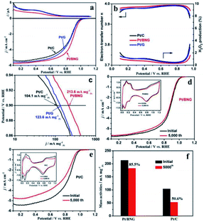 | ||
| Fig. 7 (a) Ring currents (up) and corresponding linear sweep curves (down) of commercial Pt/C, Pt/G and Pt/BNG catalysts for ORR, (b) electron-transfer number and calculated H2O2 production yields of the catalysts during the ORR, (c) mass activities for the ORR on catalysts, (d and e) polarization curves for the ORR on Pt/BNG and Pt/C electrode before and after 5000 cycles (insets are corresponding CVs of Pt/BNG and Pt/C) and (f) mass activities of the Pt/BNG and Pt/C catalysts after 5000 cycles. Reproduced with permission from ref. 107. Copyright © 2016 Elsevier Ltd. | ||
The MEA test of chemical modification of graphene also showed high catalytic activity. Ramaprabhu et al.108 designed a novel synthesis method to obtain nitrogen doping in hydrogen exfoliated graphene (HEG) sheets. At 60 °C, the maximum power densities of Pt3Co/C and Pt3Co/N-HEG cathodes were 379 and 805 mW cm−2 at 2 °C, respectively, without backpressure.
4.2 Titanium nitride support
Titanium nitride, one of the most popular transition metal nitrides, has been recognized as a high hardness and chemical stability due to its high melting point. Its special metal properties are attributed to the fact that a single unpaired electron enters the localized sp hybrid orbit in Ti, resulting in the non-zero electron density at the Fermi level, which makes it have high conductivity. At the same time, it is also a good choice as support. The calculation of DFT also proves the suitability of TiN as a catalyst support. A graded macroporous/mesoporous catalyst support with interconnected macroporous channels will be able to deliver fuel to the mesoporous interior region for reactions. Suntivich et al.109 used block copolymers to synthesize mesoporous TiN, and after 200 cycles of stability tests, TiN maintained conductivity in acidic electrolytes up to 1.4 V vs. RHE. In addition, some research groups can also show excellent stability and durability by using TiN based catalyst support. These reports usually focus on ORR activity and electrochemical stability tests to verify and quantify the potential of TiN as a catalyst support, while rarely testing the performance of MEA prepared with TiN as a catalyst support.There are also a lot of researches on the preparation of MEA about TiN support for testing. Perng et al.110 successfully prepared high surface area TiN macroporous/mesoporous structure by sol–gel method. The phase separation and nitriding of 2 h were carried out at 800 °C. The anti-opal structure of TiN was prepared by nitriding method. Polystyrene spheres (PS) multilayer films were prepared on carbon paper with atomic layer deposition (ALD) of nano TiO2 as template. Pt nanoparticles were prepared on TiN inverse opal by ALD method, covering and dispersing evenly. The loading capacity and particle size of platinum nanoparticles can be directly controlled by the number of ALD cycles. In the single-cell experiment, the specific power density of the Pt@TiN@CP electrode was 13 times higher than that of the commercial E-Tek electrode (Fig. 8).
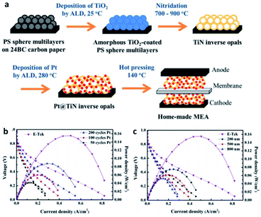 | ||
| Fig. 8 (a) Schematic of fabricating Pt@TiN@CP to form MEA for PEMFCs. MEA performances for home-made anodes with (b) Pt prepared by various cycle numbers of ALD on 500 nm TiN inverse opals and (c) Pt prepared by 100 ALD cycles on TiN inverse opals with different diameters. The commercial E-Tek anode is included for comparison. For all cases, E-Tek electrode is used as the cathode. Reproduced with permission from ref. 110. Copyright ©2017 Elsevier Ltd. | ||
4.3 Metal oxide support
Metal oxide support is an effective substitute for electrode catalyst because of its excellent mechanical strength, corrosion resistance and higher stability than carbon under various operating conditions. According to K. Ito111 theoretical calculation, titanium dioxide (TiO2) can be used as a candidate material for fuel cell catalyst. However, pure titanium dioxide is called semiconductor. Due to its high band gap and lack of conductivity, it is difficult to obtain the electrons of ORR by absorbing hydroxyl groups (OHs) on its surface. This is considered to be a major obstacle to the direct use of oxide materials as support materials. Therefore, researcher need a new effective cathode structure to induce platinum into active state and improve its conductivity. The surface can be wound by CNTs and Pt/TiO2 nanofibers. The introduction of TiO2 nanofibers helps to make it more durable due to its good stability and strong metal support interaction (SMSI) effect. Shul et al.112 studied a new effective structure to induce platinum to enter the active state and improve its conductivity. They have synthesized a composite electrode of Pt/TiO2 nanofibers (CNT Pt/TiO2) wound by carbon nanotubes (CNTs) (Fig. 9). The conductivity of TiO2 can be increased by doping a small amount of donor ions. For example, V. Krstajić et al.113 used Nb doped TiO2 as the support of Pt and Pt–Ru anode catalysts for PEMFCs. Through the cooperation of TiN and TiO2, electrical conductivity and corrosion resistance are improved. Besides, Li et al.114 also prepared Pt/TiN–TiO2 catalyst with TiN–TiO2 as support.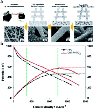 | ||
| Fig. 9 (a) Schematic diagram of CNT-Pt/TiO2 nanofibrous catalyst fabrication procedure and SEM images. From left, each image indicates PVP/Ti, TiO2, Pt/TiO2, and CNT-Pt/TiO2 nanofibers. (b) I–V curves test of the CNT-Pt/TiO2 (Tcell = 120 °C, RH 40%). Reproduced with permission from ref. 112. Copyright © 2016 Elsevier B.V. | ||
4.4 PtM-MOF and MOF-derived support
Through a series of processing methods, PtM (Ni Co Fe) materials can make organic ligands through Ni, Fe Co coordination to form MOFs structure. When the metal organic framework (MOFs) or porous organic polymer is used as the precursor, these catalysts have dense and uniform active sites on the whole electrode, which can easily obtain better O2 flux. However, its main disadvantage is poor stability under PEMFCs operation.115 The degradation of Pt catalyst is mainly caused by crystal dissolution and agglomeration. Unlike Pt catalyst, the origin of deactivation of platinum group metal (PGM)-free catalyst is poorly understood due to the controversial nature of active sites.116 One possible cause is oxidative degradation of hydrogen peroxide produced in the ORR process.117 If the ultra-low supported platinum and PGM-free metal catalysts compensate each other synergistically, the use of platinum will be greatly reduced, while maintaining good activity and durability. A. M. Kannan et al.118 have studied ZIF derived PtNiCo/NC cathode catalyst for PEMFCs. Under the conditions of 150 KPa, 70 °C and 100% RH with H2 and O2, the peak power density of PtNiCo/NC elctrocatalyst can reach up to 1070 mW cm−2 in single cell, which is 15% higher that of Pt catalyst under the same loading (Fig. 10). Liu et al.119 used cobalt or bimetallic cobalt and zinc zeolites imidazolites as precursors to prepare active and stable electrocatalysts containing ultralow-loading platinum.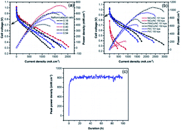 | ||
| Fig. 10 The PEMFCs performance of (a) Nafion/catalyst ratio optimization for PtNiCo/NC, (b) MEAs with NiCo/NC, PtNiCo/NC and Pt/C with/without back pressure, (c) the stability testing with PtNiCo/NC cathode at ambient pressure. (All the data were obtained at 70 °C, 100% relative humidity with H2 and O2 at 200 and 300 SCCM with Nafion 212 membrane.) Reproduced with permission from ref. 118. Copyright © 2019 Elsevier B.V. | ||
5. Doped in Pt/Pt–M/support
The doping of foreign atoms will change the oxygen binding energy near the center of the crystal surface. Due to these changes, some sites may become highly catalytic. Doping can fine tune the chemical and electronic properties of its surface layer, thus adjusting its catalytic activity. Chen et al.120 synthesized iron doped octahedra Pt3Ni nanocrystals. It was found that after 16![[thin space (1/6-em)]](https://www.rsc.org/images/entities/char_2009.gif) 000 potential cycles in acid medium, the octahedra shape was stable, and its mass activity decreased only about 25%. Huang et al.121 reported that the specific surface area activity of molybdenum-doped Pt–Ni octahedra nanoparticles is 10.3 mA cm−2, and the mass activity is 6.98 A mgPt−1, the loss of activity after 8000 potential cycles is only 5%. In addition, the application of doping strategy to MEA has also been studied by some researchers. Lee et al.122 prepared Au doped PtCo/C catalyst by simple gas reduction and current displacement method, and tested its activity and durability in a single cell (Fig. 11). The results show that the current density of Au doped PtCo/C catalyst can reach 1.63 A cm−2 at 0.6 V, while the current density of acid treated PtCo/C catalyst and commercial Pt/C catalyst are 1.31 and 1.20 A cm−2 at the same Pt load (0.2 mg cm−2), respectively. After the durability test, the current density at 0.6 V was reduced to 1.40, 0.81 and 0.63 A cm−2 through 30
000 potential cycles in acid medium, the octahedra shape was stable, and its mass activity decreased only about 25%. Huang et al.121 reported that the specific surface area activity of molybdenum-doped Pt–Ni octahedra nanoparticles is 10.3 mA cm−2, and the mass activity is 6.98 A mgPt−1, the loss of activity after 8000 potential cycles is only 5%. In addition, the application of doping strategy to MEA has also been studied by some researchers. Lee et al.122 prepared Au doped PtCo/C catalyst by simple gas reduction and current displacement method, and tested its activity and durability in a single cell (Fig. 11). The results show that the current density of Au doped PtCo/C catalyst can reach 1.63 A cm−2 at 0.6 V, while the current density of acid treated PtCo/C catalyst and commercial Pt/C catalyst are 1.31 and 1.20 A cm−2 at the same Pt load (0.2 mg cm−2), respectively. After the durability test, the current density at 0.6 V was reduced to 1.40, 0.81 and 0.63 A cm−2 through 30![[thin space (1/6-em)]](https://www.rsc.org/images/entities/char_2009.gif) 000 cycles of CV repeated in 0.6–1.0 V at 100 mV s−1, which can be seen that Au doped PtCo/C catalyst shows high activity and durability.
000 cycles of CV repeated in 0.6–1.0 V at 100 mV s−1, which can be seen that Au doped PtCo/C catalyst shows high activity and durability.
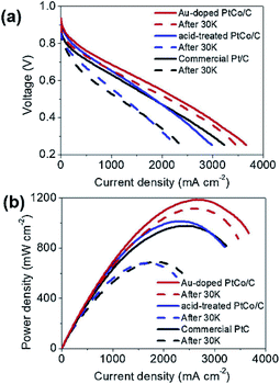 | ||
Fig. 11 I–V polarization curves of single-cells for the acid-treated PtCo/C, the Au-doped PtCo/C, and the commercial Pt/C catalysts. The initial performance is shown by solid lines and the performance after 30![[thin space (1/6-em)]](https://www.rsc.org/images/entities/char_2009.gif) 000 cycles is shown with dashed lines. The durability tests were conducted by repeating CVs in 0.6–1.0 V at 100 mV s−1 in Ar flow at the cathode with 100% RH. Reproduced with permission from ref. 122. Copyright © 2019 Elsevier B.V. 000 cycles is shown with dashed lines. The durability tests were conducted by repeating CVs in 0.6–1.0 V at 100 mV s−1 in Ar flow at the cathode with 100% RH. Reproduced with permission from ref. 122. Copyright © 2019 Elsevier B.V. | ||
A large number of studies have shown that the catalytic activity can also be improved by doping the support. The advantages of (P, N)-doped carbon as catalyst support may include: due to the development of pore structure, the dispersion and conductivity of catalyst are increased; due to the charge transfer from Pt to adjacent (P, N) atoms, the adhesion of Pt nanoparticles is enhanced, which is helpful for the decomposition of active intermediates such as hydrogen peroxide.123–125 Peng et al.126 study on oxygen reduction reaction of phosphorus doped carbon nanotubes supported low platinum catalyst in acid fuel cell. The electronic density of Pt atom on P-CNT support changes greatly, which leads to the significant increase of Pt/P-CNTs activity. The electrocatalytic activity of N-doped C supported Pt nanoparticles for oxygen reduction was significantly enhanced by Chen et al.127 The increase of ORR activity of Pt/NCB catalyst may be due to the spillover effect, which can be explained by the spillover effect of oxygen-containing substances on the migration of Pt to the C–N active center near the nitrogen doped carbon black (NCB), which will reduce the coverage of oxygen-containing substances on platinum. Generally, the redox peaks related to the formation and reduction of oxidation species are more reversible in the lower coverage. Kannan et al.128 pyrolyzed ZIF-67 with Pt precursor in flowing Ar and H2 atmosphere to synthesize PtCo@NCNTs (nitrogen doped carbon nanotubes) catalyst. The performance of PtCo@NCNTs in 0.1 M HClO4 is better than that of Pt/C catalyst. Nafion-212 electrolyte membrane, hydrogen and oxygen (100% RH) were used to evaluate the performance of PtCo@NCNTs and commercial Pt/C catalyst at 70 °C, and their power densities were 630 and 560 mW cm−2, respectively.
6. Post treatment
The heat treatment or activation of Pt based catalysts is a necessary step in the synthesis of Pt based catalysts, which has an important influence on surface morphology and the dispersion of metals on the supports. The advantage of heat treatment is to remove any undesirable impurities produced in the early preparation stage, so that the metal can be evenly distributed and stably distributed on the support, so as to improve the electrocatalytic activity of the synthetic catalyst. Moreover, heat treatment is considered as an important step to improve the catalytic activity and stability. The PEM fuel cell electrocatalysts are usually prepared by conventional stove/furnace heating, microwave heat treatment, plasma heat treatment and ultrasonic spray pyrolysis. Among them, the traditional stove heating technology is the most widely used. Generally speaking, it includes heating catalyst for 1–5 h in inert (N2, Ar or He) or reductive (H2) atmosphere in the temperature range of 80–800 °C.129–132Heat treatment changes the particle size, morphology, metal dispersion on the support, alloying degree, active center, catalytic activity and catalytic stability of metal catalysts. For example, Tammeveski et al.133 prepared platinum nanoparticles supported on multi-walled carbon nanotubes (Pt/MWCNT) electrode by magnetron sputtering and annealed in nitrogen atmosphere at different temperatures for 30 min. The results show that the nanoparticles size increases with the increase of annealing temperature. Moreover, at 400 °C, particles agglomerate. The results show that 300 °C is the best annealing temperature to improve the ORR activity of Pt/MWCNT electrocatalyst. Heat treatment under (Ar, N2, H2) atmosphere can protect the structure from damage to the maximum extent. Liu et al.134 for instance, prepared Pt NCs@CNTs catalyst and carried out heat treatment. In Ar or 20% H2–80% Ar atmosphere, the effect of heat treatment at different temperatures on activity and durability was studied. TEM images show that Pt NCS has a particle size of about 6 nm, and the particle size changes with the increase of heat treatment temperature. XPS analysis showed that the binding energy of Pt increased after heat treatment. In addition, 20% H2–80% Ar atmosphere is more favorable to improve the activity than pure Ar atmosphere. It was found that the oxygen reduction activity and durability of Pt NCs@CNTs catalyst were improved in the atmosphere of 300 °C and 20% H2–80% Ar. Kim et al.135 studied the effect of heat treatment at 300–700 °C for 3–9 h in H2 and N2 atmosphere on the preparation of 20% Pt/C catalyst. In order to compare, the catalyst was pretreated by repetitive potential cycling. The results show that the catalytic activity of heat treatment is better than that of repetitive potential cycling. In addition, SEM and XRD tests show that the average particle size increases linearly with heating time and exponentially with heating temperature. The surface morphology of the catalyst determines the activity of ORR, while the particle size has little effect on the activity of ORR.
The length of Pt–Pt bond can change the activity of ORR, and the smaller the Pt–Pt distance, the higher the catalytic activity.136 Heat treatment of alloy catalysts at temperatures higher than 700 °C can counteract each other: (1) better Pt–M alloy is formed, which reduces the Pt–Pt distance and affects the d-band vacancy of Pt, thus improving the electrical activity of Pt. (2) The catalyst particle size increases, and the catalyst particle size reduces the active area of Pt, resulting in the decrease of catalyst mass activity. Some studies have shown that the size of platinum particles changed by heat treatment can change the vacancy of d-band. According to the present study, the hybridization of 5d state with the vacancy state above Fermi level can reduce the number of d electrons. However, as the particle size increases, the hybrid will become less favorable.
Wang et al.137 realized structural transformation from disordered alloy to ordered intermetallic by heat treatment. Ozturk et al.138 found that the electronic structure of PtCo was changed and the alloying degree of PtCo was improved by heat treatment of PtCo catalyst at different temperatures. Hunsom et al.139 systematically studied the effect of heat treatment on the activity and stability of ORR (Fig. 12). It was found that compared with commercial Pt/C catalyst, heat treatment improved the alloying degree of PtCr catalyst, and made Cr atoms embedded in Pt structure, but reduced the dispersion of catalyst. The increase of heat treatment temperature from 500 °C to 900 °C increased the alloying degree, and the prepared catalyst particle size, Cr content and in-plane conductivity decreased, but the dispersion degree and ECSA of catalyst decreased. Among all the prepared catalysts, PtCr/C-500 shows high activity and stability, which can be used as cathode catalyst for fuel cell.
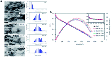 | ||
| Fig. 12 (a) Representative (left) TEM and (right) particle size distribution of the commercial Pt/C (ETEK) and as-prepared PtCr/C catalysts. (b) Representative current density potential and power density potential curves of the commercial Pt/C (ETEK) and as-prepared PtCr/C catalysts. Reproduced with permission from ref. 139. Copyright © 2018 Elsevier Ltd. | ||
7. Conclusions
Although significant progress has been made in the field of Pt free electrocatalysts, these materials still have some inherent defects in ORR. In the past, great progress has been made in the study of electrocatalysts based on platinum-based nanomaterials. The size, composition, morphology, porosity, surface structure, synthesis and post-treatment of Pt based materials play an important role in their activity and stability. In general, the activity of Pt based electrocatalyst can be improved through the following methods: (1) the alloying of Pt and transition metals can be used to increase the mass and specific activity of Pt atom. (2) Dealloying method could be used to form a porous structure to increase surface area and strain of the alloy catalysts. (3) Core–shell structure was formed to improve the utilization rate of platinum atom, and electronic properties were changed through strain of core and ligand effect. (4) Dispersion and conductivity of catalyst were improved through the optimization of the supports. Fluidity of oxygen and active site were increased through MOF treatment to improve catalytic activity. (5) Heat treatment has an important influence on the size and distribution of metal particles, the surface morphology of particles and the dispersion of metal on the support. Considering the difference between liquid acid electrolytes and MEA used in single cell tests with the solid electrolyte, the superior performance of new catalysts evaluated using half-cell electrochemical measurements does not necessarily translate into improved performance in MEA. Whether these new nanostructures catalysts can be used to prepare fuel cell MEA with superior performance to reduce the Pt load and cost is still challenging.Conflicts of interest
There are no conflicts to declare.Acknowledgements
This work was supported by the National Key R&D Program of China (No. 2018YFE0202000, No. 2016YFB0101200), the National Natural Science Foundation of China (No. 21773136, No. U1664259).Notes and references
- D. Larcher and J. M. Tarascon, Nat. Chem., 2015, 7, 19–29 CrossRef CAS PubMed.
- J. R. Szczech and S. Jin, Energy Environ. Sci., 2011, 4, 56–72 RSC.
- X. Pu, H. Wang, D. Zhao, H. Yang, X. Ai, S. Cao, Z. Chen and Y. Cao, Small, 2019, 15, 1805427 CrossRef PubMed.
- X. Lü, Y. Qu, Y. Wang, C. Qin and G. Liu, Energy Convers. Manage., 2018, 171, 1273–1291 CrossRef.
- W. Liu, Q. Ru, S. Zuo, S. Yang, J. Han and C. Yao, Appl. Surf. Sci., 2019, 469, 269–275 CrossRef CAS.
- Y.-J. Wang, W. Long, L. Wang, R. Yuan, A. Ignaszak, B. Fang and D. P. Wilkinson, Energy Environ. Sci., 2018, 11, 258–275 RSC.
- Y.-F. Guo, H.-C. Chen and F.-C. Wang, Int. J. Hydrogen Energy, 2015, 40, 4630–4640 CrossRef CAS.
- M. Liu, Z. Zhao, X. Duan and Y. Huang, Adv. Mater., 2019, 31, 1802234 CrossRef PubMed.
- T. Yoshida and K. Kojima, J. Electrochem. Soc., 2015, 24, 45–49 CAS.
- M. Shao, Q. Chang, J.-P. Dodelet and R. Chenitz, Chem. Rev., 2016, 116, 3594–3657 CrossRef CAS PubMed.
- S. Sui, X. Wang, X. Zhou, Y. Su, S. Riffat and C.-J. Liu, J. Mater. Chem. A, 2017, 5, 1808–1825 RSC.
- A. Morozan, P. Jégou, B. Jousselme and S. Palacin, Phys. Chem. Chem. Phys., 2011, 13, 21600–21607 RSC.
- Y.-J. Wang, W. Long, L. Wang, R. Yuan, A. Ignaszak, B. Fang and D. P. Wilkinson, Energy Environ. Sci., 2018, 11, 258–275 RSC.
- A. Morozan, B. Jousselme and S. Palacin, Energy Environ. Sci., 2011, 4, 1238–1254 RSC.
- W.-F. Chen, K. Sasaki, C. Ma, A. I. Frenkel, N. Marinkovic, J. T. Muckerman, Y. Zhu and R. R. Adzic, Angew. Chem., Int. Ed., 2012, 51, 6131–6135 CrossRef CAS PubMed.
- S. Liu, C. Deng, L. Yao, H. Zhong and H. Zhang, J. Power Sources, 2014, 269, 225–235 CrossRef CAS.
- N. Ranjbar Sahraie, J. P. Paraknowitsch, C. Göbel, A. Thomas and P. Strasser, J. Am. Chem. Soc., 2014, 136, 14486–14497 CrossRef CAS PubMed.
- T.-F. Hung, M.-H. Tu, C.-W. Tsai, C.-J. Chen, R.-S. Liu, W.-R. Liu and M.-Y. Lo, Int. J. Hydrogen Energy, 2013, 38, 3956–3962 CrossRef CAS.
- J. Chen, B. Lim, E. Lee and Y. Xia, Nano Today, 2009, 4, 81–95 CrossRef CAS.
- V. R. Stamenkovic, B. S. Mun and M. Arenz, et al., Nat. Mater., 2007, 6, 241–247 CrossRef CAS PubMed.
- J. Wu and H. Yang, Acc. Chem. Res., 2013, 46, 1848–1857 CrossRef CAS PubMed.
- X. Wang, Y. Orikasa and Y. Uchimoto, ACS Catal., 2016, 6, 4195–4198 CrossRef CAS.
- M. Li, Z. Zhao, T. Cheng, A. Fortunelli, C.-Y. Chen, R. Yu, Q. Zhang, L. Gu, B. V. Merinov, Z. Lin, E. Zhu, T. Yu, Q. Jia, J. Guo, L. Zhang, W. A. Goddard, Y. Huang and X. Duan, Science, 2016, 354, 1414–1419 CrossRef CAS PubMed.
- D. van der Vliet, C. Wang, M. Debe, R. Atanasoski, N. M. Markovic and V. R. Stamenkovic, Electrochim. Acta, 2011, 56, 8695–8699 CrossRef CAS.
- X. Zhou, Y. Gan, J. Du, D. Tian, R. Zhang, C. Yang and Z. Dai, J. Power Sources, 2013, 232, 310–322 CrossRef CAS.
- G. Zhang, W. Lu, L. Cao, X. Qin, F. Ding, S. Tang, Z.-G. Shao and B. Yi, J. Power Sources, 2016, 326, 23–34 CrossRef CAS.
- H. T. Chung, D. A. Cullen, D. Higgins, B. T. Sneed, E. F. Holby, K. L. More and P. Zelenay, Science, 2017, 357, 479–484 CrossRef CAS PubMed.
- T. Yang, G. Cao, Q. Huang, Y. Ma, S. Wan, H. Zhao, N. Li, F. Yin, X. Sun, D. Zhang and M. Wang, J. Power Sources, 2015, 291, 201–208 CrossRef CAS.
- X. X. Wang, J. Sokolowski, H. Liu and G. Wu, Chin. J. Catal., 2020, 41, 739–755 CrossRef CAS.
- J. Hou, M. Yang, C. Ke, G. Wei, C. Priest, Z. Qiao, G. Wu and J. Zhang, EnergyChem, 2020, 2, 100023 CrossRef.
- G. E. Ramírez-Caballero, Y. Ma, R. Callejas-Tovar and P. B. Balbuena, Phys. Chem. Chem. Phys., 2010, 12, 2209–2218 RSC.
- Y. Zhao, J. Liu, Y. Zhao and F. Wang, Phys. Chem. Chem. Phys., 2014, 16, 19298–19306 RSC.
- B. Li, J. Wang, X. Gao, C. Qin, D. Yang, H. Lv, Q. Xiao and C. Zhang, Nano Res., 2019, 12, 281–287 CrossRef CAS.
- S. Martens, L. Asen, G. Ercolano, F. Dionigi, C. Zalitis, A. Hawkins, A. Martinez Bonastre, L. Seidl, A. C. Knoll, J. Sharman, P. Strasser, D. Jones and O. Schneider, J. Power Sources, 2018, 392, 274–284 CrossRef CAS.
- Y.-J. Wang, W. Long, L. Wang, R. Yuan, A. Ignaszak, B. Fang and D. P. Wilkinson, Energy Environ. Sci., 2018, 11, 258–275 RSC.
- L. Zhang, Y. Zhao, M. N. Banis, K. Adair, Z. Song, L. Yang, M. Markiewicz, J. Li, S. Wang, R. Li, S. Ye and X. Sun, Nano Energy, 2019, 60, 111–118 CrossRef CAS.
- A. Kulkarni, S. Siahrostami, A. Patel and J. K. Nørskov, Chem. Rev., 2018, 118, 2302–2312 CrossRef CAS PubMed.
- K. Jayasayee, J. A. R. V. Veen, T. G. Manivasagam, S. Celebi, E. J. M. Hensen and F. A. de Bruijn, Appl. Catal., B, 2012, 111, 515–526 CrossRef.
- S. Deshpande, J. R. Kitchin and V. Viswanathan, ACS Catal., 2016, 6, 5251–5259 CrossRef CAS.
- C. Fu, C. Liu, T. Li, X. Zhang, F. Wang, J. Yang, Y. Jiang, P. Cui and H. Li, Comput. Mater. Sci., 2019, 170, 109202 CrossRef CAS.
- J. Wu, L. Qi, H. You, A. Gross, J. Li and H. Yang, J. Am. Chem. Soc., 2012, 134, 11880–11883 CrossRef CAS PubMed.
- S. M. Alia, G. Zhang, D. Kisailus, D. Li, S. Gu, K. Jensen and Y. Yan, Adv. Funct. Mater., 2010, 20, 3742–3746 CrossRef CAS.
- S. Fu, C. Zhu, J. Song, M. H. Engelhard, H. Xia, D. Du and Y. Lin, ACS Appl. Mater. Interfaces, 2016, 8, 35213–35218 CrossRef CAS PubMed.
- T. Fu, J. Fang, C. Wang and J. Zhao, J. Mater. Chem. A, 2016, 4, 8803–8811 RSC.
- D. Wang, P. Zhao and Y. Li, Sci. Rep., 2011, 1, 37 CrossRef PubMed.
- D. S. He, D. He, J. Wang, Y. Lin, P. Yin, X. Hong, Y. Wu and Y. Li, J. Am. Chem. Soc., 2016, 138, 1494–1497 CrossRef CAS PubMed.
- L. Zhang, L. T. Roling, X. Wang, M. Vara, M. Chi, J. Liu, S.-I. Choi, J. Park, J. A. Herron, Z. Xie, M. Mavrikakis and Y. Xia, Science, 2015, 349, 412–416 CrossRef CAS PubMed.
- L. Wang and Y. Yamauchi, J. Am. Chem. Soc., 2013, 135, 16762–16765 CrossRef CAS PubMed.
- M. Li, Z. Zhao, T. Cheng, A. Fortunelli, C. Y. Chen, R. Yu and E. Zhu, Science, 2016, 354, 1414–1419 CrossRef CAS PubMed.
- C. Koenigsmann, M. E. Scofield, H. Liu and S. S. Wong, J. Phys. Chem. Lett., 2012, 3, 3385–3398 CrossRef CAS.
- L. Liu and E. Pippel, Angew. Chem., Int. Ed., 2011, 50, 2729–2733 CrossRef CAS PubMed.
- J. L. Shui, C. Chen and J. C. M. Li, Adv. Funct. Mater., 2011, 21, 3357–3362 CrossRef CAS.
- C.-K. Hwang, J. M. Kim, S. Hwang, J.-H. Kim, C. H. Sung, B.-M. Moon, K. H. Chae, J. P. Singh, S.-H. Kim, S. S. Jang, S. W. Lee, H. C. Ham, S. Han and J. Y. Kim, Adv. Mater. Interfaces, 2020, 7, 1901326 CrossRef CAS.
- X. Tian, X. Zhao, Y.-Q. Su, L. Wang, H. Wang, D. Dang, B. Chi, H. Liu, E. J. M. Hensen, X. W. Lou and B. Y. Xia, Science, 2019, 366, 850–856 CrossRef CAS PubMed.
- B. T. Sneed, D. A. Cullen, R. Mukundan, R. L. Borup and K. L. More, J. Electrochem. Soc., 2018, 165, F3078–F3084 CrossRef CAS.
- D. Li, C. Wang, D. S. Strmcnik, D. V. Tripkovic, X. Sun, Y. Kang, M. Chi, J. D. Snyder, D. van der Vliet, Y. Tsai, V. R. Stamenkovic, S. Sun and N. M. Markovic, Energy Environ. Sci., 2014, 7, 4061–4069 RSC.
- V. R. Stamenkovic, B. Fowler, B. S. Mun, G. Wang, P. N. Ross, C. A. Lucas and N. M. Marković, Science, 2007, 315, 493–497 CrossRef CAS PubMed.
- J. Zhang, H. Yang, J. Fang and S. Zou, Nano Lett., 2010, 10, 638–644 CrossRef CAS PubMed.
- D.-Y. Wang, H.-L. Chou, C.-C. Cheng, Y.-H. Wu, C.-M. Tsai, H.-Y. Lin, Y.-L. Wang, B.-J. Hwang and C.-C. Chen, Nano Energy, 2015, 11, 631–639 CrossRef CAS.
- R. Lin, X. Cai, Z. Hao, H. Pu and H. Yan, Electrochim. Acta, 2018, 283, 764–771 CrossRef CAS.
- W. Gong, Z. Jiang, L. Huang and P. K. Shen, Int. J. Hydrogen Energy, 2018, 43, 18436–18443 CrossRef CAS.
- D. Yang, Z. Yan, B. Li, D. C. Higgins, J. Wang, H. Lv, Z. Chen and C. Zhang, Int. J. Hydrogen Energy, 2016, 41, 18592–18601 CrossRef CAS.
- N. Wang, Y. Li, Z. Guo, H. Li, S. Hayase and T. Ma, J. Alloys Compd., 2018, 752, 23–31 CrossRef CAS.
- V. Viswanathan, H. A. Hansen, J. Rossmeisl, T. F. Jaramillo, H. Pitsch and J. K. Nørskov, J. Phys. Chem. C, 2012, 116, 4698–4704 CrossRef CAS.
- S. Ozenler, N. Sahin, B. Akaydin, L. Ovecoglu, A. Genc, J.-M. Léger, T. W. Napporn and F. Kadirgan, ECS Trans., 2011, 41, 1031–1042 CrossRef CAS.
- M. Ammam and E. B. Easton, J. Power Sources, 2013, 236, 311–320 CrossRef CAS.
- A. U. Nilekar, Y. Xu, J. Zhang, M. B. Vukmirovic, K. Sasaki, R. R. Adzic and M. Mavrikakis, Top. Catal., 2007, 46, 276–284 CrossRef CAS.
- L. Liu, G. Samjeské, S. Takao, K. Nagasawa and Y. Iwasawa, J. Power Sources, 2014, 253, 1–8 CrossRef CAS.
- Y. Zhou and D. Zhang, J. Power Sources, 2015, 278, 396–403 CrossRef CAS.
- X. X. Wang, S. Hwang, Y.-T. Pan, K. Chen, Y. He, S. Karakalos, H. Zhang, J. S. Spendelow, D. Su and G. Wu, Nano Lett., 2018, 18, 4163–4171 CrossRef CAS PubMed.
- H. Zhang, M. Jin and Y. Xia, Chem. Soc. Rev., 2012, 41, 8035–8049 RSC.
- Y.-W. Lee, A. R. Ko, D.-Y. Kim, S.-B. Han and K.-W. Park, RSC Adv., 2012, 2, 1119–1125 RSC.
- H. M. An, Z. L. Zhao, Q. Wang, L. Y. Zhang, M. Gu and C. M. Li, ChemElectroChem, 2018, 5, 1345–1349 CrossRef CAS.
- S. Lankiang, M. Chiwata, S. Baranton, H. Uchida and C. Coutanceau, Electrochim. Acta, 2015, 182, 131–142 CrossRef CAS.
- S. Woo, I. Kim, J. K. Lee, S. Bong, J. Lee and H. Kim, Electrochim. Acta, 2011, 56, 3036–3041 CrossRef CAS.
- A. Schenk, C. Grimmer, M. Perchthaler, S. Weinberger, B. Pichler, C. Heinzl, C. Scheu, F.-A. Mautner, B. Bitschnau and V. Hacker, J. Power Sources, 2014, 266, 313–322 CrossRef CAS.
- V. Mazumder, M. Chi, K. L. More and S. Sun, Angew. Chem., Int. Ed., 2010, 49, 9368–9372 CrossRef CAS PubMed.
- V. Mazumder, M. F. Chi, K. L. More and S. H. Sun, J. Am. Chem. Soc., 2010, 132, 7848–7849 CrossRef CAS PubMed.
- C. Wang, D. van der Vliet, K. L. More, N. J. Zaluzec, S. Peng, S. Sun, H. Daimon, G. Wang, J. Greeley, J. Pearson, A. P. Paulikas, G. Karapetrov, D. Strmcnik, N. M. Markovic and V. R. Stamenkovic, Nano Lett., 2011, 11, 919–926 CrossRef CAS PubMed.
- D. Takimoto, T. Ohnishi, J. Nutariya, Z. Shen, Y. Ayato, D. Mochizuki, A. Demortière, A. Boulineau and W. Sugimoto, J. Catal., 2017, 345, 207–215 CrossRef CAS.
- V. Mazumder, M. Chi, K. L. More and S. Sun, Angew. Chem., Int. Ed., 2010, 49, 9368–9372 CrossRef CAS PubMed.
- M. A. Matin, J. Lee, G. W. Kim, H.-U. Park, B. J. Cha, S. Shastri, G. Kim, Y.-D. Kim, Y.-U. Kwon and V. Petkov, Appl. Catal., B, 2020, 267, 118727 CrossRef CAS.
- M. Shao, G. He, A. Peles, J. H. Odell, J. Zeng, D. Su, J. Tao, T. Yu, Y. Zhu and Y. Xia, Chem. Commun., 2013, 49, 9030–9032 RSC.
- P. Strasser, S. Koh, T. Anniyev, J. Greeley, K. More, C. Yu, Z. Liu, S. Kaya, D. Nordlund, H. Ogasawara, M. F. Toney and A. Nilsson, Nat. Chem., 2010, 2, 454–460 CrossRef CAS PubMed.
- F. Calle-Vallejo, M. T. M. Koper and A. S. Bandarenka, Chem. Soc. Rev., 2013, 42, 5210–5230 RSC.
- D. Nordlund, H. Ogasawara, M. F. Toney and A. Nilsson, Nat. Chem., 2010, 2, 454–460 CrossRef.
- L. Bu, N. Zhang, S. Guo, X. Zhang, J. Li, J. Yao, T. Wu, G. Lu, J.-Y. Ma, D. Su and X. Huang, Science, 2016, 354, 1410–1414 CrossRef CAS PubMed.
- X. Zhang and G. Lu, J. Phys. Chem. Lett., 2014, 5, 292–297 CrossRef CAS PubMed.
- J. Zhang, M. B. Vukmirovic, Y. Xu, M. Mavrikakis and R. R. Adzic, Angew. Chem., Int. Ed., 2005, 44, 2132–2135 CrossRef CAS PubMed.
- S. Sato and K. Yahikozawa, Electrochim. Acta, 1996, 41, 2595–2600 CrossRef.
- Z. Xu, H. Zhang, H. Zhong, Q. Lu, Y. Wang and D. Su, Appl. Catal., B, 2012, 111, 264–270 CrossRef.
- L. Gan, S. Rudi, C. Cui, M. Heggen and P. Strasser, Small, 2016, 12, 3189–3196 CrossRef CAS.
- M. Shao, A. Peles and K. Shoemaker, Nano Lett., 2011, 11, 3714–3719 CrossRef CAS PubMed.
- H. Yano, J. Inukai, H. Uchida, M. Watanabe, P. K. Babu, T. Kobayashi, J. H. Chung, E. Oldfield and A. Wieckowski, Phys. Chem. Chem. Phys., 2006, 8, 4932–4939 RSC.
- K. Yamamoto, T. Imaoka, W.-J. Chun, O. Enoki, H. Katoh, M. Takenaga and A. Sonoi, Nat. Chem., 2009, 1, 397–402 CrossRef CAS PubMed.
- I. N. Leontyev, S. V. Belenov, V. E. Guterman, P. Haghi-Ashtiani, A. P. Shaganov and B. Dkhil, J. Phys. Chem. C, 2011, 115, 5429–5434 CrossRef CAS.
- D. Li, C. Wang, D. S. Strmcnik, D. V. Tripkovic, X. Sun, Y. Kang, M. Chi, J. D. Snyder, D. van der Vliet, Y. Tsai, V. R. Stamenkovic, S. Sun and N. M. Markovic, Energy Environ. Sci., 2014, 7, 4061–4069 RSC.
- M.-K. Min, J. Cho, K. Cho and H. Kim, Electrochim. Acta, 2000, 45, 4211–4217 CrossRef CAS.
- K. J. J. Mayrhofer, B. B. Blizanac, M. Arenz, V. R. Stamenkovic, P. N. Ross and N. M. Markovic, J. Phys. Chem. B, 2005, 109, 14433–14440 CrossRef CAS PubMed.
- S. Mukerjee, J. Appl. Electrochem., 1990, 20, 537–548 CrossRef CAS.
- M. Nesselberger, S. Ashton, J. C. Meier, I. Katsounaros, K. J. J. Mayrhofer and M. Arenz, J. Am. Chem. Soc., 2011, 133, 17428–17433 CrossRef CAS PubMed.
- C. Zhang, S. Y. Hwang and Z. Peng, J. Mater. Chem. A, 2014, 2, 19778–19787 RSC.
- M. Gummalla, S. C. Ball, D. A. Condit, S. Rasouli, K. Yu, P. J. Ferreira, D. J. Myers and Z. Yang, Catalysts, 2015, 5, 926–948 CrossRef CAS.
- Z. Yanga, S. Ballb, D. Condita and M. Gummalla, J. Electrochem. Soc., 2011, 158, B1439–B1445 CrossRef.
- Z. Qiao, S. Hwang, X. Li, C. Wang, W. Samarakoon, S. Karakalos, D. Li, M. Chen, Y. He, M. Wang, Z. Liu, G. Wang, H. Zhou, Z. Feng, D. Su, J. S. Spendelow and G. Wu, Energy Environ. Sci., 2019, 12, 2830–2841 RSC.
- B. Xie, Y. Zhang and R. Zhang, J. Mater. Chem. A, 2017, 5, 17544–17548 RSC.
- J. Zhu, G. He, Z. Tian, L. Liang and P. K. Shen, Electrochim. Acta, 2016, 194, 276–282 CrossRef CAS.
- B. P. Vinayan, R. Nagar, N. Rajalakshmi and S. Ramaprabhu, Adv. Funct. Mater., 2012, 22, 3519–3526 CrossRef CAS.
- K. E. Fritz, P. A. Beaucage, F. Matsuoka, U. Wiesner and J. Suntivich, Chem. Commun., 2017, 53, 7250–7253 RSC.
- Y.-R. Liu, Y.-C. Hsueh and T.-P. Perng, Int. J. Hydrogen Energy, 2017, 42, 10175–10183 CrossRef CAS.
- K. Sasaki, F. Takasaki, Z. Noda, S. Hayashi, Y. Shiratori and K. Ito, ECS Trans., 2010, 33, 473–482 CrossRef CAS.
- Y. Ji, Y. I. Cho, Y. Jeon, C. Lee, D.-H. Park and Y.-G. Shul, Appl. Catal., B, 2017, 204, 421–429 CrossRef CAS.
- S. L. Gojković, B. M. Babić, V. R. Radmilović and N. V. Krstajić, J. Electroanal. Chem., 2010, 639, 161–166 CrossRef.
- L. Wei, J. Shi, G. Cheng, L. Lu, H. Xu and Y. Li, J. Power Sources, 2020, 454, 227934 CrossRef CAS.
- K. Shen, X. Chen, J. Chen and Y. Li, ACS Catal., 2016, 6, 5887–5903 CrossRef CAS.
- Z. Song, N. Cheng, A. Lushington and X. Sun, Catalysts, 2016, 6, 116 CrossRef.
- V. Prabhakaran, C. G. Arges and V. Ramani, Proc. Natl. Acad. Sci. U. S. A., 2012, 109, 1029–1034 CrossRef CAS PubMed.
- S. Hanif, X. Shi, N. Iqbal, T. Noor, R. Anwar and A. M. Kannan, Appl. Catal., B, 2019, 258, 117947 CrossRef CAS.
- L. Chong, J. Wen, J. Kubal, F. G. Sen, J. Zou, J. Greeley, M. Chan, H. Barkholtz, W. Ding and D.-J. Liu, Science, 2018, 362, 1276–1281 CrossRef CAS PubMed.
- Y. Li, F. Quan, L. Chen, J. W. Zhang, H. Yu and C. Chen, RSC Adv., 2014, 4, 1895–1899 RSC.
- X. Huang, Z. Zhao, L. Cao, Y. Chen, E. Zhu, Z. Lin, M. Li, A. Yan, A. Zettl, Y. M. Wang, X. Duan, T. Mueller and Y. Huang, Science, 2015, 348, 1230–1234 CrossRef CAS PubMed.
- J. Choi, J. Cho, C.-W. Roh, B.-S. Kim, M. S. Choi, H. Jeong, H. C. Ham and H. Lee, Appl. Catal., B, 2019, 247, 142–149 CrossRef CAS.
- K. Gong, F. Du, Z. Xia, M. Durstock and L. Dai, Science, 2009, 323, 760–764 CrossRef CAS PubMed.
- Y. Zheng, Y. Jiao, M. Jaroniec, Y. Jin and S. Z. Qiao, Small, 2012, 8, 3550–3566 CrossRef CAS PubMed.
- D. S. Yu, E. Nagelli, F. Du and L. M. Dai, J. Phys. Chem. Lett., 2010, 1, 2165–2173 CrossRef CAS.
- Z. Liu, Q. Shi, R. Zhang, Q. Wang, G. Kang and F. Peng, J. Power Sources, 2014, 268, 171–175 CrossRef CAS.
- S. Zhang and S. Chen, J. Power Sources, 2013, 240, 60–65 CrossRef CAS.
- X. Shi, N. Iqbal, S. S. Kunwar, G. Wahab, H. A. Kasat and A. M. Kannan, Int. J. Hydrogen Energy, 2018, 43, 3520–3526 CrossRef CAS.
- S. Lee, J.-H. Jang, I. Jang, D. Choi, K.-S. Lee, D. Ahn, Y. S. Kang, H.-Y. Park and S. J. Yoo, J. Catal., 2019, 379, 112–120 CrossRef CAS.
- Y. S. Kang, K.-H. Choi, D. Ahn, M. J. Lee, J. Baik, D. Y. Chung, M.-J. Kim, S. Y. Lee, M. Kim, H. Shin, K.-S. Lee and Y.-E. Sung, J. Power Sources, 2016, 303, 234–242 CrossRef CAS.
- M. Mazurek, N. Benker, C. Roth and H. Fuess, Fuel Cells, 2006, 6, 208–213 CrossRef CAS.
- M. Tsypkin, J. L. G. de la Fuente, S. García Rodríguez, Y. Yu, P. Ochal, F. Seland, O. Safonova, N. Muthuswamy, M. Rønning, D. Chen and S. Sunde, J. Electroanal. Chem., 2013, 704, 57–66 CrossRef CAS.
- S. Hussain, H. Erikson, N. Kongi, M. Merisalu, P. Ritslaid, V. Sammelselg and K. Tammeveski, Int. J. Hydrogen Energy, 2017, 42, 5958–5970 CrossRef CAS.
- X. Jiang, T. Shen, H. Li, L. Wang, Q. Yue and J. Liu, J. Electroanal. Chem., 2014, 729, 53–60 CrossRef CAS.
- K. S. Han, Y.-S. Moon, O. H. Han, K. J. Hwang, I. Kim and H. Kim, Electrochem. Commun., 2007, 9, 317–324 CrossRef CAS.
- L. G. R. A. Santos, K. S. Freitas and E. A. Ticianelli, Electrochim. Acta, 2009, 54, 5246–5251 CrossRef CAS.
- Y. Zhao, C. Wang, J. Liu and F. Wang, Nanoscale, 2018, 10, 9038–9043 RSC.
- A. Uzunoglu, A. S. Ahsen, F. Dundar, A. Ata and O. Ozturk, J. Appl. Electrochem., 2017, 47, 139–155 CrossRef CAS.
- D. Kaewsai, S. Yeamdee, S. Supajaroon and M. Hunsom, Int. J. Hydrogen Energy, 2018, 43, 5133–5144 CrossRef CAS.
Footnote |
| † X. W. Zhang and J. Yang contribute equally to this work. |
| This journal is © The Royal Society of Chemistry 2021 |

