 Open Access Article
Construction of activated carbon-supported B3N3 doped carbon as metal-free catalyst for dehydrochlorination of 1,2-dichloroethane to produce vinyl chloride†
Chen Chen‡
a,
Zhaobing Shen‡bc,
Yaping Zhua,
Fan Wanga,
Biao Jiang *bc and
Huimin Qi
 *a
*a
aKey Laboratory of Specially Functional Polymeric Materials and Related Technology of Ministry of Education, School of Materials Science and Engineering, East China University of Science & Technology, Shanghai, P. R. China. E-mail: qihm@ecust.edu.cn
bGreen Chemical Engineering Research Centre, Shanghai Advanced Research Institute, Chinese Academy of Sciences, No. 99 Haike Road, Zhangjiang Hi-Tech Park, Pudong, Shanghai, P. R. China
cShanghai Green Chemical Engineering Research Centre, Shanghai Institute of Organic Chemistry, Chinese Academy of Sciences, No. 345 Lingling Road, Shanghai, P. R. China. E-mail: jiangb@mail.sioc.ac.cn
First published on 24th December 2020
Abstract
Dehydrochlorination of 1,2-dichloroethane (1,2-DCE) is an important oil-based way for the industrial production of vinyl chloride monomer (VCM), but has proved to be plagued by a high operating temperature and low efficiency. Therefore, environmentally friendly and metal-free catalysts are in high demand for green chemical processes. In view of the stronger electronegativity of borazine (B3N3) and convenience of constructing a two-dimensional structure because of the coplanarity of B3N3, the acetenyl group, and the benzene ring, herein, we report a novel controllable B3N3 doped activated carbon (B,N-ACs) synthesized using B3N3-containing arylacetylene resin for dehydrochlorination of 1,2-DCE. The result is activated carbon loaded with B3N3-doped carbon nanosheets on the surface due to the B3N3-containing arylacetylene resin grown on the surface of activated carbons. The B,N-ACs deliver excellent catalytic performance, with a 1,2-DCE conversion of ∼92.0% and VCM selectivity over 99.9% at 250 °C, significantly higher than that of the current catalysts in the industry. The results further verified that pyridinic-N and the internal B3N3 play significant roles in this catalysis. The new green, metal-free B,N-ACs with excellent catalytic efficiency make it a promising catalyst for dehydrochlorination of 1,2-DCE to produce VCM.
1. Introduction
Polyvinyl chloride (PVC) is one of the five most commonly used engineering plastics in many fields. A common technique of producing vinyl chloride monomer (VCM) in industry is the thermal dehydrochlorination of 1,2-dichloroethane (1,2-DCE).1 This process is operated industrially at a temperature of 450–550 °C and pressure of 1–2 MPa, with a conversion of 1,2-DCE of about 50–60%, and selectivity of VCM of about 95–99%.2–4 However, coke is likely to be deposited in the tubular reactor because of the high operating temperature. This not only leads to blocking the reactor, but also a waste of energy resources, and may cause severe environmental problems.2,5 Recently, a lot of work has been done on the catalysts to increase the conversion of 1,2-DCE and the selectivity of VCM at low reaction temperature.6–11 Though they have drawn considerable interest in this field, until now, they are still far from industrialization.12 Therefore, efforts are ongoing to produce metal-free, environmentally friendly, and more efficient materials as catalysts for industrial green chemical processes to date.Metal-free nanocarbon-based materials have been widely reported as an ideal sustainable catalyst.13,14 The chemical activities and catalytic properties of nanocarbon-based materials can be easily tuned by heteroatoms functionalization.15–17 Doping with heteroatoms such as nitrogen, boron, sulfur, and phosphorus increase active sites and enhance the physical and chemical activities of nanocarbon-based materials.18–21 For instance, Xu et al. prepared a nitrogen-doped ordered mesoporous carbon (N-OMCs) as the catalyst for dehydrochlorination of 1,2-DCE, with a 1,2-DCE conversion ∼80% at 300 °C.22 Furthermore, doping carbon with two elements has been found to effectively enhance its properties over those of its singularly doped counterparts, which is a result of the synergistic coupling effects between heteroatoms.23,24 In particular, boron and nitrogen have attracted great interest because B and N are adjacent to C in the periodic table and has similar atomic characteristics with the carbon atom.25–29 Thus, the substitution of the C–C units with B–N does not alter the structural features, but the strong polarity of B–N can create a unique electronic structure, which can change the catalytic performance of raw materials.30–34 Borazine (B3N3), as a novel B–N compound with a planar hexagonal structure, has equalized bond lengths to that of benzene (1.40 Å for benzene and 1.44 Å for borazine).35 Borazine has presented great potential in tailoring the electronic structure of carbon materials due to its electronegativity (5.04) as a doping unit being higher than that of boron (2.04) and nitrogen (3.04).36 For instance, B3N3 doping in the graphene increase the HOMO–LUMO and optical gap, imparting strong UV-emitting absorption and electrical insulating.37–39 It can be used as good microwave-absorbing material, positive electrode material, also can improve the catalytic performance of resulting materials like oxygen reduction reaction.40,41 Inspired by this idea, we wonder if such B3N3 doping of carbon materials can enhance the adsorption of 1,2-DCE and the catalytic performance for dehydrochlorination of 1,2-DCE accordingly because of an increased electron density near the B3N3. Therefore, it is quite clear that the further study of preparing B3N3 doped carbon materials and using them as a kind of potential catalysts for dehydrochlorination of 1,2-DCE to produce VCM will be essential and inspiring.
In our previous work, we successfully prepared B3N3 doped carbon nanosheets using B3N3-containing arylacetylene resin.31 The hybridization of atoms in the arylacetylene resin, sp2 for boron in B3N3, sp2 for carbon in the benzene ring, and sp for carbon in the acetenyl group, ensures the two-dimensional (2D) structure of the resultant. However, their limitation of low surface area for practical applications is also recognized. In this respect, activated carbons may provide a solution by serving as a support for nanostructured carbon, which could afford a large surface area,42,43 meanwhile, it also can provide a base plane for the two-dimensional growth of polymer. In light of the information above, in this study, B3N3 doped activated carbons (B,N-ACs) by using B3N3-containing arylacetylene resin (PBSZ) was prepared for dehydrochlorination of 1,2-DCE. The effect of concentration and proportion of the PBSZ precursor was determined. Morphology and thermogravimetric analysis were performed to investigate the formation and deactivation mechanism of the catalysts. The catalytic performance of prepared materials and the main active sites of the catalysts were discussed.
2. Experimental
2.1 Materials
Boron trichloride was purchased from Beijing Multi Technology Co. Ltd. Diethynylbenzene (DEB) was supplied by Fine Chemical Institute of East China University of Science and Technology and distilled on a vacuum line before using. Ammonium chloride, ethylmagnesium bromide (EtMgBr), 1,2-DCE, hydrochloric acid, toluene, and tetrahydrofuran (THF) were purchased from Taitan Technology Co., Ltd. Tetrahydrofuran and toluene were refluxed over sodium and freshly distilled in nitrogen before using. Activated Carbons (ACs) (neutral, coal-based carbon) was purchased from Ningxia Guanghua Activated Carbon Co., Ltd. ACs was pre-treated by a solution of HCl (2 M). The nitrogen (99.99%) gas were purchased from Shanghai Air Liquide Co., Ltd.2.2 Preparation of borazine-containing arylacetylene (PBSZ) resin
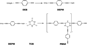
All synthetic reactions described below were carried out in a nitrogen atmosphere using Schlenk techniques. The B,B′,B′′-trichloroborazine (TCB) was prepared by allowing BCl3 to react with NH4Cl in toluene at 110 °C and purified by sublimation. The PBSZ resin was obtained according to the following procedure. EtMgBr (7.99 g, 0.06 mol) in 60 mL THF was added in a 250 mL four-necked flask equipped with a condenser, thermometer, mechanical agitation, and funnel. DEB (3.78 g, 0.03 mol) in 30 mL THF was dropped into EtMgBr solution and reacted at 70 °C for 2 h to synthesis diethynylphenyl-magnesium bromide (DEPM) as shown in Scheme 1. Then cooling the solution to 0 °C, TCB (1.84 g, 0.01 mol) in 70 mL toluene was dropwise added. After that, the mixture was allowed to heat up to 50 °C and stirring for an additional 4 h.31 The solution was cooled to room temperature and dioxane was added to the solution at last until no more precipitation was produced and then standing for 6 h. Subsequently, the suspension was centrifuged, then PBSZ resin was obtained by removing the solvent from the clear superstratum solution by rotary evaporation. Anal.: NMR (CDCl3): (1H, ppm) = 7.20–7.80 (m, Ar), 3.11 (s, –C![[triple bond, length as m-dash]](https://www.rsc.org/images/entities/char_e002.gif) CH), 5.60 (brs, –NH).
CH), 5.60 (brs, –NH).
2.3 Preparation of B3N3 doped activated carbons (B,N-ACs)
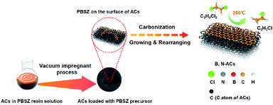
B,N-ACs were prepared by an incipient wetness vacuum impregnation technique using ACs and PBSZ resin solution shown in Scheme 2. The PBSZ resin was configured to 11 wt%, 13 wt%, 15 wt% and 17 wt% using THF solvent, respectively. PBSZ resin solution with a certain concentration was added quantitatively into 5 g ACs powder. Having been solvent extraction for 2 h and desiccated at 120 °C for 12 h, the dried PBSZ@ACs was calcined in a tubular furnace at 700 °C for 2 h under N2 atmosphere with a heating rate of 2.6 °C min−1. The PBSZ resin solution loading changed according to the mass ratio with constant ACs. The obtained B,N-ACs samples were labelled as shown in Table 1.| Samples | Concentration of PBSZ solution | Mass ratio with ACs |
|---|---|---|
| PBSZ–AC-1# | 11 wt% | 1![[thin space (1/6-em)]](https://www.rsc.org/images/entities/char_2009.gif) : :![[thin space (1/6-em)]](https://www.rsc.org/images/entities/char_2009.gif) 1 1 |
| PBSZ–AC-1* | 13 wt% | 1![[thin space (1/6-em)]](https://www.rsc.org/images/entities/char_2009.gif) : :![[thin space (1/6-em)]](https://www.rsc.org/images/entities/char_2009.gif) 1 1 |
| PBSZ–AC-1 | 15 wt% | 1![[thin space (1/6-em)]](https://www.rsc.org/images/entities/char_2009.gif) : :![[thin space (1/6-em)]](https://www.rsc.org/images/entities/char_2009.gif) 1 1 |
| PBSZ–AC-1′ | 17 wt% | 1![[thin space (1/6-em)]](https://www.rsc.org/images/entities/char_2009.gif) : :![[thin space (1/6-em)]](https://www.rsc.org/images/entities/char_2009.gif) 1 1 |
| PBSZ–AC-2 | 15 wt% | 2![[thin space (1/6-em)]](https://www.rsc.org/images/entities/char_2009.gif) : :![[thin space (1/6-em)]](https://www.rsc.org/images/entities/char_2009.gif) 1 1 |
| PBSZ–AC-3 | 15 wt% | 3![[thin space (1/6-em)]](https://www.rsc.org/images/entities/char_2009.gif) : :![[thin space (1/6-em)]](https://www.rsc.org/images/entities/char_2009.gif) 1 1 |
As a comparison, the ACs was calcined at 700 °C without the addition of PBSZ solution, and the obtained sample was denoted as AC.
2.4 Characterization and instrumentation
The structures of PBSZ were analysed using Fourier transform infrared spectroscopy (Nicolet-6700, Thermo Fisher Scientific Company) and 1H NMR spectroscopy (Bruker Avance 400). Morphological features characterization of the sample was performed using a high-resolution transmission electron microscope (HR-TEM, JEM-2100, JEOL Company, USA) and field emission scanning electron microscope (FE-SEM, S-4800, Hitachi Company, Japan). The XPS spectra were performed on X-ray photoelectron spectroscopy (EscaLab 250Xi, Thermo Fisher Scientific Company, USA). The X-ray diffraction (XRD) patterns were determined by the Bruker D8 Advance X-ray powder diffraction instrument with 2θ between 5° to 80°. Thermogravimetric analysis (TGA) was conducted with a TGA/DTA system (SDT Q600, TA Company, USA) at room temperature to 900 °C with the air flow of 10 °C min−1 in air atmosphere. Raman spectra were acquired using a micro-Raman spectroscopy system (inVia reflex, Renishaw Company, US, with excitation energy of 2.41 eV, 514 nm). Brunauer–Emmett–Teller (BET) surface area data were collected by obtaining nitrogen adsorption-desorption isotherms at 77 K using a Micromeritics ASAP 2020 analyzer.2.5 Catalytic activity evaluation
The catalytic performance of B,N-ACs and AC evaluation was performed in a fixed bed microreactor (i.d. = 6 mm). The temperature of the reactor was regulated using a temperature controller (Y-Feng, Shanghai, China). The 1,2-DCE flow rate was regulated using a 2ZB-1L10 piston pump (Weixin, Beijing, China). Before each of the reaction, the reactor was cleaned with nitrogen to remove moisture and air in the reaction system until the microreactor was heated to 250 °C. Afterward, liquid 1,2-DCE was fed into a vaporizing chamber with liquid hourly space velocity (LHSV) of 0.67 h−1 by a microinjection pump at a rate of 1 mL h−1. The effluent of the reactor was condensed to separate the unreacted 1,2-DCE and then passed into an absorption bottle containing water to remove HCl, followed by the composition analysis using a gas chromatograph (Shimadzu GC-2014) with a hydrogen flame ionization detector (FID).The conversion of 1,2-DCE (X) and the selectivity to VCM (S) as the criteria of catalytic performance were defined as the following equations, respectively:
| S = φ × 100% |
3. Results and discussion
3.1 Synthesis of the B,N-ACs
The PBSZ resin solution was prepared through the condensation reaction of TCB and DEPM, its structure was confirmed by the FTIR and 1H NMR as shown in Fig. S1.† The PBSZ solution was used as a precursor to impregnate ACs, which could supply the boron and nitrogen source simultaneously. The hybridization of atoms in the PBSZ resin, sp2 for boron in B3N3, sp2 for carbon in the benzene ring, and sp for carbon in the acetenyl group, enabled the 2D structure of the PBSZ. Among all kinds of the PBSZ solution concentration, when the concentration was lower than 13 wt%, it can be obviously found that the resin cannot be completely impregnated with the pore surface of the ACs from the catalytic performance as shown in Fig. S2† because the resin content was too low, the impregnating effect became worse. And when the concentration was higher than 15 wt%, the viscosity became higher. It was obvious that the PBSZ solution was difficult to uniformly impregnate on the pore surface of activated carbons, which also reduced the impregnating effect. This also can be demonstrated by the catalytic performance shown in Fig. S2.† Because of the poor impregnating effect, the performance of PBSZ–AC-1# and PBSZ–AC-1′ was far lower than that of PBSZ–AC-1* and PBSZ–AC-1. Therefore, the concentration limit of PBSZ solution has a great influence on the final catalytic performance.In the synthesis process of B,N-ACs, porous activated carbons with large specific surface area as the support and base planar which can enhance the contact area for the formation of active sites on the surface and 2D growth of PBSZ polymer, respectively. At the initial phase, PBSZ resin was firstly adsorbed on the surface of activated carbons under the action of negative pressure. Then, PBSZ resin began to grow up through the Diels–Alder reaction, coupling reaction and cycloaddition reaction based on the carbon–carbon triple bond on the surface of activated carbons during carbonization at 700 °C and formed a new molecular layer containing boron and nitrogen on the surface of activated carbons as shown in Scheme 2. 700 °C was beneficial to the growth of PBSZ on the one hand, and can also keep the high specific surface area of activated carbon as far as possible on the other hand.31 (In order to observe the growth thickness of the PBSZ molecular layer, the PBSZ precursor was carbonized at 700 °C, and the result was shown in Fig. S3,† which was about 2.8 nm.)
3.2 Characterization of the B,N-ACs
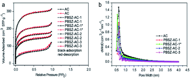 | ||
| Fig. 1 (a) N2 adsorption–desorption isotherms of the B,N-ACs catalysts; (b) the corresponding pore size distributions (PSD) on the surface of the B,N-ACs catalysts. | ||
| Sample | AC/PBSZ | SBETa (m2 g−1) | Vb (cm3 g−1) | N 1s contentc (atom%) | B 1s contentc (atom%) | ||||
|---|---|---|---|---|---|---|---|---|---|
| Fresh | Used | Fresh | Used | Fresh | Used | Fresh | Used | ||
| a SBET: special surface area.b V: total pore volume.c Surface element content determined by XPS. | |||||||||
| AC | 1![[thin space (1/6-em)]](https://www.rsc.org/images/entities/char_2009.gif) : :![[thin space (1/6-em)]](https://www.rsc.org/images/entities/char_2009.gif) 0 0 |
965 | 920 | 0.49 | 0.47 | — | — | — | — |
| PBSZ–AC-1* | 1![[thin space (1/6-em)]](https://www.rsc.org/images/entities/char_2009.gif) : :![[thin space (1/6-em)]](https://www.rsc.org/images/entities/char_2009.gif) 1 1 |
678 | 542 | 0.36 | 0.28 | 1.46 | 0.97 | 0.33 | 0.32 |
| PBSZ–AC-1 | 1![[thin space (1/6-em)]](https://www.rsc.org/images/entities/char_2009.gif) : :![[thin space (1/6-em)]](https://www.rsc.org/images/entities/char_2009.gif) 1 1 |
531 | 524 | 0.29 | 0.28 | 1.23 | 1.22 | 0.41 | 0.28 |
| PBSZ–AC-2 | 1![[thin space (1/6-em)]](https://www.rsc.org/images/entities/char_2009.gif) : :![[thin space (1/6-em)]](https://www.rsc.org/images/entities/char_2009.gif) 2 2 |
441 | 399 | 0.26 | 0.24 | 1.62 | 1.01 | 0.40 | 0.38 |
| PBSZ–AC-3 | 1![[thin space (1/6-em)]](https://www.rsc.org/images/entities/char_2009.gif) : :![[thin space (1/6-em)]](https://www.rsc.org/images/entities/char_2009.gif) 3 3 |
199 | 47 | 0.19 | 0.09 | 1.45 | 0.97 | 0.54 | 0.38 |
According to the investigation of the textural properties of the catalyst, the formation process of the B,N-ACs catalyst was deduced as follows. First, the PBSZ resin was uniformly absorbed on the surface of ACs. Then the resin started to grow up to a certain molecular weight during carbonation process at 700 °C on the surface of ACs. Next, the boron and nitrogen co-doped ACs with the coexistence of micropores and mesopores was formed. As shown in Table 2, a certain dosage (ratio of PBSZ/ACs) and concentration of PBSZ resin solution were very critical to control the special surface area and total pore volume of the catalyst which decided the amount and distribution of the active sites of the catalyst. It can be seen that with the increase of dosage of PBSZ, the specific surface area and total pore volume were decreased, especially PBSZ–AC-3, mainly due to the mesopores formed by the deposition of the polymer as discussed above. In addition, the PBSZ–AC-1* exhibited higher special surface area and N atoms content than the PBSZ–AC-1, due to the lower concentration of the PBSZ resin solution on ACs. The very thin film of PBSZ polymer formed on the surface of ACs, which produced catalytic active structure, but not seriously blocked the micropores of ACs.
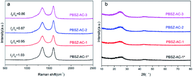
Fig. 3b showed the XRD patterns of the fresh catalysts. Two distinct diffraction planes with peak positions at 25° and 43° were detected in all catalysts, which correspond to the (002) and (101) diffraction planes of graphitic carbon.46 The peaks of magnesium salt were not detected in the material, indicating the magnesium salt have been disappeared by acid pickling, and the catalytic performance had nothing to do with the metal.
3.3 Catalytic performance of the B,N-ACs
To investigate the influence of N and B on the catalytic performance of dehydrochlorination of 1,2-DCE, the B,N-ACs and AC were evaluated, respectively, as shown in Fig. 5. To reduce the influence of errors, the investigation of the catalytic performance started when the reaction reached the restively stable state. AC showed very low catalytic performance of the dehydrochlorination, with the conversion of 1,2-DCE only 19.8%, and the selectivity of VCM ∼92.9% at 250 °C, due to almost no active sites on AC. Compared with AC, the B,N-ACs all exhibited excellent catalytic performance, with the 1,2-DCE conversion 61.7%, 71.4%, 75.2% and 92.0%, and the selectivity of VCM 99.0%, 99.5%, 99.7% and 99.9% over PBSZ–AC-3, PBSZ–AC-2, PBSZ–AC-1 and PBSZ–AC-1*, respectively.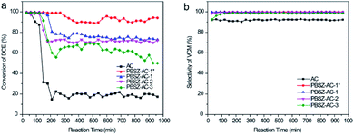 | ||
| Fig. 5 (a) The conversion of 1,2-DCE over the B,N-ACs catalysts; (b) the selectivity of VCM over the B,N-ACs catalysts. Reaction conditions: temperature = 250 °C, 0.1 MPa, LHSV (1,2-DCE) = 0.67 h−1. | ||
The result indicated that the B, N-dopant could greatly increase the catalytic activity of ACs for 1,2-DCE dehydrochlorination. In addition, it can be found that PBSZ–AC-1* has the best catalytic performance, mainly because it has the highest specific surface area and pore volume, giving it the highest defect density, which is also consistent with the Raman results. The catalytic performance of other catalysts also confirmed to this statement.
3.4 The study on active sites of the B,N-ACs
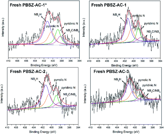
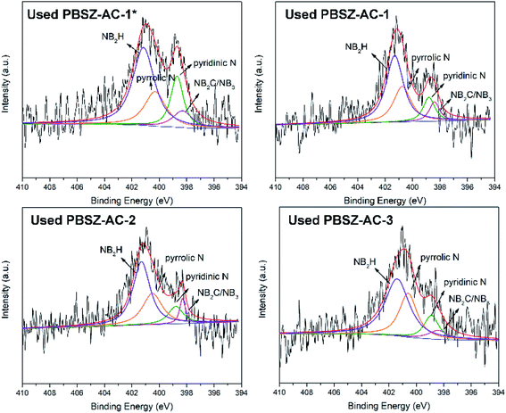
To study the active sites and mechanism of the dehydrochlorination, the high-resolution N 1s spectrum of the fresh and used B,N-ACs catalysts were performed by XPS analysis. As shown in Fig. 4 and Table 3. As shown in Table 3, PBSZ–AC-1* had the highest content of the internal B3N3 and pyridinic-N, while the content of the pyrrolic-N and exterior B3N3 was the lowest among all the catalysts. The catalysts soaked with a higher PBSZ resin solution concentration was just the opposite. With the increase of dosage of PBSZ, the content of internal B3N3 and pyridinic-N decreased, while the content of pyrrolic-N and exterior B3N3 increased. With the increase of PBSZ resin solution concentration and dosage, the PBSZ formed a much thicker film by polymerization on the surface of ACs. Compared with the thin film, the chemical states of N atom were difficultly to transform in the thicker polymer film at the carbonization condition. So, it is very crucial to control the dosage of the PBSZ to increase the distribution of N and B atoms and the content of the internal B3N3 and pyridinic-N in the catalysts. As can be seen from the catalytic performance of the dehydrochlorination of 1,2-DCE over the B,N-ACs catalysts, PBSZ–AC-1* exhibited the highest conversion of 1,2-DCE and selectivity to VCM, and with the increase of PBSZ solution concentration and dosage, the catalytic performance decreased gradually. The study showed that the change rule of the catalytic performance over the B,N-ACs catalysts was consistent with that of the N and B chemical states. As shown in Table 3, line 7, with the increase of the dosage and concentration of the PBSZ, the total content of the internal B3N3 and pyridinic-N decreased gradually, but the content of the pyrrolic-N and the exterior B3N3 increased. Therefore, it was concluded that the internal B3N3 and pyridinic-N were the active sites in the B,N-ACs catalysts, which play crucial roles in the dehydrochlorination of 1,2-DCE reaction. In order to further verify this result, XPS was employed on the used catalyst and the high-resolution regional spectra of N 1s as shown in Fig. 6. There are four obvious peaks on the used catalyst like the fresh catalyst. As shown in Table 3, corresponding to each fresh catalyst, the content of the internal B3N3 and pyridinic-N in used catalysts decreased, and the content of pyrrolic-N and the exterior B3N3 increased, which further showed that compared with pyrrolic-N and the exterior B3N3, the internal B3N3 and pyridinic-N were more likely active sites of the dehydrochlorination of 1,2-DCE reaction. The pyridinic-N and the internal B3N3 species were partly covered by the coke-deposition in the reaction. Therefore, the contents were relatively decreased.| Catalysts | NIa (%) | NPb (%) | NPyrc (%) | NEd (%) | NI + NP (%) | NPyr + NE (%) |
|---|---|---|---|---|---|---|
| a Structure of NB2C or the NB3 in the interior site (the internal B3N3).b Pyridinic N.c Pyrrolic N.d The N of amide groups (NB2H) in the B3N3 (the external B3N3). | ||||||
| PBSZ–AC-1* | 13.50 | 20.90 | 22.00 | 43.60 | 34.40 | 65.60 |
| PBSZ–AC-1 | 9.84 | 19.12 | 24.59 | 46.45 | 28.96 | 71.04 |
| PBSZ–AC-2 | 8.33 | 16.67 | 25.00 | 50.00 | 25.00 | 75.00 |
| PBSZ–AC-3 | 7.50 | 13.33 | 27.50 | 51.67 | 20.83 | 79.17 |
| Used PBSZ–AC-1* | 9.40 | 18.70 | 22.60 | 49.30 | 28.10 | 71.90 |
| Used PBSZ–AC-1 | 8.90 | 12.33 | 27.40 | 51.37 | 21.23 | 78.77 |
| Used PBSZ–AC-2 | 6.90 | 12.41 | 28.98 | 51.72 | 19.31 | 80.69 |
| Used PBSZ–AC-3 | 6.45 | 12.90 | 29.03 | 51.62 | 19.35 | 80.65 |
3.5 The study on deactivation of the B,N-ACs
To analyse the coke deposition of catalysts and clarify the reason for the deactivation of the catalysts, TGA was performed to demonstrate the analysis results as shown in Fig. 7. Below 100 °C, the slight weight loss of the catalyst was due to the moisture evaporation and other small molecules which were adsorbed on the catalysts. In the temperature range of 100–500 °C, the weight loss of the used catalysts was higher than that of the fresh catalyst. The difference value of weight loss between the fresh and used catalysts caused by the coke deposit and residual of reaction mass on the catalyst surface, indicating that the side reaction occurred on the catalysts surface during the dehydrochlorination of 1,2-DCE. While over 500 °C, the mass loss of the catalysts was due to the burning of the ACs support in an air atmosphere. The TGA results indicated that the coke deposition may be the main reason for the deactivation of the catalysts. In addition, the amount of the coke deposition of PBSZ–AC-1*, PBSZ–AC-1, PBSZ–AC-2 and PBSZ–AC-3 was 3.87%, 2.99%, 2.43% and 1.31%, respectively, during the catalytic reaction. The results indicated that coke deposition gradually increased with the decreasing of the dosage and PBSZ resin solution concentration. Therefore, with a suitable content of PBSZ precursor, the B,N-ACs catalysts had more potential to adsorb and activate the 1,2-DCE in the dehydrochlorination, and at the same time, the much more micropores on the catalyst caused the side reaction, due to the long dwell time.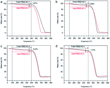 | ||
| Fig. 7 Thermogravimetric analysis (TGA) curves recorded in air atmosphere of fresh and used catalysts, (a) PBSZ–AC-1*, (b) PBSZ–AC-1, (c) PBSZ–AC-2, (d) PBSZ–AC-3. | ||
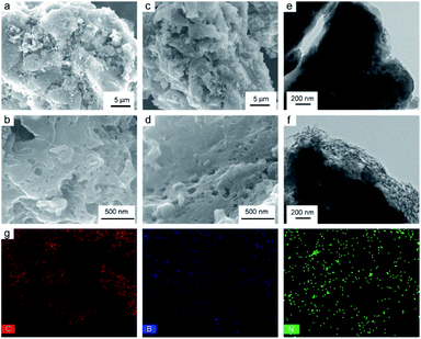
To further verify the deactivation of the catalyst due to coke deposition, N2 adsorption–desorption isotherms analysis and SEM were performed on the used catalysts, as shown in Fig. S8,† 2c, d and Table 2. The surface area and total pore volume of used catalysts were lower than those of the corresponding fresh (in Table 2), suggesting that the pores of catalysts were partially blocked during the 1,2-DCE dehydrochlorination reaction and indicating that the reason for inactivation should be acetylene polymerization resulting in carbon deposition and pore blocking. It also can be seen that the surface of used catalyst was partly covered after the catalytic reaction, with the densification of pores on the used catalyst because of the coke deposition, as shown in Fig. 2b and d by SEM. Therefore, it can be explained that the main reason for catalyst deactivation was that coke deposition occurred in the dehydrochlorination of 1,2-DCE, which blocks the active sites of the catalyst. Whereas it can be found in Fig. 2a and c, the overall morphology of fresh and used catalysts remained unchanged after the catalytic reaction, indicating that the catalysts had excellent structural stability.
4. Conclusion
Boron and nitrogen co-doped activated carbons in the form of B3N3 catalysts was prepared using B3N3-containing arylacetylene resin for the dehydrochlorination of 1,2-DCE to produce VCM. Compared to pristine AC, PBSZ–AC-1* with 1,2-DCE conversion about 92.0% and selective to vinyl chloride 99.9% at 250 °C showed significantly improved catalytic performance. Moreover, the good performance was mainly due to the synergistic effects of boron and nitrogen co-doping. From the comprehensive consideration of the XPS results and the catalytic activity data, it could be realized and further verified that pyridinic-N and the internal B3N3 were the active sites for the dehydrochlorination of 1,2-DCE. The new metal-free and environmentally friendly boron and nitrogen co-doped catalyst prepared in this work opened up the future potential study in the green and sustainable industrial process preparation of vinyl chloride by using boron and nitrogen co-doped carbon catalysts.Conflicts of interest
There are no conflicts to declare.Acknowledgements
This work is supported by the National Natural Science Foundation of China (90816021 and 20874028), the Fundamental Research Funds for the Central University (5032104918013, 5032104917001). The Key Laboratory of Specially Functional Polymeric Materials and Related Technology of Ministry of Education, East China University of Science & Technology was responsible for the synthesis and characterization of the samples, and Green Chemical Engineering Research Centre, Shanghai Advanced Research Institute, Chinese Academy of Sciences, Shanghai Green Chemical Engineering Research Centre, Shanghai Institute of Organic Chemistry, Chinese Academy of Sciences was responsible for the catalytic activity evaluation of the samples.References
- W. Zhao, M. X. Sun, H. Y. Zhang, Y. Z. Dong, X. Y. Li, W. Li and J. L. Zhang, RSC Adv., 2015, 5, 104071–104078 RSC.
- C. Sotowa, Y. Watanabe, S. Yatsunami, Y. Korai and I. Mochida, Appl. Catal., A, 1999, 180, 317–323 CrossRef CAS.
- T. Boudewijns, M. Piccinini, P. Degraeve, A. Liebens and D. De Vos, ACS Catal., 2015, 5, 4043–4047 CrossRef CAS.
- S. Bai, Q. Dai, X. Chu and X. Wang, RSC Adv., 2016, 6, 52564–52574 RSC.
- N. V. Testova, A. S. Shalygin, T. S. Glazneva, E. A. Paukshtis and V. N. Parmon, Catal. Commun., 2015, 67, 95–97 CrossRef CAS.
- A. Śrębowata, R. Baran, I. I. Kamińska, T. Onfroy, J.-M. Krafft and S. Dzwigaj, Catal. Today, 2015, 251, 73–80 CrossRef.
- A. G. Borsa, A. M. Herring, J. T. McKinnon, R. L. McCormick and G. H. Ko, Ind. Eng. Chem. Res., 2001, 40, 2428–2436 CrossRef CAS.
- A. Shalygin, L. M. Koval, L. Malysheva, N. S. Kotsarenko and E. Paukshtis, Chem. Sustainable Dev., 2009, 17, 417–422 Search PubMed.
- K. Okamoto, N. Tanaka, K. Adachi and H. Shingu, Bull. Chem. Soc. Jpn., 1966, 39, 1522–1524 CrossRef CAS.
- J. J. Prinsloo, P. C. Van Berge and J. Zlotnick, J. Catal., 1974, 32, 466–469 CrossRef CAS.
- C. Sotowa, Y. Watanabe, S. Yatsunami, Y. Korai and I. Mochida, Appl. Catal., A, 1999, 180, 317–323 CrossRef CAS.
- X. Sun, Y. Qin, Q. Li, X. Liu, Z. Liu, L. Song and Z. Sun, Catal. Sci. Technol., 2018, 8, 5334–5343 RSC.
- D. R. Dreyer and C. W. Bielawski, Chem. Sci., 2011, 2, 1233–1240 RSC.
- D. S. Su, S. Perathoner and G. Centi, Chem. Rev., 2013, 113, 5782–5816 CrossRef CAS.
- K. Zhou, B. Li, Q. Zhang, J.-Q. Huang, G.-L. Tian, J.-C. Jia, M.-Q. Zhao, G.-H. Luo, D. S. Su and F. Wei, ChemSusChem, 2014, 7, 723–728 CrossRef CAS.
- W. Chen, L. Xu, Y. H. Tian, H. A. Li and K. Wang, Carbon, 2018, 137, 458–466 CrossRef CAS.
- J. J. Wu, M. T. F. Rodrigues, R. Vajtai and P. M. Ajayan, Adv. Mater., 2016, 28, 6239–6246 CrossRef CAS.
- N. Chen, X. K. Huang and L. T. Qu, Phys. Chem. Chem. Phys., 2015, 17, 32077–32098 RSC.
- M. Peyravi, Polym. Adv. Technol., 2018, 29, 319–328 CrossRef CAS.
- C. Zhu, C. Kim, Y. Aoki and H. Habazaki, Adv. Mater. Interfaces, 2017, 4, 1700583 CrossRef.
- S. Ullah, P. A. Denis and F. Sato, ChemPhysChem, 2017, 18, 1864–1873 CrossRef CAS.
- J. Xu, X. Zhao, A. Wang and T. Zhang, Carbon, 2014, 80, 610–616 CrossRef CAS.
- Y.-N. Sun, M.-L. Zhang, L. Zhao, Z.-Y. Sui, Z.-Y. Sun and B.-H. Han, Adv. Mater. Interfaces, 2019, 6, 1900592 CrossRef.
- P. A. Denis and C. Pereyra Huelmo, Carbon, 2015, 87, 106–115 CrossRef CAS.
- Y. Gong, H. Fei, X. Zou, W. Zhou, S. Yang, G. Ye, Z. Liu, Z. Peng, J. Lou, R. Vajtai, B. I. Yakobson, J. M. Tour and P. M. Ajayan, Chem. Mater., 2015, 27, 1181–1186 CrossRef CAS.
- Y. Guo, Z. Zeng, Y. Liu, Z. Huang, Y. Cui and J. Yang, J. Mater. Chem. A, 2018, 6, 4055–4067 RSC.
- Y. Zhang, J. Zhang and D. S. Su, ChemSusChem, 2014, 7, 1240–1250 CrossRef CAS.
- G. Wang, M. Zhang, D. Chen, Q. Guo, X. Feng, T. Niu, X. Liu, A. Li, J. Lai, D. Sun, Z. Liao, Y. Wang, P. K. Chu, G. Ding, X. Xie, Z. Di and X. Wang, Nat. Commun., 2018, 9, 5168 CrossRef.
- T. V. Vineesh, M. A. Nazrulla, S. Krishnamoorthy, T. N. Narayanan and S. Alwarappan, Appl. Mater. Today, 2015, 1, 74–79 CrossRef.
- Y. Zheng, Y. Jiao, L. Ge, M. Jaroniec and S. Z. Qiao, Angew. Chem., Int. Ed., 2013, 52, 3110–3116 CrossRef CAS.
- C. Chen, K. Guo, Y. Zhu, F. Wang, W. Zhang and H. Qi, ACS Appl. Mater. Interfaces, 2019, 11, 33245–33253 CrossRef CAS.
- L. Dai, Y. Xue, L. Qu, H.-J. Choi and J.-B. Baek, Chem. Rev., 2015, 115, 4823–4892 CrossRef CAS.
- S. Kattel, P. Atanassov and B. Kiefer, J. Mater. Chem. A, 2014, 2, 10273–10279 RSC.
- H. Wang, Q. Mu, K. Wang, R. A. Revia, C. Yen, X. Gu, B. Tian, J. Liu and M. Zhang, Appl. Mater. Today, 2019, 14, 108–117 CrossRef.
- D. Bonifazi, F. Fasano, M. M. Lorenzo-Garcia, D. Marinelli, H. Oubaha and J. Tasseroul, Chem. Commun., 2015, 51, 15222–15236 RSC.
- K. Guo, H. Qi, F. Wang and Y. Zhu, Mater. Sci. Eng., B, 2014, 186, 7–14 CrossRef CAS.
- M. Krieg, F. Reicherter, P. Haiss, M. Ströbele, K. Eichele, M. J. Treanor, R. Schaub and H. F. Bettinger, Angew. Chem., Int. Ed., 2015, 54, 8284–8286 CrossRef CAS.
- C. Sánchez-Sánchez, S. Brüller, H. Sachdev, K. Müllen, M. Krieg, H. F. Bettinger, A. Nicolaï, V. Meunier, L. Talirz, R. Fasel and P. Ruffieux, ACS Nano, 2015, 9, 9228–9235 CrossRef.
- S. Sanyal, A. K. Manna and S. K. Pati, J. Mater. Chem. C, 2014, 2, 2918–2928 RSC.
- S. Saha, M. Jana, P. Khanra, P. Samanta, H. Koo, N. C. Murmu and T. Kuila, ACS Appl. Mater. Interfaces, 2015, 7, 14211–14222 CrossRef CAS.
- Y. Kang, Z. Chu, D. Zhang, G. Li, Z. Jiang, H. Cheng and X. Li, Carbon, 2013, 61, 200–208 CrossRef CAS.
- Z. Shen, H. Zhao, Y. Liu, Z. Kan, P. Xing, J. Zhong and B. Jiang, React. Chem. Eng., 2018, 3, 34–40 RSC.
- H. Zhao, S. Chen, M. Guo, D. Zhou, Z. Shen, W. Wang, B. Feng and B. Jiang, ACS Omega, 2019, 4, 2081–2089 CrossRef CAS.
- C. Zhang, L. Kang, M. Zhu and B. Dai, RSC Adv., 2015, 5, 7461–7468 RSC.
- N. Zydziak, B. Yameen and C. Barner-Kowollik, Polym. Chem., 2013, 4, 4072–4086 RSC.
- X. Li, J. Zhang and W. Li, J. Ind. Eng. Chem., 2016, 44, 146–154 CrossRef CAS.
- Y. Liu, S. Chen, X. Quan, H. Yu, H. Zhao, Y. Zhang and G. Chen, J. Phys. Chem. C, 2013, 117, 14992–14998 CrossRef CAS.
- D.-W. Lee, M.-H. Jin, D. Oh, S.-W. Lee and J.-S. Park, ACS Sustainable Chem. Eng., 2017, 5, 9935–9944 CrossRef CAS.
- P. Li, H. Li, X. Pan, K. Tie, T. Cui, M. Ding and X. Bao, ACS Catal., 2017, 7, 8572–8577 CrossRef CAS.
- W. Zhao, M. Zhu and B. Dai, Catal. Commun., 2017, 98, 22–25 CrossRef CAS.
Footnotes |
| † Electronic supplementary information (ESI) available. See DOI: 10.1039/d0ra10037d |
| ‡ These authors contributed equally. |
| This journal is © The Royal Society of Chemistry 2021 |

