 Open Access Article
Multi-scale microstructure high-strength titanium alloy lattice structure manufactured via selective laser melting
Xin Yang*a,
Wenjun Maa,
Wenping Gub,
Zhaoyang Zhanga,
Ben Wanga,
Yan Wangc and
Shifeng Liu*c
aCollege of Materials Science and Engineering, Xi'an University of Technology, Xi'an 710048, China. E-mail: yangx@xaut.edu.cn
bElectronic Science and Technology, Chang'an University, Xi'an 710061, China
cSchool of Metallurgical and Engineering, Xi'an University of Architecture & Technology, Xi'an 710055, China. E-mail: Liushifeng66@xauat.edu.cn
First published on 29th June 2021
Abstract
The tensile performance of Ti6Al4V alloy lattice structure was investigated. Firstly, a face center cubic unit cell with vertical struts (F2CCZ) lattice structure was designed. Then, the structures were fabricated by selective laser melting (SLM) with different aspect ratios. Subsequently, the SLM-ed alloys were subjected to double solution-aging to homogenize the microstructure and release residual stress. It is shown that there is only acicular α′ martensite with high dislocation density in the SLM-ed alloy, while the heat-treated alloy has α and β phases (there are multi-scale α laths and nano-scale β particles), and the orientation relationship between the two phases is: [113]β//[1210]α. The tensile strength of the HT-ed alloys presents a significant increase from 140 ± 18 MPa in the SLM-ed state to 229 ± 5.1 MPa with an aspect ratio of 4. It indicates that the special heat treatment regime can not only homogenize the microstructure of the SLM-ed alloy, but also improve the tensile strength.
1. Introduction
Titanium alloy has advantages of high specific strength, low elastic modulus, high energy absorption and strong corrosion resistance. It has been widely used in the field of medical implantation especially for its good biocompatibility, among which Ti6Al4V (Ti64) alloy accounts for more than 50%.1 However, the elastic modulus of the bulk Ti64 alloy ranges from 90 GPa to 110 GPa2 which is much higher than that of cortical bones such as the femur and tibia (0–35 GPa),3 and such large elastic modulus mismatch between the implant and the surrounding bone tissue results in stress shielding around the implant, leading to failure of the regeneration of bone cells.4 Therefore, it is of great importance to reduce modulus mismatch in the biomedical field.5 The Ti64 lattice structure has a low elastic modulus (0–40 GPa) that matches well with that of the femur and tibia.6 Additionally, the space between the structures promotes the integration of bone cells making it the preferred choice for medical implantation.7 In recent years, selective laser melting (SLM) technology is capable of realizing complex lattice patient-specific structures from medical grade metallic powder materials.8At present, the research on SLM-Ti64 lattice structure mainly focuses on the preparation of Ti64 lattice structure and its compression performance. M. Mazur et al.9 took the Ti64 spherical powder with an average particle size D50 of 40 μm as the raw material, and studied the manufacturability of the Ti64 alloy lattice strut using SLM technology. The results show that the minimum manufacturing strut diameter is 0.2 mm, and the minimum inclination angle is 20°. S. Gangireddy et al.10 used Ti64 spherical powder with a particle size distribution of 15–45 μm as the raw material, and prepared the octahedral lattice structure using SLM technology. The results show that total energy absorption and compressive strength are positively correlated with relative density. When the relative density is 0.354, the compressive strength is 75 MPa. Other studies also showed that the Ti64 lattice structure prepared by SLM usually has higher compressive strength, lower elastic modulus and good biocompatibility than traditional structure.11
Clinical results indicate that most cortical bone fractures are caused by tensile or bending strains.12 Although only a limited number of studies have so far been conducted on the tensile properties of the SLM-ed Ti64 lattice structure, it is however possible to come up with a few. Among them, S. Raghavendra13 et al. used SLM technology to prepare a random porous lattice structure of Ti64 alloy. When the relative density is equivalent to that of cortical bone, the tensile strength can reach 250 MPa, but its disordered microstructure is more prone to failure under tensile load than under compression. S. M. Ahmadi et al.14 treated the diamond Ti64 lattice structure prepared by SLM technology at 1050 °C for 2 hours. The results show that the microstructure changes from fine needle-shaped α′ martensite to α + β mixed structure after heat treatment as previously observed,15 the α + β interface is an effective barrier for crack propagation. The growing α-laths make its tensile strength drop sharply. In order to be used safely on the human body for a long time, it is urgent to obtain high tensile strength while improving its microstructure. In this study, F2CCZ (face-centered cubic unit cell with vertical struts) structure type tensile parts were prepared by SLM. Double solid solution aging heat treatment is used to homogenize the alloy microstructure while obtaining a controllable mixed structure, improving the microstructure while obtaining high tensile strength. On this basis, the tensile performance of the samples both with and without heat treatment was studied and discussed.
2. Experimental
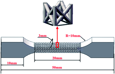
A face center cubic unit cell with vertical struts (F2CCZ) lattice structure was designed by Solid Works 2013. The size of the unit cell was magnified to 1 mm × 1 mm × 1 mm. The number of unit cells was set at 3 × 3 × 20. Struts diameters of lattice structures were set from 0.2 mm to 0.33 mm. It is named F-X according to its length–diameter ratio. For example, a unit cell with a length of 1 mm and a diameter of 0.2 mm is named F-5, and the specific strut dimensions are shown in Table 1. The designed tensile sample with lattice structure and a unit cell are shown in Fig. 1.| Number | l/mm | d/mm | l/d |
|---|---|---|---|
| F-5 | 1 | 0.2 | 5 |
| F-4 | 1 | 0.25 | 4 |
| F-3 | 1 | 0.33 | 3 |
The lattice structures were manufactured by a selective laser melting equipment (Mlab cusing R, Concept Laser, Germany). The parameters for manufacturing samples are shown in Table 2. Argon atmosphere was used to prevent oxidation of Ti64 alloys during melting. The Ti64 raw powder morphology and particle size distribution are shown in Fig. 2a and b. The scanning strategy is a 45° checkerboard and the scanning direction is rotated by 90° after each layer, as shown in Fig. 2c. The powder exhibits high sphericity and a small amount of satellite powder. The particle size is 15–53 μm, of which D50 is 45 μm. Subsequently, a double solution-aging heat treatment process was carried out: firstly, the sample was kept at 1030 °C for 120 min, then at 1000 °C for 60 min, and finally at 600 °C for 360 min. All alloys were air-cooled.
| Item | Parameter |
|---|---|
| Laser power | 100 W |
| Scanning speed | 600 mm s−1 |
| Layer thickness | 25 μm |
| Scanning space | 80 μm |
 | ||
| Fig. 2 (a) Morphology of Ti64 raw powder, (b) particle size distribution and (c) checkerboard scan strategy. | ||
The samples were sanded with different mesh sandpaper and polished with 0.5 μm SiO2 suspension. After polishing, the samples were etched with a mixed solution (92 ml H2O + 6 ml HNO3 + 2 ml HF) for 90 s. The phase compositions of the raw powder and the shaped sample were analyzed by an XRD X-ray diffractometer (XRD-7000, Japan), and the XRD test was performed using a Cu target in a step of 0.02°. The surface morphology of the lattice structure was observed by a laser scanning confocal microscope (LEXT OLS4000, Japan). Samples for TEM (Themis Z, America) observations were prepared by electrolytic polishing using a mixture of 5% perchloric acid, 25% normal butanol and 70% methanol at 243 K and 28 V. The fracture morphology and microstructure were observed with scanning electron microscopy (Gemini SEM 300, Germany).
Tensile tests were carried out on the specimens in a universal testing machine (INSTRON 5982, United States) with a 100 kN force cell. Tensile tests were conducted at a constant displacement (0.2 mm min−1). The stress is calculated by the following formula according to ISO 13314:2011, Sdesign represents the design area perpendicular to the loading direction.
 | (1) |
Since the prepared lattice structure has a regular pore structure, the density of the porous tensile specimen can be calculated by the following formula:
 | (2) |
 | (3) |
3. Results
3.1. Profiles of lattice structures
The profiles of lattice structures with different aspect rations are presented in Fig. 3. Some hanging slags were found on the inclined struts of F2CCZ structures. This phenomenon is often observed in the lattice structures due to the force of gravity on the melting pools.16 The analysis of the strut diameters of lattice structures with different aspect ratios can be seen in Table 3. As the designed strut diameter increases from 0.2 mm to 0.33 mm, its actual dimensional accuracy improves. The diameter of inclined-strut is much larger than the design model, and the diameter of build direction-strut is close to the design model. The spatter particles and spherical particles on the surface of lattice structure influenced the dimensional accuracy.17 The path planning and spot compensation of laser also affect the shape of lattice structures.18 | ||
| Fig. 3 Profiles of lattice structure: (a) SLM-ed, (b) F-5-struts, (c) F-4-struts and (d) F-3-struts. | ||
| Number | Inclined-measure (mm) | Build direction-measure (mm) | Struts-design (mm) |
|---|---|---|---|
| F-5 | 0.31 ± 0.031 | 0.19 ± 0.024 | 0.2 |
| F-4 | 0.35 ± 0.022 | 0.27 ± 0.003 | 0.25 |
| F-3 | 0.36 ± 0.013 | 0.33 ± 0.005 | 0.33 |
3.2. XRD analyses
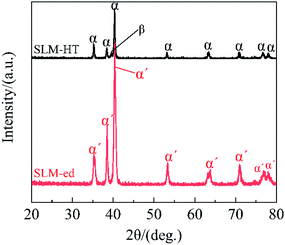
The XRD patterns of SLM-ed and HT-ed Ti64 alloys are shown in Fig. 4. XRD patterns of HT-ed contain a mixture of α phase and β phase. However, the XRD patterns of SLM-ed only contain α′ phase. When the cooling rate exceeds 410 °C s−1, complete α′ martensite will be produced, and this transformation is very common in the Ti64 alloy manufactured by SLM.19 Because the cooling speed is very fast (103−105 °C s−1) during the SLM processing, most of β structures transformed to the martensitic structures. Moreover, these peaks of HT-ed show higher intensity of α characteristic peaks than SLM-ed. It implies that the size of α phase grain grew up during the heat treatment. The quantitative analyses of XRD patterns are shown in Table 4. It shows that the sample contains 5.1% β phase after heat treatment, while the SLM-ed alloy has almost no β-phase. The similar results were found by Ahmadi et al.14 and Yuan et al.20 Different from the SLM-ed bulk Ti64 alloy, no β phase is observed in the SLM-ed lattice structure. This may be resulted from the faster cooling rate in the SLM-ed lattice material than in the SLM-ed bulk material.| SLM-ed | HT-ed | |
|---|---|---|
| α-Phase (%) | Close to 100 | 94.9 |
| β-Phase (%) | Close to 0 | 5.1 |
3.3. Microstructural observation
Microstructures of SLM-ed and HT-ed alloys are shown in Fig. 5. Fig. 5a and b shows the longitudinal section, with columnar grains parallel to the building direction. These elongated structures arose from the prior β columnar grains formed during the solidification stage of the liquid and were retained to room temperature.21 Moreover, the cooling rate in the SLM process is as high as 105 °C s−1.21 At this cooling rate, β phase will directly transform to α′ martensite phase with an acicular appearance, and the acicular α′ martensite was distributed within the columnar structure. The acicular α′ martensitic structure occupies most of the SLM-ed, which is different from the ASTM Grade 5 alloy (α + β) and the SLM bulk Ti64 alloy (α'+ β). Comparing SLM-ed with HT-ed (Fig. 5c and d), it is found that the α laths in HT-ed became coarser, which was also reported in ref. 22. The size of α lath increases with temperature. In addition, some nanosized particles are dispersedly distributed on the α laths. It was demonstrated that these nano-sized particles are the nano-sized β particles in the research.19 Some pores are observed in this topography, and these pores will affect the mechanical properties23 and corrosion performance.24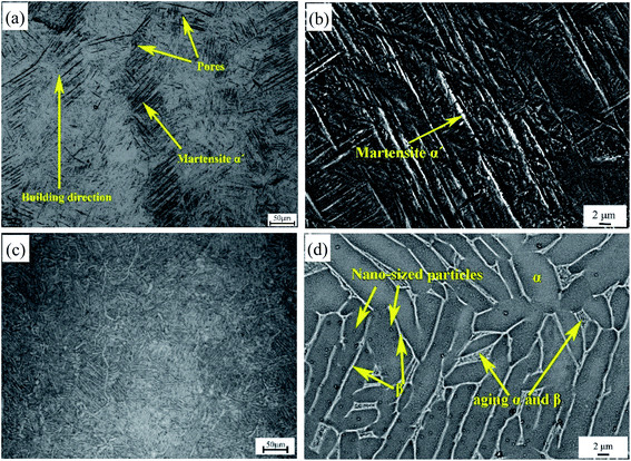 | ||
| Fig. 5 OM images (a) and (c) of SLM-ed and HT-ed, respectively, and the corresponding SEM images (b) and (d). | ||
Fig. 6a and b show the bright field images and corresponding selected area electron diffraction (SAED) patterns of SLM-ed alloy. It is seen that the SLM-ed alloy is mainly composed of α′ phase, which is caused by the non-diffusion phase transition with high cooling rate. There are high dislocation density and many crystal defects in the martensite grains, indicating that the stress relaxation in the transition from β to α′ phase is mainly realized by dislocation formation. No residual β-phase diffraction pattern was detected in the SLM-ed alloy, which is consistent with the XRD results. The similar result was observed by Wu et al.25
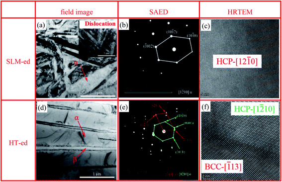 | ||
| Fig. 6 TEM bright field images (a and d) of SLM-ed and HT-ed, respectively, and the corresponding diffraction pattern (b and e), and HRTEM images (c and f). | ||
Fig. 6d and e show the bright field image and corresponding SAED patterns of the HT-ed alloy, in which the α and β phases are observed. When solid solution at high temperature, α phase transforms to β phase. Diffusion transition occurs during air cooling, and β phase forms α lamellar and remaining β phase. The similar result was found by Zhang et al.6 Different from the SLM-ed alloy, no α′ phase is observed in the HT-ed alloy. This resulted from the slower cooling rate in the HT-ed alloy than in the SLM-ed alloy. The orientation relationship between the β and α phases is presented by: [113]β//[1−210]α, as reported by Zhang et al.26 and Wan et al.27 The high-resolution TEM image presented the interface between a BCC and HCP structures (Fig. 6f), further confirmed the orientation relationship. According to the requirement for implants materials specified in ISO 20160, a homogeneous microstructure of high-density biomaterials is necessary to provide material integrity and stability.28 According to Fig. 5 and 6, the width of acicular martensite grains of the SLM-ed alloy is in the range of 30–450 nm. The heat treatment not only eliminates the high dislocation density of the SLM-ed alloys, but also obtains martensite laths with multi-level scales. The width of the primary α produced by the first solid solution is greater than 2 μm, the width of the secondary α produced by the second solid solution is in the range of 1–2 μm, and the width of α produced by the final aging is about 450 nm. N. Hrabe et al.29 showed that the width of α lath is directly related to its mechanical properties. The existence of multi-scale α-laths can obtain better comprehensive mechanical properties.
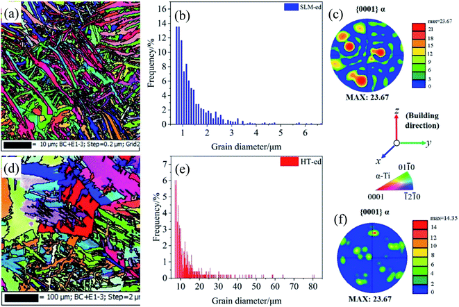
To further identify the effect of heat treatment on the SLM-ed Ti64 lattice structure microstructure, the samples with and without heat treatment were analyzed by electron backscatter diffraction (EBSD). The results are summarized in Fig. 7. As shown in Fig. 7a–d, the grain diameters of the samples without heat treatment (SLM-ed) are all less than 10 μm, and after heat treatment, the grain diameters show a cross-length scale distribution (small size aging α and coarse size primary α exists at the same time). Further confirmed the results of SEM and TEM. With heat treatment, the maximum MUD value is reduced from 23.67 to 14.35 (Fig. 7e and f), substantially weakening the texture of the α phase. A special heat treatment system is used to homogenize the microstructure while obtaining a controllable mixed structure, thereby obtaining excellent tensile properties, which lays the foundation for the further extensive application of lattice structures.
3.4. Mechanical properties
Tensile curves of the lattice structures are shown in Fig. 8. The modulus and tensile strength of the alloy after heat treatment both increased compared with the SLM-ed state. Additionally, the tensile curves of HT-ed alloys show smoother profiles than those of the SLM-ed alloys. Due to the existence of residual stress and non-uniform microstructure, the tensile properties of the SLM-ed alloys are dispersive, especially the elongation shows larger deviations. The microstructure of the HT-ed alloy is uniform, and the tensile properties are more stable and predictable. As shown in the inserted picture, the fracture of the SLM-ed alloy occurred at the junction of the clamping part and the gauge length. The simulation results of SLM-ed alloys by ANSYS 19.2 (this version has an additive manufacturing material module) also show that there is serious stress concentration at the transition between lattice and solid parts (Fig. 8a). Because the high density of dislocations and residual stress cause severe stress concentration at the connection. The fracture of the HT-ed alloy occurred at the center of the gauge length, which means that the heat treatment eliminated the stress concentration at the junction of the lattice and the solid parts (Fig. 8b). Studies have shown that the high-density dislocations in the SLM-ed bulk sample have a certain strengthening effect.30 Unlike the SLM-ed bulk sample, the high density of dislocations in the SLM-ed lattice structure causes serious stress concentration and causes premature failure. Multi-level α-laths and nano-β particles make HT-ed alloys have excellent tensile properties (Fig. 8b). Z. Wang et al.31 found that the use of SLM to form Co–Cr–Mo alloys also produces microstructures across different length scales. The multi-scale microstructure gives it excellent comprehensive mechanical properties.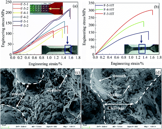 | ||
| Fig. 8 Tensile curves and fracture morphologies of Ti64 lattice structures with different states: (a and c) of SLM-ed, (b and d) of HT-ed. | ||
The fracture morphologies of lattice structures are shown in Fig. 8c and d. The fracture morphology of SLM-ed consists of a small amount of shallow dimples and large smooth plane (Fig. 8c), which means that the main fracture mechanism is brittle fracture. The fracture morphology of HT-ed (Fig. 8d) shows similar fracture characteristics to the SLM-ed alloy, but the depth of dimples became deeper and there are a lot of cleavage planes. These results demonstrate that the fracture mechanism of HT-ed is quasi-cleavage fracture. This also proves that the multi-scale α-laths and nano-β particles make the HT-ed alloy have excellent comprehensive mechanical properties (high tensile strength and appropriate ductility).
4. Discussion
The results in present study indicate that the size of the SLM-ed lattice structure and heat treatment process affects the microstructure and phase composition of the Ti64 alloy, and play an important role in the mechanical properties of the lattice structure. Different from SLM-ed bulk alloys, the SLM-ed lattice structure samples are almost all acicular α′ martensite, and there is no residual β phase. This is due to the smaller size of the lattice structure resulted from faster cooling (>106 K s−1). The double solution-aging heat treatment reduces the dislocations and crystal defects of the SLM-ed alloy while obtaining a controllable mixed structure, ensuring the integrity and stability of the implant.As shown in Fig. 9a and b, the elastic modulus and the tensile strength of the HT-ed alloy and the SLM-ed alloy decreases with the increase of porosity. The heat treatment makes α′ martensite transform to α phase along the α′ phase grain boundary, V atom diffuses from the inside of α to the grain boundary, and β phase is generated along the V-rich region. Therefore, α + β lamellar structure is formed after solution treatment. After the aging treatment, the remaining β phase is divided into small strip-shaped aging α. The heat treatment not only eliminates the residual stress of the SLM-ed alloy, but also precipitates nano-β particles and small strips of aging α. The nano-sized β particles also were found in the Ti64 alloy fabricated by spark plasma sintering after aging at 450 °C.32 These factors make the tensile strength and elastic modulus of HT-ed alloy higher than that of the SLM-ed one. In addition, the numerical fluctuation of Young's modulus and tensile strength of HT-ed alloys is smaller, showing that the HT-ed microstructure is homogenized and the residual stress is eliminated.
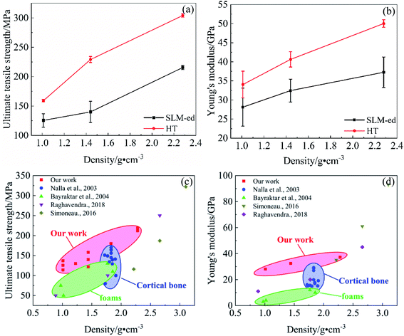 | ||
| Fig. 9 (a) Tensile strength and (b) Young's modulus of the SLM-ed and HT-ed versus the density; (c) tensile strength and (d) Young's modulus versus density for various lattice structure, including our work, cortical bone, and bending-dominated lattice material.33–36 | ||
Fig. 9c and d summarizes the tensile strength of human bone,33 bending-dominated lattice structure (foam),34 and stretch-dominated lattice structure (F2CCZ). Similar to the compression behavior of the lattice structure,9 the tensile strength and Young's modulus of the stretch-dominant lattice structure are higher than those of the bending-dominant lattice structure. This is due to the higher load-bearing capacity and higher structural efficiency. Compared with human bone, the tensile strength of SLM-ed lattice structure Ti64 is much higher than that of human bone at the same density, and the Young's modulus is also close to that of human bone. The results show that the special heat treatment can homogenize the microstructure and reduce the residual stress while also improving its tensile strength.
A number of predictive models have been proposed to relate void topology and material property parameters to mechanical properties. The most noted one is the Gibson–Ashby model,37 described by the following equation for different cellular solids.
 | (4) |
 | (5) |
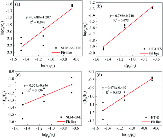
Fig. 10 plots the ultimate strength vs. density and modulus vs. density on the logarithmic scale for both SLM-ed and HT-ed alloys using the data listed in Fig. 9. The mechanical properties of the SLM-ed alloys are relatively dispersed, and the R2 value (0.536–0.847) is small. After heat treatment, the sample obtained a high R2 value (0.893–0.975), indicating that the Gibson–Ashby model can be used to describe the SLM Ti64 lattice after the residual stress is removed. This observation also shows that the value of R2 after heat treatment is close to 1, which means the data is more stable and reliable.
Table 5 summarizes the regression analysis of reported lattice structure experimental data. According to Gibson–Ashby theory, the C value should be in the range of 0.1–4.0. In this study, the values of C are 0.17 and 0.39 for the SLM-ed and HT-ed alloys, respectively. The increase of C value after heat treatment also represents the increase of tensile strength and Young's modulus. On the other hand, the smaller the value of n, the higher the stability and utilization of the lattice material. Compared with other bending-dominant lattice structures, the stretch-dominant lattice structure has a smaller n value and higher load-bearing capacity. Correlations were generally higher for strength than they were for modulus, though only marginally. Comparisons between the derived exponents and those predicted by the Gibson–Ashby model for bending and stretch-dominated structures provides insight into the general behavior of these topologies. For example, the exponent for the strength of FCCZ (n = 1.59) is very close to that predicted for stretch-dominated structures (n = 1.5), suggesting this topology behaves more like a stretch-dominated structure despite being bending-dominated according to the Maxwell criterion. In addition, in Table 5, it is found that when the simulated n value is less than 1, its R2 value drops rapidly, and can even be as low as 0.094. However, the values of n in this work are all lower than 1, and the minimum R2 is 0.536 and the maximum is 0.975. This shows that the structure of this study is more stable and reliable.
| Unit cell topology | Tensile strength | Young's modulus | Ref. | ||||
|---|---|---|---|---|---|---|---|
| n1 | C1 | Correlation (R2) | n2 | C2 | Correlation (R2) | ||
| F2CCZ-SLM-ed | 0.69 | 0.17 | 0.847 | 0.35 | 0.19 | 0.536 | This work |
| F2CCZ-HT-ed | 0.79 | 0.39 | 0.975 | 0.48 | 0.37 | 0.893 | This work |
| Diamond | 0.55 | 0.08 | 0.094 | 0.86 | 0.04 | 0.220 | 39 |
| FCC | 1.75 | 1.18 | 0.998 | 1.94 | 0.37 | 0.999 | 40 |
| BCCZ | 0.48 | 0.06 | 0.388 | 0.22 | 0.01 | 0.124 | 41 |
| Dodecahedron | 2.51 | 2.21 | 0.990 | 2.64 | 0.63 | 0.999 | 41 |
| Schwartz diamond | 1.36 | 0.77 | 0.997 | 0.76 | 0.05 | 0.966 | 42 |
| FCCZ | 1.59 | 1.32 | 0.994 | 1.50 | 0.35 | 0.919 | 41 |
| FBCCZ | 1.72 | 1.40 | 0.953 | 0.54 | 0.03 | 0.466 | 40 |
5. Conclusions
In this work, Ti64 lattice structure was designed and fabricated by SLM, and the influence of double solid solution-aging treatment on Ti64 lattice structures, including the microstructure and tensile properties were investigated. The following conclusions were obtained.(1) The size of the F2CCZ struts along the build direction is close to the design value, and the error does not exceed 30 μm. However, the dimensional error of the inclined struts at 45° to the build direction can be up to 140 μm.
(2) SLM-ed specimens have high dislocation density and residual stress, causing serious stress concentration at the junction of lattice and solid under tensile load. The double solution aging treatment not only eliminates the residual stress and dislocation, but also produces multi-scale microstructures (multi-scale α laths and β nanoparticles). The F-4 sample has the largest increase in tensile strength is from 140 ± 18 MPa for the SLM-ed alloy to 229 ± 5.1 MPa for the HT-ed alloy.
(3) According to the Gibson–Ashby model, the n values of SLM-ed and HT-ed alloys are both less than 1, which means that the F2CCZ structure has high stability and material utilization. However, the correlation coefficient (R2) of the HT-ed alloy is closer to 1, indicating that the sample is more suitable for the Gibson–Ashby model.
Conflicts of interest
There are no conflicts to declare.Acknowledgements
This research was funded by the National Natural Science Foundation of China (No. 51671152, No. 51874225, No. 51504191), the Natural Science Basic Research Plan in Shaanxi Province of China (No. 2014JM6229), Shaanxi Provincial Department of Education Industrialization Project (No. 18JC091), the Science and Technology Bureau of Xi'an (No. CXYZKD001) and Shaanxi Provincial Department of Education Natural Science Special Project (No. 14JK1512).References
- D. Zhang, D. Qiu and M. A. Gibson, et al., Additive manufacturing of ultrafine-grained high-strength titanium alloys, Nature, 2019, 576(7785), 91–95 CrossRef CAS PubMed.
- N. Taniguchi, S. Fujibayashi and M. Takemoto, et al., Effect of pore size on bone ingrowth into porous titanium implants fabricated by additive manufacturing: An in vivo experiment, Mater. Sci. Eng., C, 2016, 59, 690–701 CrossRef CAS PubMed.
- X. Z. Zhang, M. Leary and H. P. Tang, et al., Selective electron beam manufactured Ti-6Al-4V lattice structures for orthopedic implant applications: Current status and outstanding challenges, Curr. Opin. Solid State Mater. Sci., 2018, 22(3), 75–99 CrossRef CAS.
- B. V. Krishna, S. Bose and A. Bandyopadhyay, Low stiffness porous Ti structures for load-bearing implants, Acta Biomater., 2007, 3(6), 997–1006 CrossRef CAS PubMed.
- Q. Chen and G. A. Thouas, Metallic implant biomaterials, Mater. Sci. Eng., R, 2015, 87, 1–57 CrossRef.
- M. Zhang, Y. Yang and D. Wang, et al., Effect of heat treatment on the microstructure and mechanical properties of Ti6Al4V gradient structures manufactured by selective laser melting, Mater. Sci. Eng., A, 2018, 736, 288–297 CrossRef CAS.
- C. J. Todaro, M. A. Easton and D. Qiu, et al., Grain structure control during metal 3D printing by high-intensity ultrasound, Nat. Commun., 2020, 11(1), 142 CrossRef CAS PubMed.
- P. Wang, H. Zhou and L. Zhang, et al., In situ X-ray micro-computed tomography study of the damage evolution of prefabricated through-holes in SLM-Printed AlSi10Mg alloy under tension, J. Alloys Compd., 2020, 821, 153576 CrossRef CAS.
- M. Mazur, M. Leary and S. Sun, et al., Deformation and failure behaviour of Ti-6Al-4V lattice structures manufactured by selective laser melting (SLM), Int. J. Adv. Des. Manuf. Technol., 2016, 84(5–8), 1391–1411 Search PubMed.
- S. Gangireddy, M. Komarasamy and E. J. Faierson, et al., High strain rate mechanical behavior of Ti-6Al-4V octet lattice structures additively manufactured by selective laser melting (SLM), Mater. Sci. Eng., A, 2019, 745, 231–239 CrossRef CAS.
- Y. Xu, D. Zhang and Y. Guo, et al., Microstructural tailoring of As-Selective Laser Melted Ti6Al4V alloy for high mechanical properties, J. Alloys Compd., 2020, 816(5), 152536 CrossRef CAS.
- R. Chapurlat, M. Bui and E. Sornay-Rendu, et al., Deterioration of Cortical and Trabecular Microstructure Identifies Women With Osteopenia or Normal Bone Mineral Density at Imminent and Long-Term Risk for Fragility Fracture: A Prospective Study, J. Bone Miner. Res., 2020, 35(5), 833–844 CrossRef CAS.
- S. Raghavendra, A. Molinari and V. Fontanari, et al., Tensile and compression properties of variously arranged porous Ti-6Al-4V additively manufactured structures via SLM, Procedia Structural Integrity, 2018, 13, 6 CrossRef.
- S. M. Ahmadi, R. K. Ashok Kumar Jain and A. A. Zadpoor, et al., Effects of heat treatment on microstructure and mechanical behaviour of additive manufactured porous Ti6Al4V, IOP Conf. Ser.: Mater. Sci. Eng., 2018, 293, 012009 Search PubMed.
- S. Patil, S. Kekade and K. Phapale, et al., Effect of α and β Phase Volume Fraction on Machining Characteristics of Titanium Alloy Ti6Al4V, Procedia Manuf., 2016, 6, 63–70 CrossRef.
- Z. Guoqing, Y. Yongqiang and L. Hui, et al., Modeling and Manufacturing Technology for Personalized Biological Fixed Implants, J. Med. Biol. Eng., 2017, 37(2), 191–200 CrossRef.
- D. Wang, S. Mai and D. Xiao, et al., Surface quality of the curved overhanging structure manufactured from 316-L stainless steel by SLM, Int. J. Adv. Des. Manuf. Technol., 2015, 86(1–4), 781–792 Search PubMed.
- D. Wang, S. Wu and Y. Bai, et al., Characteristics of typical geometrical features shaped by selective laser melting, J. Laser Appl., 2017, 29(2), 022007 CrossRef.
- Y. Xu, Y. Lu and K. L. Sundberg, et al., Effect of Annealing Treatments on the Microstructure, Mechanical Properties and Corrosion Behavior of Direct Metal Laser Sintered Ti-6Al-4V, J. Mater. Eng. Perform., 2017, 26(6), 2572–2582 CrossRef CAS.
- W. Yuan, W. Hou and S. Li, et al., Heat treatment enhancing the compressive fatigue properties of open-cellular Ti-6Al-4V alloy prototypes fabricated by electron beam melting, J. Mater. Sci. Technol., 2018, 34(7), 1127–1131 CrossRef.
- T. Vilaro, C. Colin and J. D. Bartout, As-Fabricated and Heat-Treated Microstructures of the Ti-6Al-4V Alloy Processed by Selective Laser Melting, Metall. Mater. Trans. A, 2011, 42(10), 3190–3199 CrossRef CAS.
- B. Vrancken, L. Thijs and J.-P. Kruth, et al., Heat treatment of Ti6Al4V produced by Selective Laser Melting: Microstructure and mechanical properties, J. Alloys Compd., 2012, 541, 177–185 CrossRef CAS.
- M. Simonelli, Y. Y. Tse and C. Tuck, Effect of the build orientation on the mechanical properties and fracture modes of SLM Ti–6Al–4V, Mater. Sci. Eng., A, 2014, 616, 1–11 CrossRef CAS.
- J. J. de Damborenea, M. A. Arenas and M. A. Larosa, et al., Corrosion of Ti6Al4V pins produced by direct metal laser sintering, Appl. Surf. Sci., 2017, 393, 340–347 CrossRef CAS.
- M.-W. Wu, J.-K. Chen and B.-H. Lin, et al., Improved fatigue endurance ratio of additive manufactured Ti-6Al-4V lattice by hot isostatic pressing, Mater. Des., 2017, 134, 163–170 CrossRef CAS.
- H. Zhang, X. Liu and S. Yang, et al., The clarification of α′′ phase precipitate from β phase in Ti-15Mn alloy by mismatch theory, Mater. Lett., 2017, 202, 138–141 CrossRef CAS.
- W. Wan, D. Yi and H. Liu, et al., Observation and characterization of isothermal α′′ in a new β-type titanium alloy, Philos. Mag. Lett., 2016, 96(3), 90–96 CrossRef CAS.
- I. Yadroitsev, P. Krakhmalev and I. Yadroitsava, et al., Selective laser melting of Ti6Al4V alloy for biomedical applications: Temperature monitoring and microstructural evolution, J. Alloys Compd., 2014, 583, 404–409 CrossRef CAS.
- N. Hrabe, T. Gnäupel-Herold and T. Quinn, Fatigue properties of a titanium alloy (Ti–6Al–4V) fabricated via electron beam melting (EBM): Effects of internal defects and residual stress, Int. J. Fatigue, 2017, 94, 202–210 CrossRef CAS.
- V. Cain, L. Thijs and J. Van Humbeeck, et al., Crack propagation and fracture toughness of Ti6Al4V alloy produced by selective laser melting, Addit. Manuf., 2015, 5, 68–76 CAS.
- Z. Wang, S. Y. Tang and S. Scudino, et al., Additive manufacturing of a martensitic Co–Cr–Mo alloy: Towards circumventing the strength–ductility trade-off, Addit. Manuf., 2021, 37, 101725 CAS.
- Y. S. Zhang, J. J. Hu and Y. Q. Zhao, et al., Microstructure and mechanical properties of a high-oxygen core-shell network structured Ti6Al4V alloy, Vacuum, 2018, 149, 140–145 CrossRef CAS.
- R. K. Nalla, J. H. Kinney and R. O. Ritchie, Mechanistic fracture criteria for the failure of human cortical bone, Nat. Mater., 2003, 2(3), 164–168 CrossRef CAS PubMed.
- H. H. Bayraktar, E. F. Morgan and G. L. Niebur, et al., Comparison of the elastic and yield properties of human femoral trabecular and cortical bone tissue, J. Biomech., 2004, 37(1), 27–35 CrossRef.
- C. Simoneau, V. Brailovski and P. Terriault, Design, manufacture and tensile properties of stochastic porous metallic structures, Mech. Mater., 2016, 94, 26–37 CrossRef.
- S. Raghavendra, A. Molinari and V. Fontanari, et al., Tensile and compression properties of variously arranged porous Ti-6Al-4V additively manufactured structures via SLM, Procedia Structural Integrity, 2018, 13, 149–154 CrossRef.
- M. F. Ashby, A. Evans and N. A. Fleck, et al., Metal foams: a design guide, Mater. Des., 2002, 23, 2 CrossRef.
- S. Liu and Y. C. Shin, Additive manufacturing of Ti6Al4V alloy: A review, Mater. Des., 2019, 164, 107552 CrossRef CAS.
- S. M. Ahmadi, G. Campoli and S. Amin Yavari, et al., Mechanical behavior of regular open-cell porous biomaterials made of diamond lattice unit cells, J. Mech. Behav. Biomed. Mater., 2014, 34, 106–115 CrossRef CAS PubMed.
- T. Maconachie, M. Leary and B. Lozanovski, et al., SLM lattice structures: Properties, performance, applications and challenges, Mater. Des., 2019, 183, 108137 CrossRef.
- S. A. Yavari, R. Wauthle and J. van der Stok, et al., Fatigue behavior of porous biomaterials manufactured using selective laser melting, Mater. Sci. Eng., C, 2013, 33(8), 4849–4858 CrossRef PubMed.
- C. Yan, L. Hao and A. Hussein, et al., Ti-6Al-4V triply periodic minimal surface structures for bone implants fabricated via selective laser melting, J. Mech. Behav. Biomed. Mater., 2015, 51, 61–73 CrossRef CAS PubMed.
| This journal is © The Royal Society of Chemistry 2021 |

