 Open Access Article
Elevated electrochemical performances enabled by a core–shell titanium hydride coated separator in lithium–sulphur batteries†
Zhiyuan Zhao,
Xiaobo Duan *,
Lei Zhang,
Zhiwei Che,
Kun Wang,
Bin Zheng
 * and
Xiaogang Wang
Department of Materials Science & Engineering, Xi'an University of Science and Technology, Xi'an 710054, China. E-mail: xiaobo12558@163.com; zhengbin@xust.edu.cn
First published on 15th September 2021
Abstract
To date, the lithium–sulphur battery is still suffering from fast capacity fade and poor rate performance due to its special electrochemical mechanism. The interlayer or separator with conductive coatings is considered effective in inhibiting the shuttle effect. Here, we proposed a novel metal hydride with high conductivity and preferably chose TiH2 as the conductive coating because of its low cost, high conductivity, and good stability in air. The TiH2 powder was prepared by a simple ball-milling method, and the effect of the atmosphere was also investigated. A core–shell heterostructure formed, in which the TiH2 core acted as an electron transfer pathway, and the titanium oxide nano-shell functioned as the absorber for polysulfides. Thus, with the combination of fast electronic transfer and strong absorption ability, the TiH2 coated separator could improve the cycling stability, the rate performances, and the self-discharge rate. The TiH2 separator could increase the capacity of the lower plateau and delay the oversaturation points at high rates, promoting the liquid–solid conversion. It is believed that the promotion resulted from the high conductivity and polysulfide absorption of the TiH2 separator. Although the preparation process still needs further optimization, the core–shell metal hydride provided a novel strategy for designing the heterostructure, which could provide high conductivity and strong absorption ability toward polysulfides simultaneously.
Introduction
The lithium–sulphur battery is considered one of the most promising high-energy batteries due to its high theoretical energy density (2600 W h kg−1), low cost, and environmental sustainability. However, the sluggish kinetics and the poor cycle stability resulting from the insulating nature of solid sulphur species and the unlimited diffusion of polysulfides are hindering the commercialisation of the lithium–sulphur battery. Polysulfide intermediates, the most important difference between lithium–sulphur batteries and other battery systems, are believed to play a positive role in promoting the sulphur conversion reaction as the redox mediators, but also corrode the metallic lithium and cause the irreversible loss of sulphur species, giving researchers a dilemma.1 So, how to manage polysulfides rationally is a key issue in the lithium–sulphur battery.In the last years, great progress has been made to solve these problems. The detailed methods include (1) using porous materials as hosts;2–6 (2) designing new electrolytes;7–9 (3) protecting the metallic lithium anode from the corrosion of polysulfides;10–13 (4) polysulfide-inhibiting interlayer or separator.14–16 Among them, the specially designed separator or interlayer usually traps polysulfides by physical and chemical confinement and also reactive the dead sulphur species, boosting the electrochemical performances of lithium–sulphur batteries. A typical polysulfide-inhibiting interlayer or functioned separator is covered by conductive materials, commonly carbonaceous materials, due to its low cost and adequate conductivity. For example, Arumugam Manthiram proposed the MWCNT interlayer in lithium–sulphur batteries firstly, reduced the charge transfer resistance of the sulphur cathodes and the loss of the dissolved intermediates.17 Yi Cui compared the effects of conductive materials as polysulfides barrier on the electrochemical performances and discovered that higher electronic conductivity of the coated separators resulted in greater improvements.18
Despite the progress obtained, the weak interaction of nonpolar carbon with polysulfides results in a poor trap of polysulfides, causing the corrosion of lithium anode and the loss of active materials. Many researchers turn their attention to polar compounds gradually, such as oxides,19,20 sulfides,21,22 metal–boron compounds,23,24 metal–C compounds,25,26 which exhibit the stronger absorption and catalytic ability for polysulfides. TiO2, a typical polar semi-conducting oxide, has been studied intensively in lithium–sulphur batteries. Its absorption ability and electrical conductivity could be enhanced by band engineering including doping and oxygen defects.27 However, TiO2 has no adequate conductivity even after modification and must couple with conductive carbon materials. Thus, these materials exhibiting strong interactions with polysulfides and high conductivities are preferred. Consequently, other titanium compounds, such as TiC,28 TiB2,23 TiN,29,30 Ti4O7,31 TiO,32 Ti2O,33 have attracted great attention.
Herein, we proposed a novel material system, transition metal hydrides, as the conductive coating on the Celgard separators. These hydrides usually exhibit excellent electron conductivities and were easily ground to fine powder due to their high fragility. TiH2, one of the cheapest and most stable metal hydrides in the ambient atmosphere, was preferentially chosen as the conductive coating on the separator here because it exhibits an excellent conductivity (∼104 S cm−1)34 and can be sufficiently supplied at a large scale in the titanium metallurgy industry. Moreover, it also exhibits high fragility, which means that the fine TiH2 powder can be produced mechanically at a low cost. During the preparation process, a titanium oxide nano-film in situ formed in air and covered the TiH2 core due to the medium activity of titanium hydride toward oxygen. The core–shell microstructure combined the high electron conductivity of TiH2 with the absorption ability of polar titanium oxides. Unsurprisingly, the TiH2 coated separator could improve the electrochemical performance of the lithium–sulphur battery.
Experimental
Preparation of the TiH2 coated separators
The purchased commercial TiH2 raw powder (∼100 mesh) was milled for 2 hours in an Ar-filled MSK-SFM-3 high energy ball miller with a ball material ratio of 5![[thin space (1/6-em)]](https://www.rsc.org/images/entities/char_2009.gif) :
:![[thin space (1/6-em)]](https://www.rsc.org/images/entities/char_2009.gif) 1. 0.9 g milled powder was mixed with 0.1 g PVDF (polyvinylidene fluoride), and then an appropriate amount of NMP (1-methyl-2-pyrrolidinone) was added to form a viscous slurry. The slurry was coated on the commercial separators (Celgard 2520) with the doctor blade coater. The coated separator was heated for 12 hours under vacuum to remove NMP and then cut into the disks with diameters of 18 mm. The TiH2 loading was controlled to ∼1.5 mg cm−2.
1. 0.9 g milled powder was mixed with 0.1 g PVDF (polyvinylidene fluoride), and then an appropriate amount of NMP (1-methyl-2-pyrrolidinone) was added to form a viscous slurry. The slurry was coated on the commercial separators (Celgard 2520) with the doctor blade coater. The coated separator was heated for 12 hours under vacuum to remove NMP and then cut into the disks with diameters of 18 mm. The TiH2 loading was controlled to ∼1.5 mg cm−2.
Preparation of the sulphur cathodes
Typically, 0.7 g commercial sulphur powder was mixed with 0.2 g carbon black (EC-300J) and heated at 150 °C for 10 hours. The obtain S/C powder was ground and mixed with 0.1 g PVDF. Then, an appropriate amount of NMP was also added to form a viscous slurry. The slurry was coated on Al foil with a doctor blade coater. The sulphur cathode was dried at 60 °C for 24 h in air and cut into disks after drying. The sulphur loading was controlled to 2.7–3 mg cm−2.Electrochemical measurement
The CR2025 coin cell was assembled in argon filled glove box with moisture and oxygen contents of <0.1 ppm. A lithium metal foil was used as the counter electrode and a solution of 1 M bis(trifluoromethane)sulfonamide lithium salt (LiTFSI) and 2 wt% LiNO3 dissolved in dimethoxymethane (DME): 1,3-dioxolane (DOL) (v/v = 1![[thin space (1/6-em)]](https://www.rsc.org/images/entities/char_2009.gif) :
:![[thin space (1/6-em)]](https://www.rsc.org/images/entities/char_2009.gif) 1) mixture.
1) mixture.
The charge–discharge measurements were performed at Land 2001A battery tester at various rates, where 1C was set to 1675 mA g−1. The electrochemical impedance measurements were carried out using a CHI 660D electrochemical workstation at open-circuit voltage with a voltage of amplitude of 10 mV and a frequency range from 0.1 to 105 Hz. The cyclic voltammetry measurements were also conducted at CHI 660D electrochemical workstation with a voltage window of 1.7–3.0 V at various scan rates.
Polysulfide adsorption study and XPS sample preparation
0.02 M Li2S6 solution was prepared by adding an appropriate amount of Li2S and S8 in DME solution with stirring at room temperature. 0.5 g TiH2 powder was added in 4.2 mL Li2S6 solution to inspect the colour change after 10 min standing. Afterwards, the solution was filtered and the solids for XPS analysis were obtained after drying in vacuo for 10 h.Material characterization
The morphology and structure were investigated by field emission scanning electron microscopy (FE-SEM, Zeiss) and field-emission transmission electron microscopy (TEM, JEM-2800) coupled with Energy Dispersive Spectrometer (EDS). The electrical conductivities were measured by a standard four-point-probe powder resistivity measurement system (ST2253) with a pressure of 10 Mpa. The phases of TiH2 powder were determined by X-ray diffraction (XRD, Shimadzu 7000). X-ray photoelectron spectroscopy (XPS) measurements were performed on Kratos Thermo Scientific K-Alpha+ instrument coupled with an Ar-filled glovebox for the sample transfer under Ar protection, using monochromated Al Kα X-rays as the excitation source with an accelerating voltage of 15 kV and a beam of 15 mA. The ionic conductivity measurements of the separators were carried out on CHI660D via the impedance–time method (1 kHz) according to the reported calculation equation.35,36 The polysulfides diffusion test was carried out in an H type cell. The left chamber was filled with 0.02 mol L−1 Li2S6 DME solution and the right was pure DME solution. The separator was placed between the left and the right chamber.Results and discussion
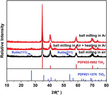
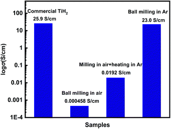
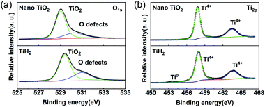
Commercial TiH2 powder is usually supplied as raw and coarse particles, which is considered detrimental to the absorption of polysulfides due to its low specific surface area. Reducing the sizes of the commercial TiH2 particles is vital. Fortunately, TiH2 exhibits extremely high fragility, which favours reducing the particle sizes mechanically by a simple ball milling method. Fig. 1 shows the XRD patterns of the purchased TiH2 powder milled in Ar and air. The anatase TiO2 peaks are obvious in the XRD pattern of TiH2 milled in air, indicating that TiH2 powder was easily oxidized after ball milling in air due to its high activity toward oxygen. Undoubtedly, too much TiO2 on the surface of the TiH2 particles would lower the electron transfer kinetics. After being milled in air, the TiH2 powder showed a dramatically decreased conductivity of 0.000458 S cm−1 (Fig. 2), suggesting the negative role of the TiO2. The microstructure of the TiH2 milled in air and Ar was similar (Fig. S1†), implying the dramatic decrease of the conductivity should be associated with the formation of TiO2 rather than the microstructure change. Even after heated in Ar, the oxidized TiH2 powder was not resumed completely. The anatase TiO2 peaks were still obvious and the increased conductivity of 0.0192 S cm−1 was still insufficient for lithium–sulphur batteries. Accordingly, the inert atmosphere was considered essential to obtain highly conductive TiH2 powder in the ball milling process. Under the protection of the Ar atmosphere, no obvious characteristic peak of Ti–O compounds was observed. Correspondingly, the milled TiH2 powder exhibited rather high conductivity (23 S cm−1), approaching the level of the raw TiH2 powder and even higher than carbon black and Ti4O7.37,38 The conductivity was considered rather suitable for the coated separator in lithium–sulphur batteries. Similarly, the conductivities of the commercial Ti4O7 powder milled in Ar or air were also measured and the results highlighted the importance of inert atmosphere during milling (Fig. S2†).The XPS spectra of TiH2 powder milled in Ar could provide more information about the chemical composition and states on the surface of the TiH2 powder. According to the chemical composition information shown in Table S1,† the oxygen content was rather higher unexpectedly. The Ti 2p spectra (Fig. 3a) also show typical Ti 2p1/2 and Ti 2p3/2 peaks for Ti4+ ions, just like the spectrum of nano TiO2, indicating that a titanium oxide layer formed on the surface of the TiH2 particles. Besides the Ti4+ peaks, the typical Ti0 peak also was observed, implying that the thickness of the titanium oxide layer was at the nanometer scale because the detective depth of XPS is only several nanometers. The O 1s spectra (Fig. 3b) show that the titanium oxide layer formed at room temperature contained more oxygen defects than the commercial nano TiO2 particles, indicating that the crystallization degree was lower. According to the previous work,27 the oxygen defects could narrow the bandgap of TiO2, trap polysulfides, and accelerate the polysulfides conversion. Thus, the oxygen defect-rich TiO2−x could be considered beneficial for the cycle and rate performances in lithium–sulphur batteries.39–43
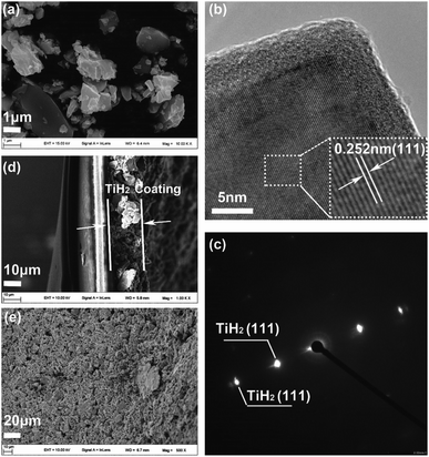
Considering the important role of the surface in absorption and catalytic behaviours, SEM and TEM were used to explore the titanium oxide layer, as shown in Fig. 4. Fig. 4a shows that the TiH2 particle sizes ranged from several micrometres to sub-micrometres. In the higher magnitude view provided by TEM (Fig. S3†), the existence of the formed oxide layer was evidenced by the Ti and O mapping. Further, the HRTEM image (Fig. 4b) shows the oxide layer had a low crystallinity degree, distinguished from the ordered TiH2 core. The corresponding SAED pattern in Fig. 4c only reveals the clear diffraction spots indexed as (111) plane of TiH2 (Fd![[3 with combining macron]](https://www.rsc.org/images/entities/char_0033_0304.gif) m). The oxide layer revealed no obvious electron diffraction spots, which may result from its lower amount and disordered characteristic. Because the oxide layer covered on the TiH2 particles was as thin as ∼5 nm, the electron could still transfer through the oxide layer by the quantum tunnelling effects, thus the TiH2 powder remained highly conductive. The surface of the commercial TiH2 powder was examined by XPS, SEM and TEM, which were shown in Fig. S4.† The results also showed the existence of the nano Ti–O layer on the commercial TiH2 particles, indicating the nano Ti–O layer formed spontaneously when the TiH2 particles were exposed to air, even at room temperature. The Ar atmosphere during milling could limit the formation of titanium oxides, avoiding the dramatic decrease of the electrical conductivity. However, air could cause too severe oxidation, even to the extent that the titanium oxides could be detected by XRD. Unsurprisingly, the electrical conductivity of the TiH2 powder milled in air decreased dramatically. Fig. 4d and e show the cross-section and surface images of the TiH2 separator. It can be seen that a porous TiH2 layer of 15–20 μm covered the commercial plastic separator.
m). The oxide layer revealed no obvious electron diffraction spots, which may result from its lower amount and disordered characteristic. Because the oxide layer covered on the TiH2 particles was as thin as ∼5 nm, the electron could still transfer through the oxide layer by the quantum tunnelling effects, thus the TiH2 powder remained highly conductive. The surface of the commercial TiH2 powder was examined by XPS, SEM and TEM, which were shown in Fig. S4.† The results also showed the existence of the nano Ti–O layer on the commercial TiH2 particles, indicating the nano Ti–O layer formed spontaneously when the TiH2 particles were exposed to air, even at room temperature. The Ar atmosphere during milling could limit the formation of titanium oxides, avoiding the dramatic decrease of the electrical conductivity. However, air could cause too severe oxidation, even to the extent that the titanium oxides could be detected by XRD. Unsurprisingly, the electrical conductivity of the TiH2 powder milled in air decreased dramatically. Fig. 4d and e show the cross-section and surface images of the TiH2 separator. It can be seen that a porous TiH2 layer of 15–20 μm covered the commercial plastic separator.
Since a disordered TiO2 nanofilm covered the TiH2 core, the previous researches on the polysulfides absorption characteristics of TiO2 could provide more guides. It is well known that TiO2 with oxygen defects is a good polysulfide absorber. Unsurprisingly, the TiH2 powder also exhibited its absorption ability of polysulfide in Li2S6 solution due to its Ti–O shell (Fig. S5†). Here, XPS also were used to clarify the absorption mechanism of the polysulfides. ∼0.55 eV chemical shift is observed in the Ti 2p spectrum after the TiH2 powder absorbed polysulfides (Fig. S6†). The blue chemical shift was also observed in other titanium oxides due to the electron transfer from Li2Sn to Ti–O.43 This blue shift was used to verify the presence of Ti–S interaction by some researchers.27 Meanwhile, the intensive S–O peaks in S 2p and O 1s spectra were discovered (Fig. 5c and d), which meant the polysulfides were absorbed on the titanium oxide layer via S–O interaction mainly. In previous researches, all the S–O interaction, Li–O interaction, and Ti–S interaction were discovered in the absorption of polysulfides on titanium oxides, but the dominating interaction is still controversial. For example, some researchers44 assumed TiO2 bound polysulfides via metal–S interaction instead of the S–O interaction because its redox potential fell out the redox potential window of polysulfides. Shujiang Ding et al. concluded that the Li–O and Ti–S interaction played an important role in binding the polysulfides on the surface of the CNT@TiO2−x composite.27 Xin Wang et al. revealed that the S–O peaks occurred before cycling while the Ti–S peak also appeared after cycling, but the detailed mechanism was not fully elucidated.41,45 However, Ning Liu et al. discovered the opposite results.46 Despite the uncertain mechanism, intensive researches have proved TiO2 to be a strong absorber toward polysulfides. Here, the TiO2−x nano-shell also proved its similar role. Thus, The TiH2 powder coated separator also exhibited a better polysulfides-inhibiting property compared with the Celgard separator, as shown in Fig. S7.†
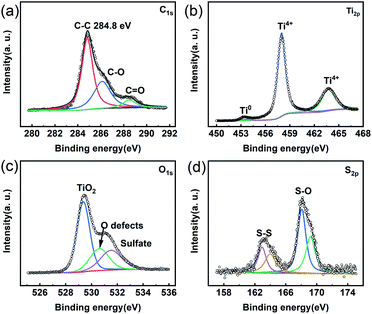 | ||
| Fig. 5 XPS spectra of the TiH2 powder soaked in Li2S6 solution. (a) C 1s. (b) Ti 2p (c) O 1s. (d) S 2p. | ||
As a coating material in the lithium–sulphur battery, the electrochemical stability was firstly evaluated, as shown in Fig. S8.† It can be seen that the TiH2 powder itself delivered a low specific capacity (∼5 mA h g−1) in 1–3 V, mainly from its capacitive charge/discharge behaviour. The TiH2 powder showed admirable electrochemical stability.
Besides electrochemical stability, ionic conductivity is also an important issue for separators. The TiH2 and Celgard separator was 0.74 mS cm−1 and 0.64 mS cm−1, whereas the total ionic resistance was 3.65 Ω and 1.98 Ω (Table S2†). The total ionic resistance may be a better quantitative parameter for these separators due to their different thickness. Because of the higher thickness, the TiH2 separator exhibited higher total ionic resistance.
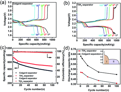
As the previous works reported, highly conductive materials coated separators were usually beneficial to the cycling performances of the lithium–sulphur battery, but whether the higher ionic resistance would deteriorate the electrochemical performances needed to be explored. Fig. 6 shows the electrochemical performances of the lithium–sulphur batteries with Celgard and TiH2 separators during cycling. For simplicity, the lithium–sulphur batteries with Celgard and TiH2 separators were named the Celgard battery and the TiH2 battery, respectively. From Fig. 6a and b, it can be seen that the lithium–sulphur batteries exhibited similar initial capacities. However, the lithium–sulphur battery with Celgard separator degraded rapidly during cycling, especially in the initial stage. By contrast, the capacity of the lithium–sulphur battery with TiH2 separator degraded more slowly (Fig. 6c) and the increase of the discharge/charge polarizations were not observed during cycling, so the degradation cannot be attributed to the changes of the electrode's polarization. To explore the detailed degradation mechanism of the sulphur cathodes, we divided the discharge profiles into two regions according to the upper and lower voltage plateaus, corresponding to the S8 → Li2S4 and the Li2S4 → Li2S conversion process respectively, as shown in Fig. 6d. For simplicity, the capacities contributed by the upper and lower voltage plateaus were named Qupper and Qlower. From Fig. 6d, it can be seen that the ratios (Qupper/Qlower) for the two batteries both decreased during cycling, indicating that the lower voltage plateau degraded more rapidly compared with the upper voltage plateau. However, the initial Qupper/Qlower ratio for the Celgard battery was higher and decreased more rapidly, consistent with the results shown in Fig. 6a and b. It can be seen that the upper voltage plateau contributed more capacity in the TiH2 battery. It meant that the soluble long-chain polysulfides would react with the lithium anode for a longer time, promoting the S-containing species loss. Thus, the capacity decay rate of the Celgard battery increased inevitably. These phenomena could be explained by the inhibition behaviour of polysulfides from the TiH2 separator.
It is well known that the side-reaction of the long-chain polysulfides with metallic lithium should be responsible for severe self-discharge in lithium–sulphur batteries as well as the fast fading during cycling. Whether the polysulfides-inhibiting of the TiH2 separator would also improve the self-discharge performance was worth investigating. Fig. S9† shows their self-discharge performances. In the TiH2 battery, its open-circuit voltage decreased more slowly and the capacity loss was also smaller than the Celgard batteries after 200 h standing. This improvement could also prove the positive role of the TiH2 separator in suppressing the dissolution of polysulfides.
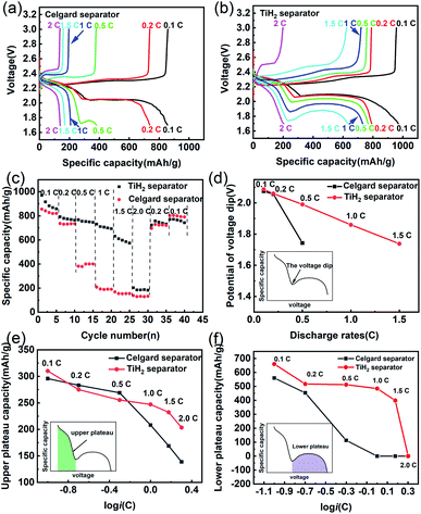
Besides the better cycle stability and self-discharge rate, it was also expected that the TiH2 separator could offer better rate performance due to its high electron conductivity from the TiH2 core and the absorption ability from the TiO2−x shell. The electrochemical performances of the lithium–sulphur batteries at various rates were shown in Fig. 7. In Fig. 7a and b, the TiH2 separator showed its advantages in capacities and polarizations at various rates, especially at 0.5C or higher rates. By comparison, at 0.5C or higher rates, the Celgard battery suffered from severe capacity degradation, which mainly resulted from the fading on the lower voltage plateau (Fig. 7a and b). At 1C and higher rates, the lower voltage plateau even disappeared.
In the discharge process, the upper plateau is usually assigned to the electrochemical conversion reaction from S8 to Li2S4, which has better reaction kinetics compared with the Li2S4 to Li2S conversion that occurred in the lower plateau. So, the lower plateau is more sensitive to the discharge rates and degraded faster at high rates. If the initial potential of the lower plateau, also called the voltage dip or the oversaturation point by some researchers,47,48 dropped below 1.7 V, the lower plateau would disappear, leading to the sharply dropped capacity, as shown in Fig. 7c. The oversaturation point corresponds to the barrier for the initial nucleation of Li2S and can be diminished by some redox mediators which promote the formation of Li2S.49 Fig. 7d shows the relationship between the oversaturation points and the discharge rates, and an approximately linear relationship can be observed in the TiH2 battery. At 0.1C and 0.2C, the oversaturation points occurred at similar potentials in the two batteries. When the discharge current increased to 0.5C, the oversaturation points in the Celgard battery dropped sharply and out of the cut-off voltage window at higher rates. It seems that the TiH2 separator could promote the nucleation of the solid discharge phase and thus diminish the voltage dip at the oversaturation points.
Fig. 7e and f show the capacities contributed by the upper and lower voltage plateau at various discharge rates, respectively. The approximative logarithmic relationship between the capacities contributed by the upper plateau (Qupper) and the discharge rates (i) was discovered in Fig. 7e, which indicated that the polarization probably resulted in the capacity decrease of the upper voltage plateau. In the Celgard battery, a sudden capacity fall was observed when the current increased to 0.5C. At higher rates, the capacities fell to zero due to the huge voltage dip. By contrast, the capacities contributed by the lower plateau remained relatively stable until the rate increased to 2C.
Based on the above description, it seems the lower plateau rather than the upper plateau had the primary responsibility for the huge rate differences between the Celgard battery and the TiH2 battery. Unlike the upper plateau, no apparent linear relationship between the capacities (Qlower) and log![[thin space (1/6-em)]](https://www.rsc.org/images/entities/char_2009.gif) i could be observed, indicating the capacity contributed by the lower plateau (Qlower) was affected by other factors, besides the polarization associated with the discharge rates. Yan Zhao42 studied the effect of the oxygen defects in TiO2−x on the polysulfides immobilization and catalytic conversion reactions by the first-principles computational characterization and experimental design. It was revealed that TiO2, especially the TiO2−x with oxygen defects, was capable of absorbing and catalysing the S-containing species, thus accelerating the transformation of S8 to Li2S. Other researchers obtained a similar conclusion on TiO2−x. Regardless of the detailed mechanism, it is quite certain that TiO2−x can absorb and catalyse the S-containing species. However, it was usually coupled with high conductive carbonaceous materials due to its poor conductivity. Some other metal oxides, such as VO2,50 MnO2,51 could also promote the polysulfides conversion via the S–O interaction. So, it could be inferred that the core–shell TiO2−x@TiH2 structure could combine the absorption and catalytic properties from the TiO2−x shell and the high conductivity from the TiH2 core, improving the electrochemical performances.
i could be observed, indicating the capacity contributed by the lower plateau (Qlower) was affected by other factors, besides the polarization associated with the discharge rates. Yan Zhao42 studied the effect of the oxygen defects in TiO2−x on the polysulfides immobilization and catalytic conversion reactions by the first-principles computational characterization and experimental design. It was revealed that TiO2, especially the TiO2−x with oxygen defects, was capable of absorbing and catalysing the S-containing species, thus accelerating the transformation of S8 to Li2S. Other researchers obtained a similar conclusion on TiO2−x. Regardless of the detailed mechanism, it is quite certain that TiO2−x can absorb and catalyse the S-containing species. However, it was usually coupled with high conductive carbonaceous materials due to its poor conductivity. Some other metal oxides, such as VO2,50 MnO2,51 could also promote the polysulfides conversion via the S–O interaction. So, it could be inferred that the core–shell TiO2−x@TiH2 structure could combine the absorption and catalytic properties from the TiO2−x shell and the high conductivity from the TiH2 core, improving the electrochemical performances.
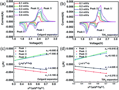
The CV tests with different scan rates were performed to study the reaction kinetic behaviours of the lithium–sulphur batteries with different separators. Consistent with the rate performances showed in Fig. 7, the lithium–sulphur battery with the TiH2 separator shows smaller polarizations and higher peak currents at various scan rates except for peak I, which was assigned to the conversion from S8 to Li2S4 (Fig. S10†). First, compared with the fast conversion from S8 to Li2S4, the conversion of Li2S4 to Li2S is more easily affected by the various eternal factors due to its sluggish kinetics. Second, it is also accepted that the charging process is relatively slower than the discharge process.37 So, it is easily understood why the TiH2 separator influenced the peaks differently. To further evaluate the effect of the TiH2 separator on the reaction kinetics quantitatively, the CV data were characterized by analysing the plots of ip vs. v0.5 according to the Randles–Sevcik equation at 298 K:52
Conclusions
A highly conductive titanium hydrogen powder with the core–shell microstructure was prepared by a facile, simple ball-milled method in Ar. The in situ formation of the core–shell structure could be attributed to the slight oxidation of the TiH2 powder and allowed the fast electronic transfer due to the quantum effect. As a polar titanium oxide layer, the shell also exhibited a strong absorption ability to the polysulfides, just like the titanium oxides in other works. The TiH2 coated separator could enhance the comprehensive electrochemical performance remarkably, including the cycling stability, rate performances, and self-discharge rates. It was concluded that these improvements resulted from the absorption of the polysulfide on the titanium oxide nano-shell, which could absorb the polysulfides and promote the conversion from soluble polysulfides to Li2S2 or Li2S. After further optimization, better polysulfide absorption and electronic transfer properties can be expected. Meanwhile, based on a similar principle, other transition metal hydrides can be used to form a corresponding core–shell microstructure. The shell should not be limited in the scope of oxides. Other compounds exhibiting strong affinities toward polysulfides are also optional. By controlling the atmosphere exposed during preparation, various core–shell heterostructures might be created and play more important roles in absorbing or catalysing the sulphur conversion.Conflicts of interest
There are no conflicts to declare.Acknowledgements
This work was supported by the National Natural Science Foundation of China (Grant No. 51602254), the Natural Science Foundation of Shaanxi Province (Grant No. 2020JQ-737).Notes and references
- G. Li, S. Wang, Y. Zhang, M. Li, Z. Chen and J. Lu, Adv. Mater., 2018, 30, 1705590 CrossRef PubMed.
- H. Choi, X. Zhao, D. S. Kim, H. J. Ahn, K. W. Kim, K. K. Cho and J. H. Ahn, Mater. Res. Bull., 2014, 58, 199–203 CrossRef CAS.
- Z. Xiao, D. Kong, Q. Song, S. Zhou, Y. Zhang, A. Badshah, J. Liang and L. Zhi, Nano Energy, 2018, 46, 365–371 CrossRef CAS.
- Z. Zheng, H. Guo, F. Pei, X. Zhang, X. Chen, X. Fang, T. Wang and N. Zheng, Adv. Funct. Mater., 2016, 26, 8952–8959 CrossRef CAS.
- L. Ji, M. Rao, S. Aloni, L. Wang, E. J. Cairns and Y. Zhang, Energy Environ. Sci., 2011, 4, 5053–5059 RSC.
- K. Gao, X. Guo, B. Zheng, J. Wang and L. Wang, Mater. Today Energy, 2021, 20, 100458 CAS.
- L. Suo, Y. S. Hu, H. Li, M. Armand and L. Chen, Nat. Commun., 2013, 4, 1–9 Search PubMed.
- M. Cuisinier, P. E. Cabelguen, B. D. Adams, A. Garsuch, M. Balasubramanian and L. F. Nazar, Energy Environ. Sci., 2014, 7, 2697–2705 RSC.
- H. Lu, Y. Zhu, Y. Yuan, L. He, B. Zheng, X. Zheng, C. Liu and H. Du, J. Mater. Sci.: Mater. Electron., 2021, 32, 5898–5906 CrossRef CAS.
- H. Kim, J. T. Lee, D. C. Lee, M. Oschatz, W. il Cho, S. Kaskel and G. Yushin, Electrochem. Commun., 2013, 36, 38–41 CrossRef CAS.
- H. K. Jing, L. L. Kong, S. Liu, G. R. Li and X. P. Gao, J. Mater. Chem. A, 2015, 3, 12213–12219 RSC.
- B. Duan, W. Wang, H. Zhao, A. Wang, M. Wang, K. Yuan, Z. Yu and Y. Yanga, ECS Electrochem. Lett., 2013, 2, A47 CrossRef CAS.
- C. Yan, X. B. Cheng, C. Z. Zhao, J. Q. Huang, S. T. Yang and Q. Zhang, J. Power Sources, 2016, 327, 212–220 CrossRef CAS.
- T. G. Jeong, Y. H. Moon, H. H. Chun, H. S. Kim, B. W. Cho and Y. T. Kim, Chem. Commun., 2013, 49, 11107–11109 RSC.
- B. Li, Z. Sun, Y. Zhao, Y. Tian, T. Tan, F. Gao and J. Li, J. Nanopart. Res., 2019, 21, 1–10 CrossRef CAS.
- S. H. Chung and A. Manthiram, J. Phys. Chem. Lett., 2014, 5, 1978–1983 CrossRef CAS PubMed.
- Y. S. Su and A. Manthiram, Chem. Commun., 2012, 48, 8817–8819 RSC.
- H. Yao, K. Yan, W. Li, G. Zheng, D. Kong, Z. W. Seh, V. K. Narasimhan, Z. Liang and Y. Cui, Energy Environ. Sci., 2014, 7, 3381–3390 RSC.
- Z. Xiao, Z. Yang, L. Wang, H. Nie, M. Zhong, Q. Lai, X. Xu, L. Zhang and S. Huang, Adv. Mater., 2015, 27, 2891–2898 CrossRef CAS PubMed.
- L. Luo, X. Qin, J. Wu, G. Liang, Q. Li, M. Liu, F. Kang, G. Chen and B. Li, J. Mater. Chem. A, 2018, 6, 8612–8619 RSC.
- Y. Yang, S. Wang, L. Zhang, Y. Deng, H. Xu, X. Qin and G. Chen, Chem. Eng. J., 2019, 369, 77–86 CrossRef CAS.
- S. Yao, J. Cui, J. Q. Huang, Z. Lu, Y. Deng, W. G. Chong, J. Wu, M. Ihsan Ul Haq, F. Ciucci and J. K. Kim, Adv. Energy Mater., 2018, 8, 1800710 CrossRef.
- L. Jin, J. Ni, C. Shen, F. Peng, Q. Wu, D. Ye, J. Zheng, G. Li, C. Zhang, Z. Li and J. P. Zheng, J. Power Sources, 2020, 448, 227336 CrossRef CAS.
- C. Li, X. Liu, L. Zhu, R. Huang, M. Zhao, L. Xu and Y. Qian, Chem. Mater., 2018, 30, 6969–6977 CrossRef CAS.
- W. Cai, G. Li, K. Zhang, G. Xiao, C. Wang, K. Ye, Z. Chen, Y. Zhu and Y. Qian, Adv. Funct. Mater., 2018, 28, 1704865 CrossRef.
- C. Lin, W. Zhang, L. Wang, Z. Wang, W. Zhao, W. Duan, Z. Zhao, B. Liu and J. Jin, J. Mater. Chem. A, 2016, 4, 5993–5998 RSC.
- Y. Wang, R. Zhang, J. Chen, H. Wu, S. Lu, K. Wang, H. Li, C. J. Harris, K. Xi, R. V. Kumar and S. Ding, Adv. Energy Mater., 2019, 9, 1900953 CrossRef.
- J. Zhao and Z. Yan, J. Alloys Compd., 2021, 856, 156609 CrossRef CAS.
- Z. Hao, L. Yuan, C. Chen, J. Xiang, Y. Li, Z. Huang, P. Hu and Y. Huang, J. Mater. Chem. A, 2016, 4, 17711–17717 RSC.
- W. G. Lim, C. Jo, A. Cho, J. Hwang, S. Kim, J. W. Han and J. Lee, Adv. Mater., 2019, 31, 1–9 Search PubMed.
- Y. Guo, J. Li, R. Pitcheri, J. Zhu, P. Wen and Y. Qiu, Chem. Eng. J., 2019, 355, 390–398 CrossRef CAS.
- Z. Li, L. Tang, X. Liu, T. Song, Q. Xu, H. Liu and Y. Wang, Electrochim. Acta, 2019, 310, 1–12 CrossRef CAS.
- R. Wang, K. Wang, H. Tao, W. Zhao, M. Jiang, J. Yan and K. Jiang, J. Mater. Chem. A, 2020, 8, 11224–11232 RSC.
- S. P. Murarka, S. H. Ko, P. J. Ding and W. A. Lanford, Mater. Res. Soc. Symp. Proc., 1994, 337, 217–224 CrossRef CAS.
- R. Zahn, M. F. Lagadec, M. Hess and V. Wood, ACS Appl. Mater. Interfaces, 2016, 8, 32637–32642 CrossRef CAS PubMed.
- M. Kim and J. H. Park, J. Power Sources, 2012, 212, 22–27 CrossRef CAS.
- X. Duan, Y. Han, L. Huang, Y. Li and Y. Chen, J. Mater. Chem. A, 2015, 3, 8015–8021 RSC.
- Q. Pang, D. Kundu, M. Cuisinier and L. F. Nazar, Nat. Commun., 2014, 5, 1–8 Search PubMed.
- W. Yao, W. Zheng, K. Han and S. Xiao, J. Mater. Chem. A, 2020, 8, 19028–19042 RSC.
- E. H. M. Salhabi, J. Zhao, J. Wang, M. Yang, B. Wang and D. Wang, Angew. Chem., Int. Ed., 2019, 58, 9078–9082 CrossRef CAS PubMed.
- N. Liu, H. Ma, L. Wang, Y. Zhao, Z. Bakenov and X. Wang, J. Mater. Sci. Technol., 2021, 84, 124–132 CrossRef.
- Q. He, B. Yu, H. Wang, M. Rana, X. Liao and Y. Zhao, Nano Res., 2020, 13, 2299–2307 CrossRef CAS.
- G. Chen, J. Li, N. Liu, Y. Zhao, J. Tao, G. Kalimuldina, Z. Bakenov and Y. Zhang, Electrochim. Acta, 2019, 326, 134968 CrossRef CAS.
- H. Ye and J. Y. Lee, Small Methods, 2020, 4, 1900864 CrossRef CAS.
- C. Li, Z. Li, Q. Li, Z. Zhang, S. Dong and L. Yin, Electrochim. Acta, 2016, 215, 689–698 CrossRef CAS.
- N. Liu, L. Wang, Y. Zhao, T. Tan and Y. Zhang, J. Alloys Compd., 2018, 769, 678–685 CrossRef CAS.
- C. Shen, J. Xie, M. Zhang, P. Andrei, M. Hendrickson, E. J. Plichta and J. P. Zheng, J. Electrochem. Soc., 2019, 166, A5287–A5294 CrossRef CAS.
- C. Shen, P. Andrei and J. P. Zheng, ACS Appl. Energy Mater., 2019, 2, 3860–3868 CrossRef CAS.
- T. Danner and A. Latz, Electrochim. Acta, 2019, 322, 134719 CrossRef CAS.
- S. Wang, J. Liao, X. Yang, J. Liang, Q. Sun, J. Liang, F. Zhao, A. Koo, F. Kong, Y. Yao, X. Gao, M. Wu, S. Z. Yang, R. Li and X. Sun, Nano Energy, 2019, 57, 230–240 CrossRef CAS.
- X. Liang, C. Hart, Q. Pang, A. Garsuch, T. Weiss and L. F. Nazar, Nat. Commun., 2015, 6, 1–8 Search PubMed.
- X. Huang, Z. Wang, R. Knibbe, B. Luo, S. A. Ahad, D. Sun and L. Wang, Energy Technol., 2019, 7, 1801001 Search PubMed.
Footnote |
| † Electronic supplementary information (ESI) available. See DOI: 10.1039/d1ra04281e |
| This journal is © The Royal Society of Chemistry 2021 |

