 Open Access Article
Improved electrochemical performance of a LiCoO2/MCMB cell by regulating fluorinated electrolytes
Longgui Penga,
Qirui Hea,
Long Hea,
Hai Lu *a,
Fubao Zenga,
Bin Zheng
 a,
Huiling Dua and
Xiangkang Jiang*b
aSchool of Materials Science and Engineering, Xi'an University of Science and Technology, Xi'an 710054, China. E-mail: lhxust@126.com; Tel: +86 29 85587373
bSchool of Metallurgy and Environment, Central South University, Changsha 410083, China. E-mail: Jiang.xiangkang@shanshanenergy.com; Tel: +86 731 88996788
First published on 15th September 2021
Abstract
High-voltage lithium cobalt oxide (LCO) cathode material always suffers from rapid capacity decay due to irreversible phase transition and unexpected parasitic reactions between the charged LCO and conventional carbonate electrolyte. Here, a series of fluorinated electrolytes containing single or multiple fluorinated solvents were sought to match the high-voltage LCO cathode. The effects of regulating solvent components on the electrolyte properties, interfacial chemistry on both LCO cathode and mesocarbon microbead (MCMB) anode, and electrochemical performance of the LCO/MCMB cell were investigated. It is found that the synergistic effect of the fluorinated solvents obviously improves the reversible capacity and cycle capability for various half/full cell construction, in virtue of enhanced oxidation resistivity of the electrolyte and moderately-modified surface film on the cathode/anode. A novel perfluorinated electrolyte entirely consisting of fluorinated carbonate and fluorinated ether offers superior overall performance for the LCO/MCMB full cell at the upper cut-off voltage of 4.45 V.
1. Introduction
The large-scale development of electric vehicles put forwards urgent demands for advanced energy storage devices with high energy density and long life.1–6 Rechargeable lithium-ion batteries (LIBs)7 are widely applied in various portable electronic devices and more recently in electric transportation. An effective strategy on increasing energy density of the LIB is to raise its operating voltage and Li storage capacity.8 Lithium cobalt oxide (LCO), as a most popular cathode material for current commercialized LIBs, generally releases a low specific capacity of <150 mA h g−1 when the cut-off voltage is limited within 4.2 V.9 The increase in the upper cut-off voltage can increase the reversible capacity of LCO cathode. However, charging the LCO-based battery above 4.2 V always suffers from rapid capacity fading due to unexpected parasitic reactions between the charged LCO and nonaqueous electrolyte, which accelerates the irreversible phase transition of the cathode material and catalyzes the oxidation of the electrolyte.10,11Recently, organic fluorinated solvents with excellent oxidation stability have been widely attempted in the high-voltage LIBs system.12–14 These carbonate or ether derivatives created by introducing electronegative F-functional groups possess simultaneously-decreased HOMO and LOMO energy levels compared to their counterparts, which leads to stronger oxidation resistance at high potential and prior reduction sequence at low potential. As a typical representative, fluoroethylene carbonate (FEC) can participate in the formation of passivation film on the surface of anode and cathode (SEI and CEI, respectively), as a result of electrochemical reduction/oxidation.15 However, it sometimes brings about unsuccessful/unstable interface chemistry as well as gas generation.16,17 More reasonable way to improve the high-voltage performance of the LIBs is coordination of different fluorinated solvents,18–22 e.g., a perfluorinated electrolyte consisting of FEC/FEMC/HFE20 enables high Li plating/stripping efficiency of 99.2% and stable cycling of 5 V-class LiCoPO4 cathode by enhanced anodic stability and generated fluorinated interphase. Another perfluorinated electrolyte composed of FEC/FDEC/HFE21 also supports a 5.2 V LiCoMnO4/graphite full cell to steadily operate for 100 cycles. In addition, these fluorinated electrolytes are usually non-flammable with the unmeasurable flash point,20,22 which is evidently beneficial to improve the cell safety. However, there is rare report on fluorinated electrolyte used for high voltage LCO-based cell, and the effect mechanism of fluorinated solvents on the interface chemistry of LCO cathode and carbonaceous anode (e.g., mesocarbon microbead, simplified as MCMB) is still unclear so far.
This work aims to investigate the effects of fluorizated solvent composition on the physicochemical property of the electrolyte and Li storage performance of LCO/Li, MCMB/Li half cell and LCO/MCMB full cell. Furthermore, the synergistic function of fluorinated carbonate and fluorinated ether on the interface chemistry on both electrodes was intensively analysed and discussed. It is concluded that the electrochemical property on the cathode has more prominent restriction on high voltage performance of full cell than that on the anode. A designed perfluorinated electrolyte provides best overall performance of the LCO/MCMB cell at the upper cut-off voltage of 4.45 V, in contrast to other conventional or partially-fluorinated electrolytes.
2. Experimental
2.1 Electrolyte preparation
Battery-grade ethylene carbonate (EC), ethyl methyl carbonate (EMC), fluoroethylene carbonate (FEC), 2,2,2-trifluoroethyl methyl carbonate (FEMC) and lithium hexafluorophosphate (LiPF6) were supplied by Canrd Company and directly utilized without further purification. 1,2-Bis(1,1,2,2-tetrafluoroethoxy)ethane (TFEE, 99.66%) was purchased from Fuxin Heng Tong Co., Ltd. All the electrolytes were prepared in an argon-filled glove box with water and oxygen content below 1 ppm. The base electrolyte was 1 M LiPF6 dissolved in EC/EMC at 1/1 ratio by volume (marked as EE). Three investigative electrolytes were prepared as follows:EET: 1 M LiPF6 dissolved in EC/EMC/TFEE at 3/6/1 ratio by weight.
FET: 1 M LiPF6 dissolved in FEC/EMC/TFEE at 3/6/1 ratio by weight.
FFT: 1 M LiPF6 dissolved in FEC/FEMC/TFEE at 3/6/1 ratio by weight.
2.2 Cell assembly
The LCO cathode was made of 80 wt% of LCO (Shanshan Energy), 10 wt% conductive carbon black (Super P, Timcal) and 10 wt% poly(vinylidene fluoride) (PVDF, 6020 Solef) dissolved in NMP, pasted on a piece of Al foil. The MCMB anode was made of 95 wt% of MCMB (Canrd), 5 wt% Super P and 5 wt% PVDF dissolved in NMP, pasted on a piece of Cu foil. The active material loading on the cathode and anode is ∼3.3 and ∼2.8 mg cm−2, respectively. The half cell was assembled by employing LCO or MCMB electrode, Li foil and microporous separator (Celgard 2500). For assembling full cells, the cathode slurry consisted of 90 wt% of LCO, 5 wt% Super P and 5 wt% PVDF. The anode slurry contained 96 wt% of MCMB, 2 wt% Super P and 2 wt% PVDF. The anode to cathode ratio was 1.1–1.2, and the separator and electrolyte were the same as that for half cells.2.3 Physical and electrochemical characterization
The electrolyte viscosity was measured by a Brookfield DV1 viscometer at room temperature. The ionic conductivity of the electrolyte was recorded via a conductivity meter (SG3, Mettler Toledo). The float test was applied in a LCO/Li cell beginning at three pre-cycles at 0.1C and then the cell was held at 4.6 V for 20 h. The linear sweep voltammetry (LSV) was used for measuring the stable potential window of the electrolyte with a scanning rate of 5 mV s−1 on a electrochemical workstation (PARSTAT MC), by a three-electrode setup with Pt as the working electrode, and Li metal as the counter and reference electrode.The LCO/Li, MCMB/Li and LCO/MCMB cell were cycled in the voltage range of 3–4.6 V, 0.01–2 V and 3–4.45 V, respectively, using a battery tester (LAND CT2014A). The LCO/Li and LCO/MCMB cells were performed at 0.1C for three pre-cycles and then at 0.5C rate for following cycles. For the full cell, the current required to charge the cell at constant voltage is less than 0.005 C. Cyclic voltammetry (CV) and electrochemical impedance spectroscopy (EIS) were conducted by the electrochemical workstation. The scanning rate of the CV test was 0.1 mV s−1 for LCO/Li cell and 0.05 mV s−1 for MCMB/Li cell. The frequency range of EIS was 105–0.01 Hz, with the perturbation amplitude of 5 mV.
The harvested LCO or MCMB electrode was carefully extracted from the full cells after 100 cycles and rinsed with EMC to remove residual electrolyte. The collected samples were sent for surface analyses of scanning electron microscopy (SEM, JSM-6360LV) and X-ray photoelectron spectroscopy (XPS, ThermoFisher ESCALAB 250Xi).
3. Results and discussion
3.1 Physicochemical properties of electrolyte
The float test results of various electrolytes are shown in Fig. 1a. The evolved currents reflect the oxidation degree of the electrolyte at a given voltage of 4.6 V (vs. Li+/Li). Appreciable oxidative leakage current is observed in the EE, suggesting irreversible electrolyte decomposition. In contrast, the introduction of various fluorizated solvents in the electrolyte offers enhanced oxidative stability in virtue of significantly reduced leakage current. The LSV measurement of Fig. 1b also reflects above variation trend, in which EE delivers continual increase in the oxidized current beginning at ∼5.5 V, while the perfluorinated electrolyte FFT is quite stable until ∼6.4 V. It means wider stable potential window can be obtained by the synergistic oxidation resistivity of ternary fluorizated solvents. | ||
| Fig. 1 Physicochemical property measurements of various electrolytes: (a) float test at 4.6 V; (b) LSV curve up to 7 V; (c) ionic conductivity and viscosity at room temperature. | ||
The ionic conductivities and viscosities of various electrolytes at room temperature are compared in Fig. 1c. As a whole, fluorizated solvents bring about decreased ionic conductivity due to more viscous nature and weaker donor ability (especially fluorinated ether)23,24 compared to most of conventional carbonates. The EET exhibits moderate conductivity and lowest viscosity among several cases, and perfluorinated electrolyte FFT provides relatively worst ionic transport property.
3.2 Electrochemical properties of half/full cells
The electrochemical behavior of LCO/Li half cell at high voltage operation of 4.6 V is characterized in CV curves of Fig. 2a. A pair of major anodic/cathodic peak at around 4.0/3.8 V corresponds to Li+ extraction/insertion process (result from the redox reaction of Co3+/Co4+). The minor redox peaks around 4.1–4.2 V are caused by the order–disorder phase transformation between hexagonal and monoclinic phases.25 Besides, a pair of obvious redox peak appears at high voltage region beyond 4.4 V, which stands for another phase transition in LCO and produces extra capacity.8 These characteristic peaks are well recorded in the charge–discharge profiles of Fig. 2b. It should be noted that the fluorizated electrolytes all provide increased discharge capacity with higher coulombic efficiency (CE) at the initial activation stage than base electrolyte. More specifically, a initial discharge capacity of 234.5 mA h g−1 with a initial CE of 95.35% is obtained in the FFT cell, which is obviously superior to the EE cell.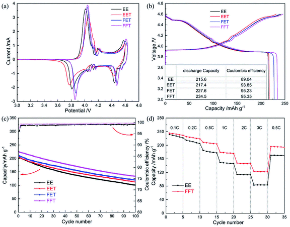 | ||
| Fig. 2 Electrochemical properties of LCO/Li half cells in various electrolytes: (a) initial CV curve; (b) initial potential profile; (c) cycle performance; (d) C-rate performance. | ||
The cycle performances of LCO/Li half cell in various electrolytes are shown in Fig. 2c. The cell in base electrolyte exhibits rapid capacity decay with relatively-low CE value upon cycling, and only half of the initial capacity is held after 100 cycles at a current density of 0.5C. The existence of fluorizated solvents increases the reversible capacity and CE over the whole cycling period. Especially, the cell in FFT demonstrate the best cyclability compared to the other counterparts. In addition, the FFT electrolyte also offers enhanced rate capability even at a rate of 3C in contrast to base electrolyte (Fig. 2d), despite of its weaker ionic conductivity. All of above results suggests that the coordination of fluorizated solvents ought to efficiently prevent the electrolyte from oxidative decomposition on the LCO cathode and restrict possible parasitic reaction between them, therefore promoting the electrochemical performance of the LCO/Li cell.
Electrochemical impedance spectroscopy (EIS) was performed to understand the discrepant cell performance from different electrolytes. As shown in Fig. 3a, the high-frequency intercept is due to ohmic resistance (Ro), including the electrolyte and electrode resistances.26 The broad depressed semicircle is related to the combination of solid-electrolyte interface (SEI) resistance formed during the charge/discharge process (Rs) and charge transfer resistance between electrode and electrolyte (Rct).27 After the three pre-cycles (Fig. 3b), the impedance response can be divided into two obscure semicircles, which corresponds to Rs and Rct, respectively. The fitted resistance data according to the corresponding equivalent circuit are shown in Table 1.
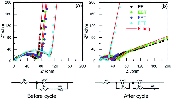 | ||
| Fig. 3 EIS plots of LCO/Li cells in various electrolytes (a) before cycle and (b) after three pre-cycles (corresponding equivalent circuit used for fitting was shown below). | ||
| Electrolyte | Before cycle | After 3rd cycles | ||||
|---|---|---|---|---|---|---|
| R0 | Rs + Rct | R0 | Rs | Rct | Rs + Rct | |
| EE | 2.00 | 56.39 | 2.16 | 41.64 | 15.92 | 57.56 |
| EET | 2.05 | 65.88 | 2.16 | 49.25 | 12.10 | 61.35 |
| FET | 2.40 | 77.78 | 2.13 | 25.60 | 8.75 | 34.35 |
| FFT | 3.73 | 109.80 | 2.92 | 12.28 | 12.43 | 24.71 |
It can been seen from the EIS data that the cell in EE exhibits increased overall resistance while other cells all reduces the value after three pre-cycles. Moreover, FET and FFT electrolyte deliver distinctly lower Rs and Rct after pre-cycling although their initial resistances are relatively higher than that of EE. These results implies that stable and favorable CEI has been formed on the LCO cycled in the two fluorizated electrolytes. In other words, the fluorizated solvents modify the cathodic surface chemistry by their synergistic effect upon cycling. This facilitates Li+ intercalation in the LCO particle, allowing for faster and more efficient charge transfer reaction.28 As for EET, it offers higher interfacial resistance than EE no matter before or after precycling, suggesting that the employment of single fluorinated ether merely leads to unsuccessful cathodic interface modification.
The compatibility of fluorizated electrolytes with MCMB anode was investigated in the MCMB/Li half cell. For CV measurement (Fig. 4a–d), a pair of clear redox peak stands for Li+ extraction/insertion in the MCMB.29 A weak reduction peak located at 1.1–1.2 V (Fig. 4b and d) should be attributed to participation of SEI construction by fluorinated ether TFEE. It has been widely reported that the reductive decomposition of fluorinated ether occured before that of conventional carbonates such as EC in virtue of lower LUMO energy level,18,30 which usually plays a key role in improving SEI property. The potential profiles of MCMB/Li half cells (Fig. 4e) demonstrate that the initial CEs in the FET and FFT are slightly lower than that in base electrolyte, probably due to the capacity loss via a higher reduction tendency of fluorizated components. But the two electrolytes all contributes to increased reversible capacity with quite stable performance over repeated cycles (Fig. 4f), revealing their excellent compatibility with MCMB anode. The EET exhibits highest initial CE (∼95.3%) and best cycle performance among several cases, suggesting that introducing single fluorinated ether in the electrolyte is already enough to build up a favorable SEI on the MCMB.
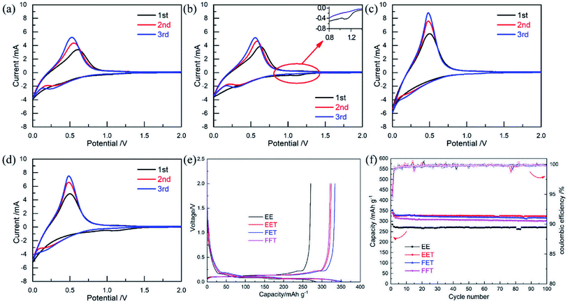 | ||
| Fig. 4 Electrochemical properties of MCMB/Li half cells in various electrolytes: CV curves for (a) EE, (b) EET, (c) FET and (d) FFT; (e) potential profile; (f) cycle performance. | ||
Finally, the superiority of designed fluorinated electrolyte was evaluated by a LCO/MCMB full cell. As shown in Fig. 5a, obviously enhanced cyclability is exhibited in FFT and FET cases at the upper voltage of 4.45 V. Especially, the cell in FFT favors a initial capacity of ∼205 mA h g−1 and capacity retention of 76% after 100 cycles, with quite stable CE and charge/discharge potential plateau (Fig. 5b), owing to the overall property improvements of the cathode, anode and electrolyte by fluorinated solvents. It is noteworthy that the EET cell is lack of notable performance difference compared to the EE cell, despite of excellent anode stability of the former (as confirmed in Fig. 4f). This reminds us that the cathodic property should be more crucial for high voltage operation of LCO/MCMB full cell than the anodic property.
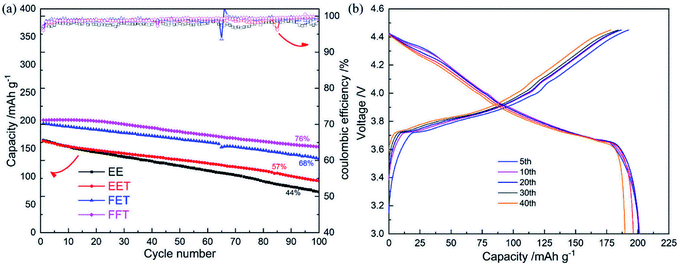 | ||
| Fig. 5 (a) Cycle performances of LCO/MCMB full cells in various electrolytes at 0.5C; (b) charge/discharge curves of LCO/MCMB full cell in FFT. | ||
3.3 Interfacial analyses on both electrodes
To elucidate the effects of regulating fluorinated solvents on the interfacial chemistry on both electrodes, the LCO and MCMB disassembled from the cycled full cell was further analysed by SEM and XPS technology, respectively. The surface morphologies of LCO cathodes cycled in various electrolytes are exhibited in Fig. 6. The fresh LCO (Fig. 6a) particle with smooth surface surrounded by large quantities of conductive carbon black is observed. After cycling in EE (Fig. 6b), some clear microcracks appear on the LCO surface, which is usually caused by the accumulated strain within the particle due to phase transition at high voltage during repeated Li+ extraction/insertion process, coupled with the decreased Li+ diffusivity and dramatic capacity fading in the deeply charged LCO.10 These microcracks is partially preserved in the LCO cycled in EET (Fig. 6c) and FET (Fig. 6d), and yet almost disappears in the case of FFT (Fig. 6e). This confirms that the stress evolution and mechanical degradation in the LCO is effectively mitigated by the cooperation of ternary fluorizated solvents.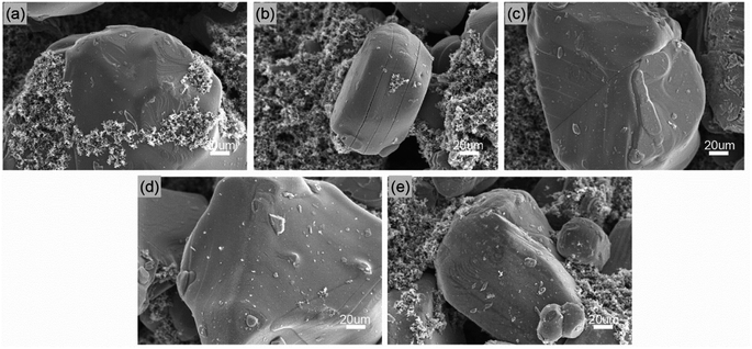 | ||
| Fig. 6 SEM images taken from the surfaces of (a) a fresh LCO, a cycled LCO in (b) EE, (c) EET, (d) FET and (e) FFT. | ||
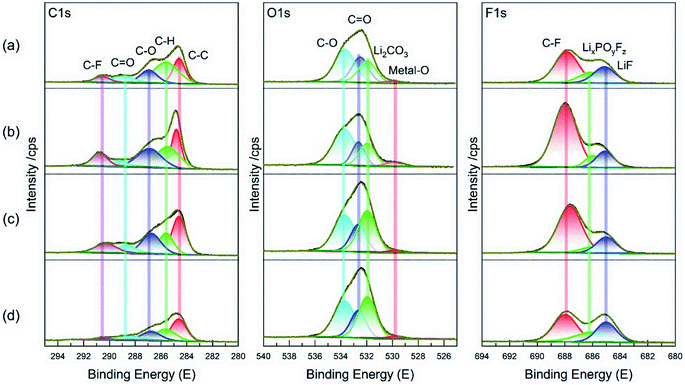
The XPS spectra measured from the cycled LCO cathode in various electrolytes were compared in Fig. 7. The C 1s spectra can be divided into five peaks, in which the existence of C–O and C![[double bond, length as m-dash]](https://www.rsc.org/images/entities/char_e001.gif) O peak mean that the cycled LCO is covered by some organic/inorganic degradation products.31 For the O 1s spectra, the Li2CO3 peak is clearly stronger in two FEC-contained electrolytes than those without it, which is considered to be mainly from FEC decomposition32 and contribute to CEI amelioration. A bit stronger intensities of metal–O peak (from LCO) and C–F peak (usually from PVDF binder)33 in the EET compared to other cases implies defective/weak protective film formed on LCO surface and hence results in high interfacial resistance confirmed in Fig. 3. Besides, the F 1s spectra demonstrates a lower LixPOyFz peak (the byproduct of LiPF6)34 in the FET and FFT than EE, suggesting the effective restraint towards electrolyte degradation. All of these results suggest that the fluorinated solvents cooperatively modify CEI on the LCO by moderate modulation of the interfacial constitution.
O peak mean that the cycled LCO is covered by some organic/inorganic degradation products.31 For the O 1s spectra, the Li2CO3 peak is clearly stronger in two FEC-contained electrolytes than those without it, which is considered to be mainly from FEC decomposition32 and contribute to CEI amelioration. A bit stronger intensities of metal–O peak (from LCO) and C–F peak (usually from PVDF binder)33 in the EET compared to other cases implies defective/weak protective film formed on LCO surface and hence results in high interfacial resistance confirmed in Fig. 3. Besides, the F 1s spectra demonstrates a lower LixPOyFz peak (the byproduct of LiPF6)34 in the FET and FFT than EE, suggesting the effective restraint towards electrolyte degradation. All of these results suggest that the fluorinated solvents cooperatively modify CEI on the LCO by moderate modulation of the interfacial constitution.
The SEM images of the cycled MCMB anode in various electrolytes are exhibited in Fig. 8. Compared to the fresh MCMB (Fig. 8a), the cycled MCMB particle in EE (Fig. 8b) is covered on some laminar cracks with loose morphology (identified by the inserted arrows). It would be the result of irreversible deposition and/or structural failure caused by repeated volume change during cycling. By contrast, the compact and dense surface is formed in several fluorizated electrolytes (Fig. 8c–e), which can prevent direct contact and side reaction between the MCMB and the electrolyte, consequently reducing the irreversible capacity loss.
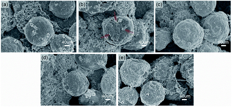 | ||
| Fig. 8 SEM images taken from the surfaces of (a) a fresh MCMB, a cycled MCMB in (b) EE, (c) EET, (d) FET and (e) FFT. | ||
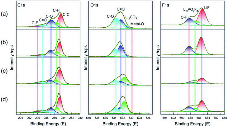
The XPS spectra obtained from the cycled MCMB in various electrolytes were further compared in Fig. 9. The C 1s spectrum has no considerable contrast in these electrolyte cases. However, the Li2CO3 component dominates the O 1s spectrum when the MCMB was cycled in two FEC-contained electrolytes, similar to the XPS result of LCO cathode in Fig. 7. It reveals that this fluorizated carbonate simultaneously contributes to the surface chemistry on both electrodes. Also, the F 1s spectra indicates that the allocated LixPOyFz and LiF peaks are greatly reduced for the cycled MCMB in FET and FFT compared to that in the EE electrolyte without fluorizated solvent. As previously mentioned, these components are usually originated from the decomposition of LiPF6 and always increase the interfacial resistance. The decreases in their contents suggest the SEI construction on the MCMB has been synergistically ameliorated by the fluorizated solvents as well. However, it needs to be emphasized that total F concentration is relatively higher in the FFT compared to that in FET. This is ascribed to the fact that a resultant SEI in the perfluorinated electrolyte is inevitably highly fluorinated in the composition because all of the fluorinated solvents may participate in surface passivation by reductive decomposition.20,35 As for the EET, the high intensity of LiF peak can be attributed to decomposition of Li salt and fluorinated ether together. Compared to EE, the decreased LixPOyFz but similar LiF peak suggest that the fluorinated ether in EET participates in SEI formation by supplementing the LiF species, which is eventually beneficial to stable surface passivation on the MCMB. However, this does not provide valid assistance for the improvement of full cell performance because the restricting factor is mainly located at the cathode side, as discussed above.
4. Conclusions
In summary, distinct influences of fluorizated solvent composition on the electrolyte property, two-sided interface constitution and electrochemical performance of LCO/MCMB cell were demonstrated in this study. Although the co-existence of fluorizated carbonate and fluorizated ether causes the decrease in ionic conductivity, they cooperately offer preferable surface passivation on the LCO cathode and the MCMB anode, as well as enhanced oxidation durability of the electrolyte. Remarkably, the LCO/MCMB full cell in the perfluorinated electrolyte FFT holds superior overall performance at the limited voltage of 4.45 V compared to other contrastive cases, delivering a specific capacity of ∼205 mA h g−1 and capacity retention of ∼76% after 100 cycles. This study well exhibits the application prospect of fluorizated electrolytes employed for high-voltage LCO cathode and will be conducive to promote the further development of high-energy-density LIBs.Conflicts of interest
There are no conflicts to declare.Acknowledgements
This work was supported by the National Natural Science Foundation of China (No. 51604221) and the Key Innovation Team of Shaanxi Province (2014KCT-04).The authors thank Shiyanjia Lab for the XPS measurement.References
- H. Liu, H. Du, W. Zhao, X. Qiang, B. Zheng, Y. Li and B. Cao, Energy Storage Mater., 2021, 40, 490–498 CrossRef
.
- Z. Hou, H. Lu, Y. Li, L. Yang and Y. Gao, Front. Mater, 2021, 8, 647229 CrossRef
.
- X. Liu, R. Rao, J. Shi, J. He, Y. Zhao, J. Liu and H. Du, J. Alloys Compd., 2021, 875, 159999 CrossRef CAS
.
- K. Gao, X. Guo, B. Zheng, J. Wang and L. Wang, Mater. Today Chem., 2021, 20, 100458 CrossRef CAS
.
- H. Lu, Y. Zhu, Y. Yuan, L. He, B. Zheng, X. Zheng, C. Liu and H. Du, J. Mater. Sci.: Mater. Electron., 2021, 32, 5898–5906 CrossRef CAS
.
- J. Shi, Y. Zhao, R. Dong, W. Tian and X. Liu, J. Alloys Compd., 2021, 889, 161720 CrossRef
.
- J. B. Goodenough, Nat. Electron., 2018, 1, 204 CrossRef
.
- J.-N. Zhang, Q. Li, C. Ouyang, X. Yu, M. Ge, X. Huang, E. Hu, C. Ma, S. Li, R. Xiao, W. Yang, Y. Chu, Y. Liu, H. Yu, X.-Q. Yang, X. Huang, L. Chen and H. Li, Nat. Energy, 2019, 4, 594–603 CrossRef CAS
.
- J. Ge, H. Liang, M. Zhou, C. Zhao, Z. Zheng, Y. Yan, L. Zhao and K. Tang, ChemistrySelect, 2019, 4, 9959–9965 CrossRef CAS
.
- Q. Liu, X. Su, D. Lei, Y. Qin, J. Wen, F. Guo, Y. A. Wu, Y. Rong, R. Kou, X. Xiao, F. Aguesse, J. Bareño, Y. Ren, W. Lu and Y. Li, Nat. Energy, 2018, 3, 936–943 CrossRef CAS
.
- X. Zuo, C. Fan, X. Xiao, J. Liu and J. Nan, J. Power Sources, 2012, 219, 94–99 CrossRef CAS
.
- X. Zheng, Y. Liao, Z. Zhang, J. Zhu, F. Ren, H. He, Y. Xiang, Y. Zheng and Y. Yang, J. Energy Chem., 2020, 42, 62–70 CrossRef
.
- C.-C. Su, M. He, R. Amine, Z. Chen, R. Sahore, N. Dietz Rago and K. Amine, Energy Storage Mater., 2019, 17, 284–292 CrossRef
.
- C. V. Amanchukwu, Z. Yu, X. Kong, J. Qin, Y. Cui and Z. Bao, J. Am. Chem. Soc., 2020, 142, 7393–7403 CrossRef CAS PubMed
.
- E. Markevich, G. Salitra and D. Aurbach, ACS Energy Lett., 2017, 2, 1337–1345 CrossRef CAS
.
- L. Xia, S. Lee, Y. Jiang, Y. Xia, G. Z. Chen and Z. Liu, ACS Omega, 2017, 2, 8741–8750 CrossRef CAS PubMed
.
- J. Liu, L. Zhou, W. Yu and A. Yu, J. Alloys Compd., 2020, 812, 152064 CrossRef CAS
.
- C.-K. Kim, K. Kim, K. Shin, J.-J. Woo, S. Kim, S. Y. Hong and N.-S. Choi, ACS Appl. Mater. Interfaces, 2017, 9, 44161–44172 CrossRef CAS PubMed
.
- L. Xia, S. Lee, Y. Jiang, S. Li, Z. Liu, L. Yu, D. Hu, S. Wang, Y. Liu and G. Z. Chen, ChemElectroChem, 2019, 6, 3747–3755 CrossRef CAS
.
- X. Fan, L. Chen, O. Borodin, X. Ji, J. Chen, S. Hou, T. Deng, J. Zheng, C. Yang, S.-C. Liou, K. Amine, K. Xu and C. Wang, Nat. Nanotechnol., 2018, 13, 715–722 CrossRef CAS PubMed
.
- L. Chen, X. Fan, E. Hu, X. Ji, J. Chen, S. Hou, T. Deng, J. Li, D. Su, X. Yang and C. Wang, Chem, 2019, 5, 896–912 CAS
.
- H.-Q. Pham, H.-Y. Lee, E.-H. Hwang, Y.-G. Kwon and S.-W. Song, J. Power Sources, 2018, 404, 13–19 CrossRef CAS
.
- C.-C. Su, M. He, R. Amine, T. Rojas, L. Cheng, A. T. Ngo and K. Amine, Energy Environ. Sci., 2019, 12, 1249–1254 RSC
.
- C. Wang, X. Zuo, M. Zhao, X. Xiao, L. Yu and J. Nan, J. Power Sources, 2016, 307, 772–781 CrossRef CAS
.
- C. Pang, G. Xu, W. An, G. Ding, X. Liu, J. Chai, J. Ma, H. Liu and G. Cui, Energy Technol., 2017, 5, 1979–1989 CrossRef CAS
.
- H. Lu, L. He, X. Li, W. Zhang, J. Che, X. Liu, Z. Hou, H. Du and Y. Qu, J. Mater. Sci.: Mater. Electron., 2019, 30, 13933–13938 CrossRef CAS
.
- Y. Yuan, D. Zheng, H. Lu, Y. Zhu, Z. Li, F. Qin and K. Zhang, Appl. Surf. Sci., 2020, 533, 147490 CrossRef CAS
.
- H. Lu, L. He, Y. Yuan, Y. Zhu, B. Zheng, X. Zheng, C. Liu and H. Du, J. Electrochem. Soc., 2020, 167, 120534 CrossRef CAS
.
- C. Wang, S. Tang, X. Zuo, X. Xiao, J. Liu and J. Nan, J. Electrochem. Soc., 2015, 162, A1997–A2003 CrossRef CAS
.
- Y. Lee, T. K. Lee, S. Kim, J. Lee, Y. Ahn, K. Kim, H. Ma, G. Park, S.-M. Lee, S. K. Kwak and N.-S. Choi, Nano Energy, 2020, 67, 104309 CrossRef CAS
.
- L. Wang, Y. Ma, Y. Qu, X. Cheng, P. Zuo, C. Du, Y. Gao and G. Yin, Electrochim. Acta, 2016, 191, 8–15 CrossRef CAS
.
- G. Yan, X. Li, Z. Wang, H. Guo and J. Wang, J. Phys. Chem. C, 2014, 118, 6586–6593 CrossRef CAS
.
- Y. Luo, T. Lu, Y. Zhang, L. Yan, J. Xie and S. S. Mao, J. Power Sources, 2016, 323, 134–141 CrossRef CAS
.
- L. Xia, B. Tang, L. Yao, K. Wang, A. Cheris, Y. Pan, S. Lee, Y. Xia, G. Z. Chen and Z. Liu, ChemistrySelect, 2017, 2, 7353–7361 CrossRef CAS
.
- T. Li, X.-Q. Zhang, P. Shi and Q. Zhang, Joule, 2019, 3, 2647–2661 CrossRef CAS
.
| This journal is © The Royal Society of Chemistry 2021 |

