 Open Access Article
Interpenetrating network nanoarchitectonics of antifouling poly(vinylidene fluoride) membranes for oil–water separation
Yongqiang Guoac,
Chao Liu *ab,
Wei Xub,
Guangli Liub,
Ke Xiao
 *a and
Hua-Zhang Zhao*b
aWater Science and Environmental Engineering Research Center, College of Chemical and Environmental Engineering, Shenzhen University, Shenzhen 518060, PR China. E-mail: liuchao@szu.edu.cn; xiaoke@szu.edu.cn
bThe Key Laboratory of Water and Sediment Sciences, Ministry of Education, College of Environmental Sciences and Engineering, Peking University, Beijing 100871, PR China. E-mail: zhaohuazhang@pku.edu.cn
cJiangsu Hengrui Medicine Co.,Ltd, Lianyungang 222000, PR China
First published on 27th September 2021
Abstract
Poly(vinylidene fluoride) (PVDF) membranes are a commonly used cheap material and have been widely used in wastewater treatment. In this study, a simple strategy was proposed to construct PVDF-g-PEG membranes with an interpenetrating network structure by simulating plant roots for the treatment of oil/water emulsion. Meanwhile, the hydrophilicity, antifouling, and mechanical properties of the membrane were improved. A series of chemical and physical characterization methods were used to verify the successful formation of a PVDF-g-PEG layer on the membrane surface. The effects of graft modifier content on the crystallization behavior, microstructure, and membrane permeability were studied. When the optimized membrane (m-PVDF-2) was applied to the treatment of oily wastewater, its separation performance was significantly better than that of the blank PVDF membrane, and the oil removal rate was over 99.3%. BSA and oil contamination were nearly reversible, and excellent oil resistance to high-viscosity oil was also observed. The method reported in this article is a one-step, simple method for constructing hydrophilic and oil-resistant PVDF membranes without any intermediate additives and harmful or costly catalysts. They can be used as an ideal material for preparing efficient oil–water separation membranes.
1. Introduction
The increase in industrial oily wastewater discharge and the frequent occurrence of petroleum leakage accidents have made the pollution of oily wastewater one of the main sources of harm to the ecological environment and human health.1,2 The efficient and pollution-free separation of oily wastewater is a widely recognized strategy for sustainable development.3 Compared with traditional separation methods, such as oxidation, biological, and chemical flocculation methods, membrane filtration separation technology has the advantages of simple operation, no phase change, larger separation coefficient, energy saving, high efficiency, excellent economic benefits, and no secondary pollution.4–6 It is an effective way to solve the problem of oily wastewater. It has important applications in chemical, petrochemical, food industry, pharmaceutical industry, and biotechnology environmental engineering.7–9 Poly(vinylidene fluoride) (PVDF) membrane has excellent chemical stability, thermal stability, and enough mechanical strength.10 It is an ideal polymer membrane material and is used as an excellent choice for oily wastewater treatment.The surface of the PVDF membrane is mainly composed of C–F bonds. Thus, its surface is chemically inert and has difficulty forming hydrogen bonds with water molecules, which is reflected in low hydrophilicity and surface energy.11 At the same time, the organic foulants are easily adsorbed on the surface and pores of PVDF membrane due to the strong hydrophobicity of the PVDF membrane in the water treatment process.12,13 This phenomenon increases the transmission resistance and restricts its further application. Nowadays, many studies have proven that membrane fouling decreases as the hydrophilicity of the membrane increases. Some hydrophilic modification methods, such as hybrid, coating, plasma modification, and chemical modification methods, have been widely reported.10,14–16 However, these modification methods are often accompanied by some unavoidable shortcomings. For example, the membrane produced by the ordinary hybrid method has a short service life.3 The surface coating made by coating method is easy to be washed off and even causes secondary pollution because it only depends on physical adsorption.17 The chemical modification method is often complicated in operation and has great pollution in production.18 Thus, it is unsuitable for large-scale industrial production.
Gamma radiation has high energy and strong penetrability.19 The highly active particles can act on the irradiated material and stimulate the active molecules or ions.20 As a result, some reactions are difficult to be conducted by general thermochemical methods. When the γ-ray interacts with the irradiated material to generate energy transfer, ion pairs and excited molecules proportional to the absorbed dose will be produced, and the yield of both is roughly the same. In general, ion pairs and excitation molecules undergo a process of forming free radicals, but they may also directly combine to form stable products. Radiation can induce cleavage at multiple sites, among which C–C, C–H, and C–F bonds can be broken under the action of gamma radiation.21,22 Thus, the high-energy γ-ray irradiation modification can change the chemical composition of the film surface, initiate surface grafting reaction, and realize the design of the molecular structure of the membrane surface.23 At the same time, the γ-ray irradiation treatment process is simple and has easy to control operation process and stable and reliable product performance. The irradiation treatment also has short treatment time, high efficiency and reduced working cycle and is suitable for mass production and industrialization.
In this study, a hydrophilic and antifouling PVDF membrane was prepared by γ-ray irradiation inducing polyethylene glycol (PEG) for oily wastewater treatment. The elemental composition, crystallization behavior, microstructure (morphology, porosity, charge, roughness, and hydrophobicity), and other physical and chemical properties of the prepared membrane were characterized extensively to understand the interaction mechanism of PEG modification of PVDF. The pure water flux, oil/water emulsion filtration performance, and antifouling properties were evaluated. These membranes were subjected to high-viscosity oil immersion test to evaluate their anti-oil pollution performance. In addition, the mechanical properties of PVDF membrane before and after PEG modification were investigated in detail. This research aims to explore a simple and scalable method to provide a new idea for the preparation and modification of novel oil–water separation membranes.
2. Experimental
2.1. Materials
PVDF (Mw ∼ 1![[thin space (1/6-em)]](https://www.rsc.org/images/entities/char_2009.gif) 000
000![[thin space (1/6-em)]](https://www.rsc.org/images/entities/char_2009.gif) 000), bovine serum albumin (BSA, purity ≥98%), and sodium dodecyl sulfate (SDS) were acquired from Beijing InnoChem Science & Technology Co., Ltd. (China). PEG (Mw = 2000) was purchased from Shanghai Yuanye Bio-Technology Co., Ltd. (China). N,N-Dimethylformamide (DMF, purity ≥99.5%) was purchased from West Long Chemical Co., Ltd. (China). Phosphate buffer saline (PBS, pH 7.3–7.5) was provided by Shanghai Aladdin Bio-Chem Technology Co., Ltd. (China). Lubricating oil (10W-40) and soybean oil were purchased from Shell Group of Companies (Holland) and Jiusan Oils and Grains Industries Group Co., Ltd. (China), respectively. Other reagents and materials such as potassium bromide, potassium chloride, and ethyl alcohol were supplied by Kermel Chemical Reagent Co., Ltd. (China). Unless otherwise specified, all reagents and materials were used directly without further processing.
000), bovine serum albumin (BSA, purity ≥98%), and sodium dodecyl sulfate (SDS) were acquired from Beijing InnoChem Science & Technology Co., Ltd. (China). PEG (Mw = 2000) was purchased from Shanghai Yuanye Bio-Technology Co., Ltd. (China). N,N-Dimethylformamide (DMF, purity ≥99.5%) was purchased from West Long Chemical Co., Ltd. (China). Phosphate buffer saline (PBS, pH 7.3–7.5) was provided by Shanghai Aladdin Bio-Chem Technology Co., Ltd. (China). Lubricating oil (10W-40) and soybean oil were purchased from Shell Group of Companies (Holland) and Jiusan Oils and Grains Industries Group Co., Ltd. (China), respectively. Other reagents and materials such as potassium bromide, potassium chloride, and ethyl alcohol were supplied by Kermel Chemical Reagent Co., Ltd. (China). Unless otherwise specified, all reagents and materials were used directly without further processing.
2.2. Preparation of PVDF-g-PEG membrane
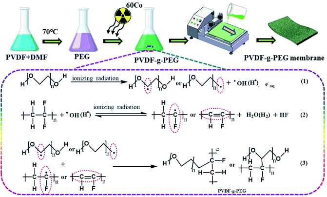
Various PVDF modified membranes were prepared through non-solvent-induced phase separation method. A total of 20 wt% PVDF and (0, 2, 4, 6, 8) wt% PEG were fully dissolved in DMF at 70 °C and left to stand for 12 h to remove bubbles. The solution was poured into the glass irradiation tube and sealed. Gamma-ray irradiation was conducted under normal temperature and pressure using industrial equipment with 60 Co source (cobalt source from Russia, intensity 3.7 × 10¹⁵ Bq), the dose rate was 6 kGyh−1, and the total radiation dose was 15 kGy. After the treatment, the irradiation system was placed in a fume hood at room temperature for 24 h to fully complete the graft activation reaction and obtain the PVDF-g-PEG system casting solution. After the casting solution was preheated at 60 °C for 1 h, the casting solution was poured onto a glass plate. A membrane of a certain thickness (200 μm) was scraped out with a spatula, and then, the glass plate was placed in 60 °C deionized (DI) water for phase transfer. The membrane was soaked in DI water for at least 24 h to complete the migration of hydrophilic groups to the membrane surface. The possible graft mechanism and preparation process of the PVDF-g-PEG membrane is shown in Fig. 1. PVDF membranes prepared with different PEG concentrations were called PVDF, m-PVDF-1, m-PVDF-2, m-PVDF-3, and m-PVDF-4.2.3. Membrane characterization
Fourier transform infrared (FTIR) Spectrometer (model: AVATAR360, USA) was used to characterize the functional group and chemical constitution of the PVDF membrane. The scanning range was from 3600 cm−1 to 600 cm−1. The surface elemental composition was determined using X-ray photoelectron spectrometer (XPS) (model: AXIS Supra, UK). Raman spectra (model: inVia-Reflex, UK) were obtained to distinguish different crystalline phase characteristic bands of the prepared PVDF membranes. A 532 nm laser with a step length of 0.1 μm was used to analyze the peak-to-height ratio (799/840 cm−1) on the surface of the 5 μm × 5 μm. The surface roughness and morphology were estimated by atomic force microscopy (AFM) (model: Bruker Icon030118, German). The test area was 10 μm × 10 μm and scanning range frequency was 5 Hz at least three times. The scanning electron microscope (SEM) (model: S-4800, Japan) was used to further evaluate the top-view and cross-section morphology of the preparative membranes. The hydrophilicity and ζ-potential of the surface were investigated using the contact angle measuring instrument (model: SL200KB, China) and the solid surface zeta potentiometer (model: Surpass, Austria), respectively. The membrane was weighed with a known area in a moisture-absorbing state and immediately dried in the oven.24 The porosity was calculated as follows:
 | (1) |
2.4. Evaluation of filtration and separation performance
A stirred tank ultrafiltration unit (model: Millipore 8200, USA, effective filtration area of 28.7 cm2) was used for pure water flux test. The preparative membranes were placed at the bottom of the stirred cell and filled with DI water. The device was pressurized with compressed nitrogen to maintain a constant transmembrane pressure (TMP) gradient (0.15 MPa). Subsequently, the applied pressure on the preparative membrane surface was adjusted to 0.1 MPa. When the pressure value and temperature remained unchanged, the water output was stable, and the water flux of the preparative membrane in a certain period of time (1 h) was determined. The pure water flux (Jw) was calculated as follows:
 | (2) |
Using 0.1 wt% BSA aqueous solution as the filtrate model, the experimental device was the same as the water flux testing unit. The rejection rate of PVDF membrane for protein macromolecules was tested at room temperature with TMP of 0.1 MPa for 1 h. A total of 1 g of BSA was dissolved in 1 L PBS buffer solution (pH 7.3–7.5) to obtain a 0.1 wt% BSA solution. The rejection rate RB(%) can be calculated as follows:
| RB (%) = (C1 − C2)/C1 × 100 | (3) |
Oil/water emulsion with surfactant stability was prepared through adding 10 mg SDS in 495 mL water and then adding 5 mL soybean oil and stirring at high intensity for 30 min. The permeation efficiency of PVDF membrane for oil/water emulsion was evaluated by the same method as that of pure water and BSA solution. The concentration of soybean oil was determined by analyzing the chemical oxygen demand of the emulsion (model: 5B-3C(V8), China). After oil-in-water emulsion filtration, the membrane surface was thoroughly rinsed with 500 mL of DI water, and the pure water and the emulsion were filtered under the same conditions for 1 h. The process of rinsing with DI water, 1 h of pure water filtration, and 1 h of oil-in-water emulsion separation was referred to as a “washing–filtering cycle”.
2.5. Evaluation of antifouling property
Using 0.1 wt% BSA aqueous solution as a fouling model system, the antifouling properties of the membrane were estimated through three cycles of “washing–filtering cycle” similar to oil/water emulsion. The initial water flux (Jw1) was obtained by measuring pure water for 30 min, and real-time water flux was recorded every 5 min. Next, the foulant volume flux (Jw2) of the model system for a period of 1 h was tested. Finally, the model foulants were all emptied, the membrane was flushed with DI water, and the water flux (Jw3) at the same pressure for 30 min was retested. The flux recovery ratio (FRR), total flux decline ratio (FDR), and irreversible FDR (DRir) were calculated to appraise the antifouling performance of the membrane. Their calculation formula was as follows:
 | (4) |
 | (5) |
 | (6) |
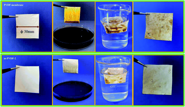
The membrane fouling test was conducted with high-viscosity lubricating oil as a model to further compare the antifouling properties of the PEG-modified PVDF membrane. The test procedure was as follows: the wet membrane was soaked in pure lubricating oil for 60 s, the membrane was collected and soaked in water, the membrane was gently rinsed with 100 mL DI water, and the pollution of the membrane surface was directly compared.
2.6. Evaluation of the mechanical strength
The effect of PEG-modification process on the mechanical performances of PVDF membrane was investigated by means of electron tensile testing machine (model: Instron-5969, USA). The PVDF membranes were cut into five strips with a width (20 mm × 100 mm) for the mechanical testing, and each sample was tested for five times to obtain the average result. The instrument setting parameters of the tensile test were the tensile test speed of 200 mm min−1, the sampling frequency of 2000 Hz, the initial tensile value of 100 cN, and the clamping distance of 20 mm. Notably, the fixture and membrane should be kept vertical during the testing process. Sandpaper can be introduced into the fixture to prevent slipping during the test and affecting the test accuracy.3. Results and discussion
3.1. Membrane surface characterization
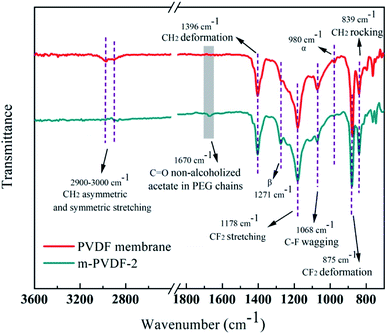
The surface functional groups and chemical structure of the prepared membranes were systematically analyzed through ATR-FTIR and XPS. The ATR-FTIR spectra of the initial PDVF membrane and the PEG-modified membrane are shown in Fig. 2. The representative peaks at 1178 and 875 cm−1 are considered to be the chemical structure of –CF2 stretching and deformation.25 The typical peaks at 3022 and 2978 cm−1 correspond to the asymmetric and symmetric stretching of –CH2, respectively.26 The peaks at 1396 and 839 cm−1 are related to the deformation and rocking of –CH2. Notably, a new peak at 1670 cm−1 is attributed to non-alcoholized acetate in PEG chains, and the strength of C–F wagging peak at 1068 cm−1 is weakened.16,27 In addition, the peaks at 1271 and 980 cm−1 are attributed to the β and α crystal phases of PVDF.25 With the introduction of PEG, the β-peak intensity gradually increases while the α-peak decreases. In general, PEG and PVDF are sensitive under the action of high-energy radiation, and free radicals are easily formed on the carbon skeleton through homolysis reaction of CH2 and α-H. Reactive radicals produced on the polymer skeleton can initiate crosslinking reactions with various macromolecules or functional monomers. Therefore, the random collision coupling between the PEG and PVDF free radicals enables the PEG chain to anchor on the membrane surface. The XPS spectrum of the preparative membranes is shown in Fig. 3a. The intensities of F 1s for the PEG-modified membrane are significantly lower than that of the initial PVDF membrane. Table 1 shows that the carbon and oxygen contents of m-PVDF (1–4) are observably high. The oxygen content comes from the additive PEG. Increasing the concentration of oxygen atoms can enrich the membrane surface with more polar groups, which will cause the hydrophilicity of the membrane surface. This condition will affect the membrane antifouling and other properties. Fig. 3b also demonstrates the C 1s core-level spectra of the initial PVDF membrane. The binding energies of the two main peaks are 289.5 and 285.0 eV, and the two peaks are attributed to CF2 and CH2, respectively.1 Two new peaks at 283.1 and 286.1 eV appear at the C 1s core-level spectra of the PVDF-g-PEG membrane, and the two peaks correspond to C–H and C–OH/C–H, respectively. The results of XPS and ATR-FTIR spectra confirm that PEG is successfully grafted onto the membrane surface through covalent bonds.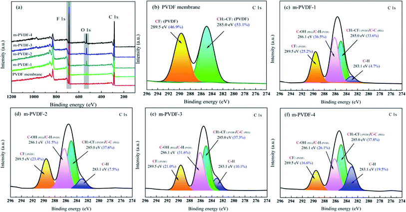 | ||
| Fig. 3 Characterization of the blank PVDF and PVDF-g-PEG membranes. (a) XPS wide-scan and (b–f) C 1s core-level spectra. | ||
| Membrane sample | Atomic percent (%) | Atomic ratio | |||
|---|---|---|---|---|---|
| C | O | F | F/C | O/C | |
| PVDF | 53.30 | 0.61 | 46.09 | 0.87 | 0.01 |
| m-PVDF-1 | 61.94 | 10.22 | 27.84 | 0.45 | 0.16 |
| m-PVDF-2 | 63.55 | 11.12 | 25.33 | 0.40 | 0.17 |
| m-PVDF-3 | 64.87 | 12.47 | 22.66 | 0.35 | 0.19 |
| m-PVDF-4 | 65.06 | 14.16 | 20.78 | 0.32 | 0.22 |
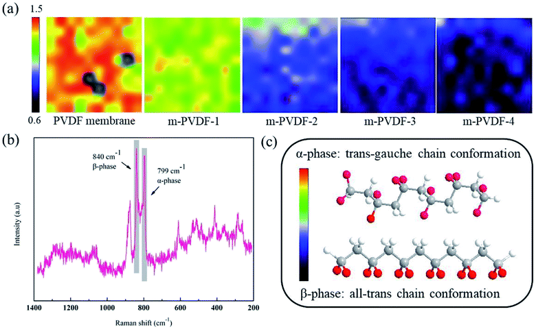
Raman spectrum was used to further analyze the chemical structure of the membrane surface. Two broad bands are observed at 799 and 840 cm−1, and they are due to the α and β crystalline phases of PVDF (Fig. 4b). Fig. 4c depicts the two most common and stable conformations of PVDF: all-trans chain conformation (β-phase) and trans–gauche chain conformation (α-phase).28 The β-phase molecules are arranged in an all-trans chain conformation, and the dipoles point in the same direction and are highly polar.29 The dipoles in the α-phase are arranged in a way of internal compensation attributed to the accumulation of antiparallel chains and are generally non-polar. The Raman mapping spectrum of the peak height ratio (799/840 cm−1) intuitively provides an assessment of the PVDF crystal phase distribution. With the increase in the concentration of grafting agent PEG, the PVDF crystal form will gradually transition from α-phase to β-phase. The polarity of C–F is the main cause of the hydrophobicity of the PVDF membrane surface. During the phase separation process, the C–F points inward due to the hydrophobicity, and this condition greatly improves the hydrophilicity of the membrane surface.28 This phenomenon once again verifies the changing trend of α and β crystal phases in ATR-FTIR spectra characterization, and the increase in hydrophilicity of the membrane surface is also proven in subsequent experiments.
The surface morphology of the prepared membrane was observed through the FE-SEM images of the surface and cross-section, as shown in Fig. 5. As observed, the number of pores in the blank PVDF membrane is less, but the number of pores in the PEG-modified membrane enhances as the content of modifier (PEG) improves. The cross-section morphology of the prepared membranes shows typical asymmetrical structure, with spongy pores in bottom layer, finger-like macropores, and dense surface layer.13 As the content of modifier increases, the asymmetry of the PEG-modified membrane also increases. This result can be due to that the presence of hydrophilic PEG polymers enhances the diffusion rate of water and organic solvents, which leads to rapid solidification of the membrane and larger pore channels. Meanwhile, the introduction of PEG polymer improves the viscosity of the casting solution, prevents the diffusion of water and organic solvents in the membrane, decreases the speed of phase conversion, and increases the number and size of finger-like pores. Specific porosity data are shown in Fig. 6c. The size and distribution of pores on the membrane surface and the cross-section morphology have a decisive effect on the water flux and antifouling property. The larger and more pores lead to a higher water flux during the filtration process.30 AFM, as a complementary technology to FE-SEM, was also used to characterize the structure and roughness of the 3D image of the membrane surface.31,32 After gamma ray irradiation, irregular masses composed of PVDF-g-PEG appear on the modified membrane surface, and this condition makes the modified membrane more uneven. The surface roughness Rq, Ra, and Rmax all show an upward trend with the increase in PEG content, as summarized in Table 2. Increasing the roughness usually enhances the effective permeation area of the membrane and increases the flux.
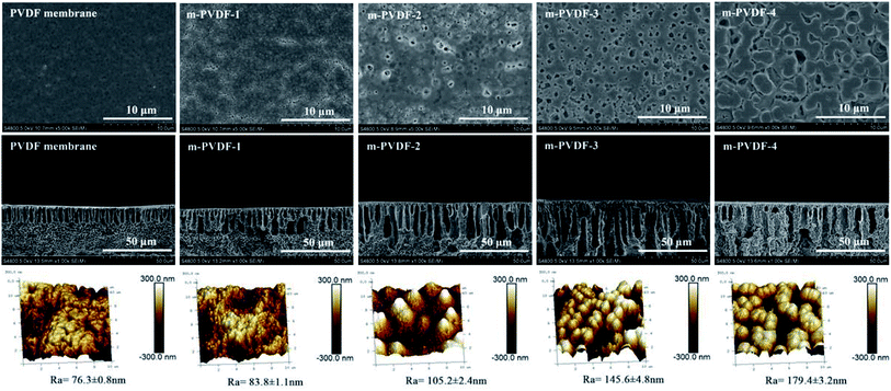 | ||
| Fig. 5 Morphology characterization of blank PVDF membrane and PVDF-g-PEG membranes. Surface SEM images (top), cross-section SEM images (middle), AFM 3D images, and roughness (bottom). | ||
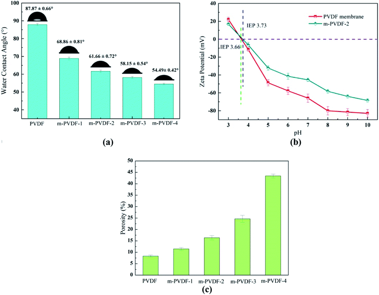 | ||
| Fig. 6 Effect of PEG modification on membrane surface properties. (a) Water contact angles, (b) surface ζ-potential over a pH range, (c) porosity of the membrane. | ||
| Membrane | Contact anglea (°) | Surface energy (mJ m−2) | Adhesion work (mN m−1) | Surface roughness (nm) | |||||
|---|---|---|---|---|---|---|---|---|---|
| Initial state | 30 s | 60 s | 90 s | Ra | Rq | Rmax | |||
| a The error in contact angle measurement is no more than 1°. | |||||||||
| PVDF | 87.87 | 84.23 | 79.44 | 76.61 | 30.56 | 75.51 | 76.3 | 96.8 | 615 |
| m-PVDF-1 | 68.86 | 58.44 | 51.55 | 46.35 | 42.2 | 99.06 | 83.8 | 104.9 | 750 |
| m-PVDF-2 | 61.66 | 50.20 | 42.98 | 38.24 | 46.98 | 107.62 | 105.2 | 133.2 | 761 |
| m-PVDF-3 | 58.15 | 46.69 | 36.75 | 31.16 | 48.95 | 111.22 | 145.6 | 185.7 | 1232 |
| m-PVDF-4 | 54.49 | 40.40 | 31.77 | 20.55 | 51.14 | 115.09 | 179.4 | 238.9 | 1531 |
3.2. Membrane surface performance
The hydrophilicity of the surface plays a vital role in the antifouling property and permeability of the membrane.33 The test results of the static water contact angle (WCA) are summarized in Fig. 6a. As the load of PEG in the membrane improves, the WCA decreases, and the hydrophilicity enhances significantly. WCA decreases from 87.87° (PVDF) to 54.49° (m-PVDF-4). This result is due to that pure PVDF membrane has the highest WCA (87.87°) because of the hydrophobicity of the C–F bond. The enhanced hydrophilicity can be attributed to the grafting of PEG, and the hydrophilic polymers preferentially migrate to the water–polymer interface during phase transformation. The roughness of the PEG-modified membrane also gradually increases with the loading of PEG in the membrane. Therefore, the surface geometry (roughness and crystal form) and chemical composition of the modified membrane surface have a synergistic effect on the surface hydrophilicity. Table 2 depicts the test results of adhesion work, dynamic WCA, and surface energy for further illustrating the hydrophilicity. The increase in adhesion work and surface energy once again verifies the enhancement in polarity and hydrophilicity on the membrane surface. The elevated hydrophilicity is expected to decrease the fouling deposition caused by the adsorption of hydrophobic pollutants and is also beneficial the infiltration of water molecules through the membrane. The membrane surface changes after PEG modification were further investigated by measuring the ζ-potential. Fig. 6b demonstrates the increase in the isoelectric point (IEP) value of m-PVDF-2 membrane to prove successful graft and modification on the membrane surface. When pH is 7.0, the ζ-potential values of PVDF and m-PVDF-2 membrane are −65.8 ± 4.5 and −45.4 ± 1.9 mV, respectively. Compared with PVDF membrane surface, the m-PVDF-2 membrane surface has a higher positive charge, which may be related to the grafted neutral PEG polymer.34 The reason for this decrease is that PEG is a neutral charge polymer, and the neutral charge coating hinders the protonation of amines and the decomposition of phenolic hydroxyl groups to a certain extent. This surface potential change will influence the electrostatic interaction on the membrane surface and will inevitably affect the separation performance of the membrane.3.3. Membrane filtration and antifouling properties
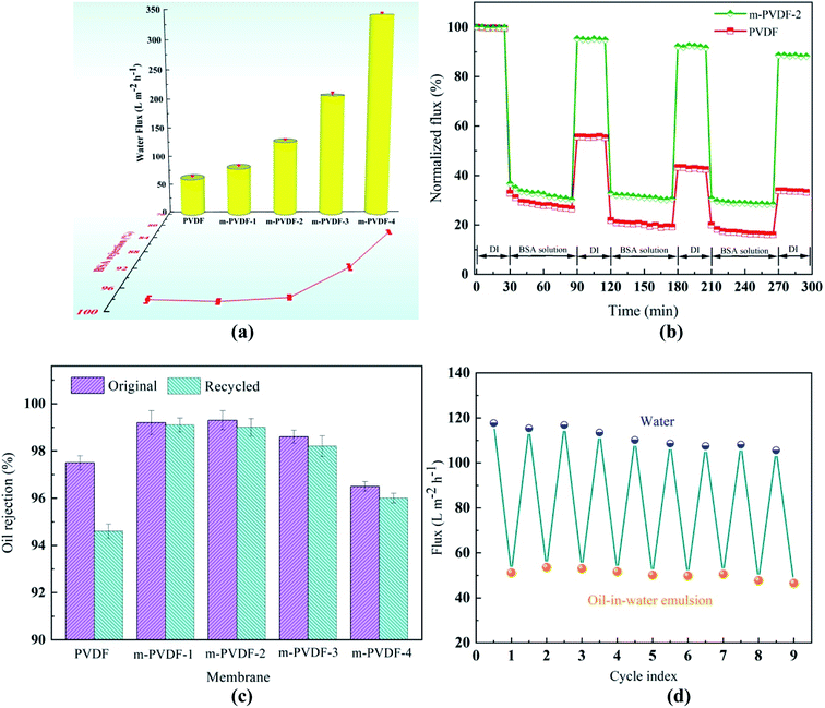
The BSA retention and pure water flux of different prepared membranes were measured at 0.1 MPa, and the results are shown in Fig. 7a. The water flux of the blank PVDF membrane is 62.6 LMH, while the flux of m-PVDF-4 increases sharply to 342.8 LMH. For the PEG-modified membrane, the hydrophilic modified layer has a certain promoting effect on the water flux of the membrane.35 After the introduction of PEG, the surface roughness and porosity of the membrane are increased. Enlarged pores and filtration area can help more water molecules pass through the membrane surface to further enhance water flux.36 Therefore, the variation of water flux is the result of a combination of many factors. Fig. 7a also shows that the BSA retention performance of m-PVDF-1 and m-PVDF-2 has no obvious effect. The reason is that, although the porosity and pore size of the membrane are increased, the hydrophilicity of the membrane surface is also improved, which enhances the ability of water to pass through the membrane and hinders the passage of macromolecules to a certain extent. When the concentration of PEG increases to 6.0 wt%, agglomeration pore formation may occur in the PEG modified membrane, and the porosity and pore size of the membrane enhance significantly. Moreover, the retention property of the membrane tends to decline. The loading of modifier can be controlled by adjusting the PEG concentration to balance penetration and retention. Thus, the m-PVDF-2 is considered to be a modified membrane with the best water flux and BSA retention performance in this study.The 0.1 wt% BSA aqueous solution was used as foulant to estimate the antifouling performance of the membrane. Fig. 7b shows the normalized volume flux as a function of time. When the BSA solution is added, the volume flux drops sharply. This decrease is due to the deposition and adsorption of foulants on the surface. After three cycles, the FDR of the blank PVDF membrane reaches 84.0%, and the FRR only recovers to 33.8% after cleaning. The reason is that the blank PVDF membrane has strong hydrophobicity, and the foulants are easy to adsorb on the membrane surface and cause the pore blockage of the membrane. By contrast, the DRir of the m-PVDF-2 is not lower than 20%, and the FRR still reaches 88.6%. This result proves that the membrane is successfully modified by PEG, and the surface of the membrane can form a hydration layer effect to greatly improve the antifouling function.
The prepared PEG-modified membrane exhibits excellent surface hydrophilicity and underwater oleophobicity, which may have great potential in the separation of oil/water emulsions. The oil-in-water emulsion separation experiment was conducted to determine the permeability flux and oil rejection of the prepared membrane for estimating the performance of the PEG-modified membrane. The oil rejection rates of m-PVDF-1 and m-PVDF-2 membranes in the initial and repeated experiments are 99.3% higher, which is significantly higher than that of blank PVDF membrane (Fig. 7c). This finding indicates that the prepared PEG-modified membrane significantly improves the oil removal performance and repeatability of the membrane. The oil rejection of m-PVDF-3 and m-PVDF-4 membranes shows a relatively decreasing trend, which is attributed to the pore-making effect of excessive ungrafted PEG. This condition increases the membrane pores and decreases the oil rejection efficiency. An oil emulsion was used for nine-cycle filtration test to further verify the advantages of the modified membrane in the infiltration of oil/water emulsions. The flux variation with the test cycle is shown in Fig. 7d. Obviously, the water flux of the m-PVDF-2 membrane can be restored to approximately 98% of the initial state after cleaning, and the water flux is stable in each cycle. Table 3 compares the separation and antifouling properties of PVDF membranes with different modified materials. Obviously, the membranes in this work shows better hydrophilicity and antifouling properties.
| Membrane | Test conditions | Contact angles | Separating properties | Antifouling properties | Ref. |
|---|---|---|---|---|---|
| (°) | J (LMH) | FRR (%) | |||
| PVDF | 0.1 MPa, BSA 1.0 g L−1 | 88.5 | 64.4 | 71.8 | 37 |
| PVDF–CTFE | 0.1 MPa, CAPM 200 mg L−1 | 72.5 | 171.0 | 97.5 | 38 |
| PVDF–SiQA | 0.1 MPa, BSA 100 mg L−1 | 74.9 | 58.0 | 81.3 | 39 |
| F127/PTFE (TP1F1) | 0.1 MPa, BSA 100 mg L−1 | 76.0 | 86.9 | 76.4 | 40 |
| PVDF-g-PVP | 0.05 MPa, BSA 0.5 g L−1 | 74 | 163.3 | 77.2 | 30 |
| PVDF–QGO | 0.1 MPa, BSA 1.0 g L−1 | 60.6 | 107.8 | 85.6 | 27 |
| PVDF-g-PEG | 0.1 MPa, BSA 100 mg L−1 | 61.6 | 127.7 | 95.3 | This work |
High-viscosity engine oil has high adhesion and low fluidity and usually produces thick oil scale on the membrane surface.41 This condition results in a significant reduction or even loss of membrane separation performance. This study visually compared the surface conditions of the wet membrane after immersing in high-viscosity engine oil for 1 min and DI water cleaning to further estimate the anti-oil-adhesion and self-cleaning performances of the blank PVDF and PEG-modified membranes. Blank PVDF membrane is completely contaminated after being immersed in high-viscosity oil, which is difficult to clean through water soaking due to the strong hydrophobic interaction between the oil and the membrane surface (top of Fig. 8). After similar treatment, m-PVDF-2 membrane can be cleaned by soaking in water (bottom of Fig. 8). The PEG hydration layer grafted by covalent bond forms a physical and energy barrier, which can prevent the adhesion and deposition of oil foulant on the PEG-modified membrane. This property is the reason for its excellent oil resistance and easy-cleaning performance. The underwater oil resistance performance of m-PVDF-2 membrane to light non-viscous oil (soybean oil) was also tested, and conclusions similar to those of high-viscosity motor oils are obtained. The results show that the oil resistance performance of the prepared PEG-modified membrane is significantly improved, and the self-cleaning ability under water is satisfactory.
3.4. Membrane mechanical properties
Mechanical strength is an important index that restricts the service condition and life of membrane.42 The stress–strain curve data of all prepared membranes are summarized in Fig. 9a. The overall breaking strength and stretchability of the PEG-modified membrane are slightly higher than those of the pure PVDF membrane. The reason is that irradiation treatment or PEG grafting results in the higher crosslink density of the PEG-modified membrane. As shown in Fig. 9b, the pure PVDF network can only be stretched for a short distance before breaking when the tensile strength continues to increase. For PEG-modified membranes, the molecular chains of PEG can form an interpenetrating network with PVDF to slide in the network. This dynamic entanglement chain can provide strong network chains, which reduce inter-chain breakage and prevent membrane rupture. Even if the PVDF network is partially torn, PEG can still act as a bridge to prevent the macroscopic fracture of the network. Notably, the breaking strength and elongation rate for m-PVDF-3 and m-PVDF-4 membranes show a downward trend with the increase in PEG. This result is due to that excessive PEG in the membrane will aggravate the elimination reaction mechanism of the vinyl fluoride chain. A large number of pores will also seriously reduce the elongation at break of the membrane, which makes the PEG-modified membrane fragile. In summary, the modified membrane can perform hydrophilic anti-pollution modification to the maximum extent when the PEG concentration is 2.0wt%, and the mechanical properties are excellent.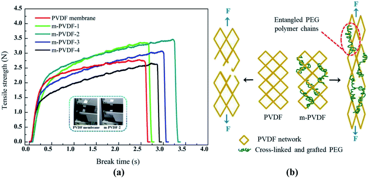 | ||
| Fig. 9 Mechanical strength of the prepared membranes. (a) Tensile strength versus time curve. (b) Schematic of the fracture mechanism of PVDF membrane and PVDF-g-PEG membranes. | ||
4. Conclusions
A novel interpenetrating network PVDF membrane containing linear PEG chain entanglement was successfully designed and prepared. The PVDF grafted with PEG chains has a structure and function similar to that of plant roots. Water molecules can pass through quickly while oil is rejected, and it also strengthens the separation layer. Experimental results show that the addition of PEG can effectively promote the orientation and growth of PVDF crystals. Thus, a membrane with enhanced hydrophilicity, increased porosity, and better mechanical strength is formed. Therefore, the grafted PEG has a dual function as surface hydrophilic modifier and pore former. These characteristics provide the preparative PVDF membrane with higher hydrophilicity, which improves the filtration performance and antifouling ability of the membrane. The WCA of m-PVDF-4 membrane is reduced from 87.87° to 54.49° compared with that of the blank PVDF membrane. The PVDF-g-PEG membranes can availably separate the oil/water emulsion, with high flux and oil rejection rates (>99.3%). Importantly, they also have excellent resistance to high-viscosity engine oils. The modified membrane has broad application prospect in the treatment of daily life and industrial oily wastewater. In addition, the developed modification strategy is simple and feasible. It can provide a simple and novel idea for the customization of other separation membranes, such as nanofiltration, reverse osmosis, and forward osmosis.Conflicts of interest
The authors declare that they have no known competing financial interests or personal relationships that could have appeared to influence the work reported in this paper.Acknowledgements
This work was supported by the following: National Science Fund for Distinguished Young Scholars (Grant No. 21925801), National Key Research and Development Program of China (Grant No. 2016YFC0402505), Guangdong Basic and Applied Basic Research Foundation (Grant No. 2021A1515010540) and Project funded by China Postdoctoral Science Foundation (Grant No. 2020M682884).References
- R. Li, J. Li, L. Rao, H. Lin, L. Shen, Y. Xu, J. Chen and B.-Q. Liao, J. Membr. Sci., 2021, 619, 118790 CrossRef CAS.
- J. Liu, S. Cheng, N. Cao, C. Geng, C. He, Q. Shi, C. Xu, J. Ni, R. M. DuChanois, M. Elimelech and H. Zhao, Nat. Nanotechnol., 2019, 14, 64–71 CrossRef CAS PubMed.
- H. Nawaz, M. Umar, A. Ullah, H. Razzaq, K. M. Zia and X. Liu, J. Hazard. Mater., 2020, 403, 123587 CrossRef PubMed.
- M. Elimelech and W. A. Phillip, Science, 2011, 333, 712–717 CrossRef CAS PubMed.
- T. E. Culp, B. Khara, K. P. Brickey, M. Geitner, T. J. Zimudzi, J. D. Wilbur, S. D. Jons, A. Roy, M. Paul, B. Ganapathysubramanian, A. L. Zydney, M. Kumar and E. D. Gomez, Science, 2021, 371, 72–75 CrossRef CAS PubMed.
- C. Liu, W. Wang, B. Yang, K. Xiao and H. Zhao, Water Res., 2021, 195, 116976 CrossRef CAS PubMed.
- C. Liu, Y. Guo, X. Wei, C. Wang, M. Qu, D. W. Schubert and C. Zhang, Chem. Eng. J., 2020, 384, 123306 CrossRef CAS.
- Y. Zhao, T. Sun, W. Liao, Y. Wang, J. Yu, M. Zhang, Z. Yu, B. Yang, D. Gui, C. Zhu and J. Xu, ACS Appl. Mater. Interfaces, 2019, 11, 22794–22800 CrossRef CAS PubMed.
- H. J. Tanudjaja, C. A. Hejase, V. V. Tarabara, A. G. Fane and J. W. Chew, Water Res., 2019, 156, 347–365 CrossRef CAS PubMed.
- X. Huang, W. Wang, Y. Liu, H. Wang, Z. Zhang, W. Fan and L. Li, Chem. Eng. J., 2015, 273, 421–429 CrossRef CAS.
- V. S. D. Voet, G. ten Brinke and K. Loos, J. Polym. Sci., Part A: Polym. Chem., 2014, 52, 2861–2877 CrossRef CAS.
- Q.-W. Su, H. Lu, J.-Y. Zhang and L.-Z. Zhang, J. Membr. Sci., 2019, 582, 367–380 CrossRef CAS.
- F. Beygmohammdi, H. Nourizadeh Kazerouni, Y. Jafarzadeh, H. Hazrati and R. Yegani, Chem. Eng. Res. Des., 2020, 154, 232–240 CrossRef CAS.
- Q. Bi, Q. Li, Y. Tian, Y. Lin and X. Wang, J. Appl. Polym. Sci., 2013, 127, 394–401 CrossRef CAS.
- M. Herzberg, A. Sweity, M. Brami, Y. Kaufman, V. Freger, G. Oron, S. Belfer and R. Kasher, Biomacromolecules, 2011, 12, 1169–1177 CrossRef CAS PubMed.
- Y. Gu, B. Zhang, Z. Fu, J. Li, M. Yu, L. Li and J. Li, J. Membr. Sci., 2021, 619, 118792 CrossRef CAS.
- M. Javadi, Y. Jafarzadeh, R. Yegani and S. Kazemi, Chem. Eng. Res. Des., 2018, 140, 241–250 CrossRef CAS.
- J. Lv, G. Zhang, H. Zhang and F. Yang, Chem. Eng. J., 2018, 352, 765–773 CrossRef CAS.
- C. Liu, J. Zhang, W. Wang, Y. Guo and K. Xiao, J. Membr. Sci., 2020, 611, 118354 CrossRef CAS.
- Q. Li, R. Yu, C. Zhu and Z. Jiao, Polym. Degrad. Stab., 2015, 114, 81–88 CrossRef CAS.
- A. Buttafava, G. Consolati, M. Mariani, F. Quasso and U. Ravasio, Polym. Degrad. Stab., 2005, 89, 133–139 CrossRef CAS.
- C. Liu, Y. Liu, Y. Guo, C. Wang, Z. Hu and C. Zhang, Chem. Eng. J., 2019, 357, 269–279 CrossRef CAS.
- D. He, H. Susanto and M. Ulbricht, Prog. Polym. Sci., 2009, 34, 62–98 CrossRef CAS.
- L. Zhang, G. Chen, H. Tang, Q. Cheng and S. Wang, J. Appl. Polym. Sci., 2009, 112, 550–556 CrossRef CAS.
- T. T. V. Tran, S. R. Kumar and S. J. Lue, J. Membr. Sci., 2019, 575, 38–49 CrossRef CAS.
- G. Zhang, Y. Li, A. Gao, Q. Zhang, J. Cui, S. Zhao, X. Zhan and Y. Yan, Chem. Eng. J., 2019, 369, 576–587 CrossRef CAS.
- H. Liu, X. Liu, F. Zhao, Y. Liu, L. Liu, L. Wang, C. Geng and P. Huang, J. Colloid Interface Sci., 2020, 562, 182–192 CrossRef CAS PubMed.
- Q. Wu, A. Tiraferri, T. Li, W. Xie, H. Chang, Y. Bai and B. Liu, ACS Omega, 2020, 5, 23450–23459 CrossRef CAS PubMed.
- L. Cui, M. Yao, B. Ren and K. S. Zhang, Anal. Chem., 2011, 83, 1709–1716 CrossRef CAS PubMed.
- C. Xu, W. Huang, X. Lu, D. Yan, S. Chen and H. Huang, Radiat. Phys. Chem., 2012, 81, 1763–1769 CrossRef CAS.
- C. Liu, J. Lee, J. Ma and M. Elimelech, Environ. Sci. Technol., 2017, 51, 2161–2169 CrossRef CAS PubMed.
- D. L. Zhao, W. S. Yeung, Q. Zhao and T.-S. Chung, J. Membr. Sci., 2020, 604, 118039 CrossRef CAS.
- Z. Yang, P. F. Sun, X. Li, B. Gan, L. Wang, X. Song, H. D. Park and C. Y. Tang, Environ. Sci. Technol., 2020, 54, 15563–15583 CrossRef CAS PubMed.
- Q. Ding, H. Yamamura, N. Murata, N. Aoki, H. Yonekawa, A. Hafuka and Y. Watanabe, Water Res., 2016, 101, 127–136 CrossRef CAS PubMed.
- C. Liu, Y. Guo, J. Zhang, B. Tian, O. Lin, Y. Liu and C. Zhang, RSC Adv., 2019, 9, 17766–17777 RSC.
- R. Dai, H. Guo, C. Y. Tang, M. Chen, J. Li and Z. Wang, Environ. Sci. Technol., 2019, 53, 13776–13783 CrossRef CAS PubMed.
- H. Sun, Y. Zhang, H. Sadam, J. Ma, Y. Bai, X. Shen, J.-K. Kim and L. Shao, J. Membr. Sci., 2019, 582, 1–8 CrossRef CAS.
- R. Ma, X. Lu, X. Kong, S. Zheng, S. Zhang and S. Liu, J. Membr. Sci., 2021, 620, 118936 CrossRef CAS.
- S. Liu, J.-W. Liu, H. Wang, Y.-X. Yang, S.-T. Liu, D. Hanigan and H.-Z. Zhao, Ind. Eng. Chem. Res., 2020, 59, 12114–12122 CrossRef CAS.
- J. Zhao, J. Y. Chong, L. Shi and R. Wang, J. Membr. Sci., 2020, 118914, DOI:10.1016/j.memsci.2020.118914.
- S. Gao, J. Sun, P. Liu, F. Zhang, W. Zhang, S. Yuan, J. Li and J. Jin, Adv. Mater., 2016, 28, 5307–5314 CrossRef CAS PubMed.
- S.-H. Park, S. J. Kwon, M. G. Shin, M. S. Park, J. S. Lee, C. H. Park, H. Park and J.-H. Lee, Desalination, 2018, 436, 28–38 CrossRef CAS.
| This journal is © The Royal Society of Chemistry 2021 |

