 Open Access Article
Creative Commons Attribution 3.0 Unported Licence
Investigation of shear-induced rearrangement of carbon nanotube bundles using Taylor–Couette flow†
Haemin Leea,
Jinhwan Parka,
Hyunjung Chob,
Jaegeun Lee *c and
Kun-Hong Lee*a
aDepartment of Chemical Engineering, Pohang University of Science and Technology, 77 Cheongam-Ro, Nam-gu, Pohang, Gyeongbuk 37673, Republic of Korea. E-mail: ce20047@postech.ac.kr; Tel: +82-54-279-2003
bLG Chem R&D Campus Daejeon, 188 Munji-ro, Yuseong-gu, Daejeon, 34122, South Korea
cSchool of Chemical Engineering, Pusan National University, 2 Busandaehak-ro 63 Beon-gil, Geumjeong-gu, Busan, 46241, Republic of Korea. E-mail: jglee@pusan.ac.kr; Tel: +82-51-510-2495
First published on 26th November 2021
Abstract
Macroscopic assemblies of carbon nanotubes (CNTs) usually have a poor alignment and a low packing density due to their hierarchical structure. To realize the inherent properties of CNTs at the macroscopic scale, the CNT assemblies should have a highly aligned and densified structure. Shear-aligning processes are commonly employed for this purpose. This work investigates how shear flows affect the rearrangement of CNT bundles in macroscopic assemblies. We propose that buckling behavior of CNT bundles in a shear flow causes the poor alignment of CNT bundles and a low packing density of CNT assemblies; the flow pattern and the magnitude of shear stress induced by the flow are key factors to regulate this buckling behavior. To obtain CNT assemblies with a high packing density, the CNTs should undergo a laminar flow that has a sufficiently low shear stress. Understanding the effect of shear flow on the structure of CNT bundles may guide improvement of fabrication strategies.
1. Introduction
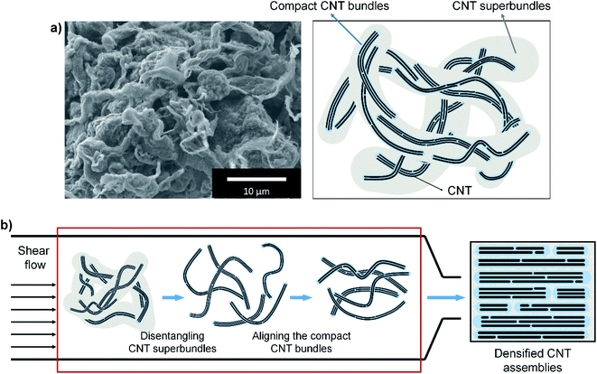
Carbon nanotubes (CNTs) can form macroscopic assemblies like CNT fibers or films, which typically have hierarchical structures (Fig. 1a).1–4 Individual CNTs form compact CNT bundles, in which adjacent CNTs strongly attract each other by strong van der Waals (vdW) forces due to their closeness;1,2,5–7 these compact bundles seem to have a highly densified structure.1 The compact bundles are loosely entangled by weak vdW force and form large CNT superbundles.8,9 These superbundles are physically entangled and attract each other weakly in CNT fibers and films.1,3,9,10 As a result, numerous voids of micrometer scale and smaller, inevitably form in CNT assemblies.1,3,9,10The properties of CNT fibers and films depend significantly on their packing density. The mechanical strength relies dominantly on the inter-tube frictions, and electrical conductivity is dependent on the contact area between CNTs and the number of contacts.1,4,11–15 Therefore, to fabricate strong and highly conductive CNT fibers and films, they should be perfectly densified at and below the micrometer scale. To achieve high packing density, an aligned structure of CNTs is most desirable.4,16 Theoretical studies predict that the properties of CNT fibers could be comparable to those of individual CNTs, if the CNT fiber is composed of sufficiently long CNTs (length/diameter > 105) and is perfectly densified.4,17
Shear-aligning methods are a promising approach to obtain fibers and films that have highly aligned and densified structure.18 Flow-induced shear stress arranges particles in the flow direction. The methods are applicable to various systems regardless of their chemistry,19–21 and are advantageous in mass production; for example, the method of extrusion has been widely used in industry.22
Most studies that reported on shear-aligning methods have tried to disperse CNTs individually before aligning by functionalizing CNTs or using surfactants.23–26 Damages induced by functionalization and residual surfactants might decrease the mechanical properties and the electrical conductivity of CNT assemblies.27,28 Using super-acid or polyelectrolyte solutions, it is possible to disperse CNTs without functionalization.6,7,27–30 However, these methods are only applicable to CNTs with high crystallinity, and are difficult to handle because they use troublesome reagents (e.g., super-acid or sodium).4,6,16,27,28,30 Several studies improved the alignment of CNTs by applying shear force directly to CNT assemblies without dispersing them,1,31 but small-scale voids were not effectively removed.
We expect that highly aligned and densified assemblies of CNTs can be obtained by aligning and densifying these compact CNT bundles without debundling the compact bundles (Fig. 1b), because the compact CNT bundles seem to have a highly aligned and densified structure. The loosely entangled CNT bundles can be easily disentangled into compact CNT bundles in shear flow without introducing damage or using additional materials.32 We tried to disentangle and align loosely entangled CNT bundles by using shear flow. In order to effectively control the structure of CNT assemblies, it is necessary to clearly understand the effect of shear flow on the disentangling and aligning of bundles.
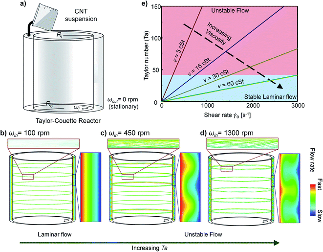
Here, we investigate how shear flows affect the rearrangement of CNT bundles by considering disentanglement and alignment of them. We used a Taylor–Couette (TC) reactor to develop various flows. The TC reactor consists of two concentric cylinders and can control the flow pattern and the magnitude of shear stress.19,33–36 We assessed the effect of shear flows by observing the morphology of CNT buckypapers that had been subjected to flows with different condition. Unstable flow always led to highly entangled structures, whereas laminar flow could generate either entangled or highly densified structures, depending on the shear stress induced by flows. When laminar flow has sufficiently high shear stress, the obtained CNT bundles were highly entangled, which was counterintuitive. We propose that buckling behavior of CNT bundles causes the poor alignment of CNT bundles and the low packing density of CNT assemblies, and that this behavior is dependent on both the flow pattern and the shear stress. Our results can help to increase understanding of the mechanisms of change in the microstructure of CNT materials and may guide development of methods to fabricate CNT materials that have desired structures.
2. Materials and methods
2.1. Materials
We used single-walled CNTs (Zeon Nano Technology Co., Ltd., Japan) that have diameter of 3–5 nm and length >100 μm. They were mixed with solvents (butyl benzoate or benzyl benzoate) purchased from Sigma-Aldrich. The solvents were chosen by considering the Hansen solubility parameter and the viscosity.2.2. Formation of CNT buckypapers under various flow conditions
A customized TC reactor was used to develop various flows selectively. This reactor consists of two concentric cylinders, separated by a gap of 2 mm (outer radius Rout: 42 mm, inner radius Rin: 40 mm). The cylinders are made of Teflon and can rotate individually; the rotation rate ωin of the inner cylinder was controlled up to 1500 rpm (corresponds to an apparent shear rate![[small gamma, Greek, dot above]](https://www.rsc.org/images/entities/char_e0a2.gif) = 3000 s−1), while the outer cylinder was fixed stationary (ωout = 0 rpm).
= 3000 s−1), while the outer cylinder was fixed stationary (ωout = 0 rpm).
The CNTs were mixed with the solvents and stirred at 300 rpm for >1 day. The mixture of CNTs and solvent was introduced into the gap between the cylinders, and the inner cylinder was rotated. After TC flow mixing, the CNT buckypapers were fabricated by vacuum filtration, then rinsed sequentially with ethanol and deionized water to remove residual solvent and dried in a vacuum oven at 100 °C.
2.3. Characterization
The CNT suspensions developed in the TC reactor were characterized using an optical microscope (OM) (BX53F, OLYMPUS), an ultraviolet-visible-near infrared (UV-vis-nIR) spectroscope (S-3100, Scinco), the zeta-potential (ELSZ-100-, Otsuka Electronics), and a viscometer (DHR-1, TA Instruments). In OM measurements, the thickness of the CNT suspensions was fixed at 0.2 mm. To observe the UV-vis-nIR absorbance, the CNT suspensions were loaded in a quartz cuvette with a 1 cm path length and sealed with a Teflon stopper. A scanning electron microscope (SEM, XL30S FEG, FEI), Raman spectroscopy (LabRam Aramis, Horiba Jobin Yvon), and Fourier-transform infrared (FT-IR) spectrometer (Nicolet iS50, Thermo Scientific) were used to characterize the CNT buckypapers.3. Results and discussion
3.1. The control of flow pattern and magnitude of shear stress using the Taylor–Couette reactor
Our strategy to study the effect of shear flow is to observe the variation in the average thickness and the alignment of CNT bundles subjected to various flow conditions. For this purpose, we used a TC reactor because it enables control of the flow pattern and the magnitude of the shear stress by changing the rotational speed of each cylinder, and the viscosity of fluids.19,33–36The pattern of TC flows could be inferred from the Taylor number Ta.37 If the outer cylinder is fixed stationary as in our system (Fig. 2a), then
 | (1) |
The flow-induced shear stress is τ = ![[small gamma, Greek, dot above]](https://www.rsc.org/images/entities/char_e0a2.gif) η, where η is the dynamic viscosity of the suspension.
η, where η is the dynamic viscosity of the suspension. ![[small gamma, Greek, dot above]](https://www.rsc.org/images/entities/char_e0a2.gif) is defined as38
is defined as38
 | (2) |
![[small gamma, Greek, dot above]](https://www.rsc.org/images/entities/char_e0a2.gif) increase as the particle approaches the surface of the inner cylinder (r → Rin). Particles experience different shear stress depending on their r; we chose τ0 = τ(r = Rin) as characteristic shear stress and
increase as the particle approaches the surface of the inner cylinder (r → Rin). Particles experience different shear stress depending on their r; we chose τ0 = τ(r = Rin) as characteristic shear stress and ![[small gamma, Greek, dot above]](https://www.rsc.org/images/entities/char_e0a2.gif) 0 =
0 = ![[small gamma, Greek, dot above]](https://www.rsc.org/images/entities/char_e0a2.gif) (r = Rin) as characteristic shear rate to represent the flow conditions of the system.
(r = Rin) as characteristic shear rate to represent the flow conditions of the system.
The relationship between Ta and ![[small gamma, Greek, dot above]](https://www.rsc.org/images/entities/char_e0a2.gif) 0 was calculated from eqn (1) and (2) by substituting appropriate ν and ωin (Fig. 2e). As the ν of the suspension increased, the flow can remain stable at a substantially high
0 was calculated from eqn (1) and (2) by substituting appropriate ν and ωin (Fig. 2e). As the ν of the suspension increased, the flow can remain stable at a substantially high ![[small gamma, Greek, dot above]](https://www.rsc.org/images/entities/char_e0a2.gif) 0.
0.
We measured the ν of CNT suspensions at various conditions and calculated the Ta and τ0 of flows at each condition (Table 1 and Fig. S1†). Thus, at either laminar or unstable flow regime, flows that induce a wide range of shear stress can be obtained in the TC reactor simply by changing solvents, CNT concentration, and ωin (Table 1).
| Conc. [mg mL−1] | ωin [rpm] | Solvent | |||
|---|---|---|---|---|---|
| Butyl benzoate | Benzyl benzoate | ||||
| Ta | τ0 [Pa] | Ta | τ0 [Pa] | ||
| 1 | 100 | 11.5 | 3.64 | 4.58 | 9.21 |
| 450 | 179 | 4.76 | 42.2 | 20.3 | |
| 1300 | 518 | 13.7 | 148 | 48 | |
| 3 | 100 | 4.47 | 9.43 | 2.46 | 17.2 |
| 450 | 46.3 | 18.4 | 21.1 | 40.5 | |
| 1300 | 180 | 39.5 | 96.3 | 74.1 | |
| 5 | 100 | 2.24 | 18.8 | 1.08 | 39 |
| 450 | 22.7 | 37.7 | 15.9 | 53.7 | |
| 1300 | 89.9 | 79.4 | 68.8 | 104 | |
| 10 | 100 | 0.95 | 44.6 | 0.24 | 177 |
| 450 | 11.0 | 77.5 | 4.68 | 182 | |
| 1300 | 47.7 | 151 | 38.5 | 185 | |
3.2. Disentangling the CNT bundles in the shear flow
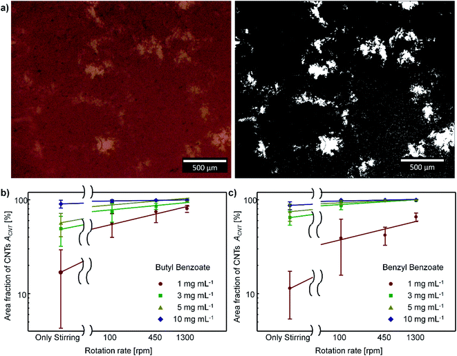
To improve the efficiency of shear-aligning, loosely entangled superbundles in the CNT aggregates should first be fully disentangled in the flow. Shear flow can disentangle entangled CNT structures when the shear stress induced by flow is larger than the attractive force between CNTs.39,40 We observed OM images and the UV-vis-nIR absorbance of the CNT suspensions to assess the disentanglement of CNT bundles at each flow condition.The level of disentanglement of CNT bundles can be qualitatively observed using SEM, TEM, and OM.41–47 These microscopy images intuitively show the size distribution of CNT bundles.45–47 However, CNT bundles in the suspensions would form an entangled mesh network structure at high CNT concentration.44 Accordingly, the OM images of CNT suspensions show that CNT bundles form mesh network structures (Fig. 3a left), which complicates the comparison of the disentanglement level of CNT bundles. Thus, a quantitative approach must be employed to assess the degree of disentanglement of CNT bundles.
At a fixed volume fraction of CNTs in the suspension, the total area covered by CNTs in the suspension should increase as the size of CNT bundles decreases. Hence, the size of CNT bundles can be inferred from the area covered by CNTs in the suspension. We can assess the variation of the area covered by CNTs from the area fraction of CNTs ACNT in the OM images, and the ACNT is defined as the fraction of the area covered by CNTs to the total area. The ACNT is obtained from different CNT suspensions by using Image J software (Fig. 3a).
ACNT was much higher in the CNT suspension that had been subjected to TC flow than in the suspension prepared by a mere stirring at 300 rpm (Fig. 3b and c). ACNT increased as ωin increased. This result is consistent with the results of previous studies that reported decrease in the size of particle aggregates with increasing shear rate when flow-induced shear stress is sufficiently strong.38,48 We conclude that the shear stress induced by the rotating TC flow is sufficiently strong to disentangle the CNT bundles.
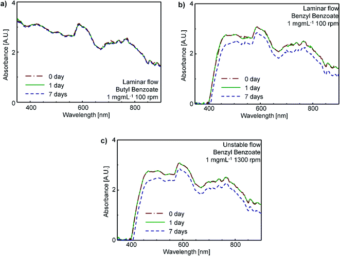
To test the stability of CNT suspensions, the UV-vis-nIR absorption spectra of the CNT suspensions were obtained on days 0, 1 and 7 after treatment. These spectra changed little regardless of the flow characteristics (Fig. 4); this result indicates a high stability of the disentangled bundles in the suspensions.
The UV-vis-nIR absorption spectra also provide information about the level of disentanglement of CNTs in the suspension. If SWCNTs are individually dispersed in the suspensions, the UV-vis-nIR absorbance of CNT suspensions should show multiple sharp peaks due to van Hove's singularity, whereas when the CNTs exist as bundles in the suspension, the absorption peaks should be broad.49 The CNT suspensions after the TC mixing showed broad absorption peaks at the vis-nIR region (Fig. 4), which indicates that most CNTs in the suspension retained the bundled structures after the TC mixing. Hence, we conclude that the shear stresses induced by the TC flow are not strong enough to completely disintegrate the CNT bundles and disperse CNT individually.
To summarize, the flow-induced shear stress is strong enough to disintegrate large, loosely-entangled superbundles of CNTs to compact CNT bundles, but not strong enough to disintegrate the compact CNT bundles to individual CNTs. This limitation indicates that the interaction force within a compact CNT bundle exceeds the magnitude of effective shear stress defined as the difference between shear stress acting on CNTs within a bundle. The effective shear stress that acts on a CNT bundle should depend on its size (Fig. S2†). The large superbundles are loosely entangled so they will experience stronger effective shear stress and be more apt to disintegrate easily than the small compact bundles (ESI†).
Although the compact CNT bundles do not disintegrate in the shear flow, they assume a highly aligned and densified structure.1 Extrusion of these compact CNT bundles may enable production of a CNT assembly that has a highly aligned and densified structure (Fig. 1b).
3.3. Aligning the CNT bundles in the shear flow
We tried to identify how shear flow affects the alignment of CNT bundles. Direct measurement is impractical,40 so we observed the morphology of buckypapers produced by vacuum filtration of various CNT suspensions (Fig. 5). Pristine CNTs and buckypapers that had been subjected to stirring at 300 rpm had rough surfaces that bore huge aggregated superbundles (Fig. 5a and b), whereas buckypapers that had been subjected to TC flows had a flat and dense structure with few big aggregated bundles (Fig. 5c). These results show that TC flow can effectively disentangle huge CNT aggregates; this conclusion is consistent with OM images.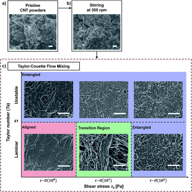 | ||
| Fig. 5 SEM images of pristine CNT powders and CNT buckypapers at processing steps: (a) pristine CNT powder, (b) after stirring at 300 rpm, and (c) after TC mixing. Scale bars: 10 μm. | ||
We confirmed that TC flow did not cause a significant change in the intrinsic properties of CNTs. The Raman spectroscopy and the FT-IR spectroscopy show that the shear stress induced by the TC flow does not cause a meaningful change in the defect concentration and functional group on the CNT surface (Fig. S3†). The zeta-potential ζ of CNT suspensions had a negligibly small value (ζ ∼ 0 mV), which indicates that the shear aligning process does not change the surface charge of CNTs.
To understand in detail how the characteristics of TC flow affect the alignment of CNT bundles in buckypapers that were obtained after TC flow mixing, we categorized the SEM images of the papers according to their Ta and τ0.
Interestingly, at Ta < 41 (laminar flow), the CNT buckypapers can have either the entangled structure or the highly-densified structure, depending on the τ0 (Fig. 5c). The CNT assembly was dense and aligned structure when τ0 ∼ 100 Pa, but highly entangled at τ0 ∼ 102 Pa. This result is counterintuitive, so we tried to understand why it happened.
We suggest that it is a result of shear flow causing buckling behavior of CNT bundles. Rod-like particles rotate even in laminar flow, and during the rotation, they can buckle.50–54 This buckling causes poor alignment of rod particles, and yields a macroscopic assembly that has an undensified structure.20 This buckling behavior is controlled by the interplay of the elastic bending force and shear stresses.50,55–58
If the shear stress induced by flow is below the threshold stress τcrit for buckling, the rod particles rotate in the flow without any deformation in their shape,50,55 but at shear stress > τcrit, the shear flow drives the structural instability during the rotation.50,59 According to Euler buckling theory:50,57,59–61
| τcrit ∼ (EI)/(a2b2) | (3) |
The structure of CNT bundles in a buckypaper varied with their thickness (Fig. 5c). This result supports our argument that the buckling behavior of CNT bundles induces the poor alignment of CNT bundles. At τ0 ∼ 101 Pa (transition region in Fig. 5c), aligned and buckled bundles coexist. CNT bundles that have small diameter formed the buckled structure, whereas the thick CNT bundles became aligned. This result indicates that τcrit of a CNT bundle increases with increase in its thickness.
At Ta > 41 (unstable secondary flow), CNT buckypapers had flat, meshed structures, and the CNT bundles seem to become increasingly wavy as τ0 increased (Fig. 5). These entangled structures seem to occur due to the vortexes in the flow. Multi-axial shear forces act on the CNT bundles as the direction of local flow constantly changes due to the presence of numerous vortexes in unstable flows.39,40,44 The CNT bundles should rotate and buckle in accordance with the flow directions.
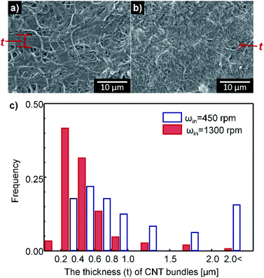
The disaggregation and morphologies of rod-like particles are affected by the scale of the smallest vortexes.63–65 When the particles are larger than the scale of smallest vortexes, the disaggregation and the buckling behaviors are dominant.65 The scale of the smallest vortexes can be defined as Kolmogorov's length scale Lk, which decreases as the Reynolds number increases (Lk ∼ Re−3/4 ∼ (ωin/ν)−3/4).64,65 Thus, the average thickness of CNT bundles should decrease as ωin increases. In agreement with this prediction, CNT bundles subjected to ωin = 450 rpm were thicker (avg. t = 1.3 μm) than those that had undergone ωin = 1300 rpm (avg. t = 0.51 μm) (Fig. 6).
To summarize, we propose that the wavy structure of CNT bundles is caused by the buckling behavior of CNT bundles in shear flow, so to obtain highly densified CNT assemblies, these behaviors should be prevented. For this purpose, the CNTs should be subjected to laminar flow with a sufficiently low shear stress.
4. Conclusion
We investigated how shear flows affect the rearrangement of CNT bundles by using a TC reactor. We found that the shear stress induced by TC flow could disintegrate loosely-entangled superbundles of CNTs into small, compact CNT bundles, but was not strong enough to disintegrate compact CNT bundles into individual CNTs. We also studied how shear flow aligns CNT bundles. In unstable secondary flow, the CNT bundles bend and become randomly entangled due to vortexes in flow. In laminar flow, interestingly, the alignment of CNT bundles is dependent on the magnitude of the shear stress induced by flow. We propose that the buckling behavior of CNT bundles in a shear flow causes the poor alignment of CNT bundles and a low packing density of CNT assemblies; the flow pattern and the magnitude of shear stress induced by the flow are key factors that regulate this buckling behavior. The understanding on the effect of shear flow can help guide development of methods to fabricate macroscopic CNT assemblies such as CNT fibers, films, and buckypapers with desired microscopic structures.Author contributions
Haemin Lee: conceptualization, data curation, formal analysis, investigation, methodology, visualization, writing – original draft, Jinhwan Park: software, visualization, Hyunjung Cho: investigation, methodology, visualization, Jaegeun Lee: conceptualization, formal analysis, methodology, visualization, supervision, writing – review & editing, Kun-Hong Lee: funding acquisition, resource, supervision, writing – review & editing.Conflicts of interest
There are no conflicts of interest to declare.Acknowledgements
This work was funded by Grant No. 2E31330 from the Korea Institute of Science and Technology (KIST) Open Research Program. This work was also supported by the National Research Foundation of Korea (NRF) grant funded by the Korea government (MSIT) (No. 2020R1G1A1013953).References
- H. Cho, H. Lee, E. Oh, S.-H. Lee, J. Park, H. J. Park, S.-B. Yoon, C.-H. Lee, G.-H. Kwak, W. J. Lee, J. Kim, J. E. Kim and K.-H. Lee, Carbon, 2018, 136, 409–416 CrossRef CAS.
- J. Park, J. Lee, D.-M. Lee, S.-H. Lee, H. S. Jeong, K.-H. Lee and S. M. Kim, Carbon, 2019, 152, 151–158 CrossRef CAS.
- J. J. Vilatela, R. Khare and A. H. Windle, Carbon, 2012, 50, 1227–1234 CrossRef CAS.
- J. Lee, D.-M. Lee, Y. Jung, J. Park, H. S. Lee, Y.-K. Kim, C. R. Park, H. S. Jeong and S. M. Kim, Nat. Commun., 2019, 10, 1–10 CrossRef PubMed.
- L. A. Girifalco, M. Hodak and R. S. Lee, Phys. Rev. B: Condens. Matter Mater. Phys., 2000, 62, 13104–13110 CrossRef CAS.
- A. N. G. Parra-Vasquez, N. Behabtu, M. J. Green, C. L. Pint, C. C. Young, J. Schmidt, E. Kesselman, A. Goyal, P. M. Ajayan, Y. Cohen, Y. Talmon, R. H. Hauge and M. Pasquali, ACS Nano, 2010, 4, 3969–3978 CrossRef CAS PubMed.
- S. Ramesh, L. M. Ericson, V. A. Davis, R. K. Saini, C. Kittrell, M. Pasquali, W. E. Billups, W. W. Adams, R. H. Hauge and R. E. Smalley, J. Phys. Chem. B, 2004, 108, 8794–8798 CrossRef CAS.
- T. Gennett, A. Dillon, J. Alleman, K. Jones, F. Hasoon and M. Heben, Chem. Mater., 2000, 12, 599–601 CrossRef CAS.
- Y. Zhao, J. Choi, P. Kim, W. Fei and C. J. Lee, RSC Adv., 2015, 5, 30564–30569 RSC.
- C. Jiang, X. Yang, J. Zhao, Q. Li, K.-Q. Zhang, X. Zhang and Q. Li, Appl. Surf. Sci., 2018, 436, 66–72 CrossRef CAS.
- R. J. Headrick, D. E. Tsentalovich, J. Berdegué, E. A. Bengio, L. Liberman, O. Kleinerman, M. S. Lucas, Y. Talmon and M. Pasquali, Adv. Mater., 2018, 30, 1704482 CrossRef PubMed.
- J. J. Vilatela, J. A. Elliott and A. H. Windle, ACS Nano, 2011, 5, 1921–1927 CrossRef CAS PubMed.
- N. Behabtu, M. J. Green and M. Pasquali, Nano Today, 2008, 3, 24–34 CrossRef CAS.
- J. Qiu, J. Terrones, J. J. Vilatela, M. E. Vickers, J. A. Elliott and A. H. Windle, ACS Nano, 2013, 7, 8412–8422 CrossRef CAS PubMed.
- Y. Jung, T. Kim and C. R. Park, Carbon, 2015, 88, 60–69 CrossRef CAS.
- J. Lee, D.-M. Lee, Y.-K. Kim, H. S. Jeong and S. M. Kim, Small, 2017, 13, 1701131 CrossRef PubMed.
- J. Hearle, Text. Res. J., 1965, 35, 1060–1071 CrossRef.
- W. Eom, E. Lee, S. H. Lee, T. H. Sung, A. J. Clancy, W. J. Lee and T. H. Han, Nat. Commun., 2021, 12, 1–8 CrossRef PubMed.
- D. Vennerberg and M. R. Kessler, Carbon, 2014, 80, 433–439 CrossRef CAS.
- J. J. Martin, M. S. Riederer, M. D. Krebs and R. M. Erb, Soft Matter, 2015, 11, 400–405 RSC.
- K. Yasuda, T. Kyuto and N. Mori, Rheol. Acta, 2004, 43, 137–145 CrossRef CAS.
- D. Guell and A. Bénard, in Flow-induced alignment in composite materials, Elsevier, 1997, pp. 1–42 Search PubMed.
- R. Haggenmueller, S. S. Rahatekar, J. A. Fagan, J. Chun, M. L. Becker, R. R. Naik, T. Krauss, L. Carlson, J. F. Kadla and P. C. Trulove, Langmuir, 2008, 24, 5070–5078 CrossRef CAS PubMed.
- V. C. Moore, M. S. Strano, E. H. Haroz, R. H. Hauge, R. E. Smalley, J. Schmidt and Y. Talmon, Nano Lett., 2003, 3, 1379–1382 CrossRef CAS.
- F. Wei, Z. Feng, W. Xiao-Gong, W. Mei-Xiang, F. Akihiko and Y. Katsumi, Chin. Phys. Lett., 2003, 20, 753 CrossRef.
- J. N. Barisci, M. Tahhan, G. G. Wallace, S. Badaire, T. Vaugien, M. Maugey and P. Poulin, Adv. Funct. Mater., 2004, 14, 133–138 CrossRef CAS.
- C. Jiang, A. Saha, C. C. Young, D. P. Hashim, C. E. Ramirez, P. M. Ajayan, M. Pasquali and A. A. Marti, ACS Nano, 2014, 8, 9107–9112 CrossRef CAS PubMed.
- D. D. Tune, A. J. Blanch, C. J. Shearer, K. E. Moore, M. Pfohl, J. G. Shapter and B. S. Flavel, ACS Appl. Mater. Interfaces, 2015, 7, 25857–25864 CrossRef CAS PubMed.
- V. A. Davis, A. N. G. Parra-Vasquez, M. J. Green, P. K. Rai, N. Behabtu, V. Prieto, R. D. Booker, J. Schmidt, E. Kesselman, W. Zhou, H. Fan, W. W. Adams, R. H. Hauge, J. E. Fischer, Y. Cohen, Y. Talmon, R. E. Smalley and M. Pasquali, Nat. Nanotechnol., 2009, 4, 830–834 CrossRef CAS PubMed.
- S.-H. Lee, J. Park, J. H. Park, D.-M. Lee, A. Lee, S. Y. Moon, S. Y. Lee, H. S. Jeong and S. M. Kim, Carbon, 2021, 173, 901–909 CrossRef CAS.
- D. Tune, B. Stolz, M. Pfohl and B. Flavel, Nanoscale, 2016, 8, 3232–3236 RSC.
- K. Chiou, S. Byun, J. Kim and J. Huang, Proc. Natl. Acad. Sci. U. S. A., 2018, 115, 5703–5708 CrossRef CAS PubMed.
- C. D. Andereck, S. Liu and H. L. Swinney, J. Fluid Mech., 1986, 164, 155–183 CrossRef.
- S. Grossmann, D. Lohse and C. Sun, Phys. Fluids, 2014, 26, 025114 CrossRef.
- K.-H. Nam, U. J. Kim, M. H. Jeon, T.-R. Lee, J. Yu, N.-H. You, Y.-K. Kim, J. W. Suk and B.-C. Ku, Chem. Eng. J., 2020, 391, 123482 CrossRef CAS.
- A.-M. Nabila, S. Poncet and G. Abdelrahmane, Am. J. Fluid Dyn., 2015, 5, 17–22 Search PubMed.
- M. Fardin, C. Perge and N. Taberlet, Soft Matter, 2014, 10, 3523–3535 RSC.
- T. Serra, J. Colomer and X. Casamitjana, J. Colloid Interface Sci., 1997, 187, 466–473 CrossRef CAS PubMed.
- S.-E. Lee and S.-H. Park, Composites, Part A, 2017, 95, 118–124 CrossRef.
- H. Yoon, M. Yamashita, S. Ata, D. N. Futaba, T. Yamada and K. Hata, Sci. Rep., 2014, 4, 1–8 CrossRef.
- S. P. K. Medisetti and N. Roberts, Role of Dispersion and Functionalization on Mechanical Properties in Carbon Nanotube-Polymer Composite, Utah State University, 2017 Search PubMed.
- B. Lively, P. Smith, W. Wood, R. Maguire and W.-H. Zhong, Composites, Part A, 2012, 43, 847–855 CrossRef CAS.
- T. Glaskova, M. Zarrelli, A. Aniskevich, M. Giordano, L. Trinkler and B. Berzina, Compos. Sci. Technol., 2012, 72, 477–481 CrossRef CAS.
- K. Kobashi, S. Ata, T. Yamada, D. N. Futaba, M. Yumura and K. Hata, Chem. Sci., 2013, 4, 727–733 RSC.
- S. Pegel, P. Pötschke, G. Petzold, I. Alig, S. M. Dudkin and D. Lellinger, Polymer, 2008, 49, 974–984 CrossRef CAS.
- T. Villmow, P. Pötschke, S. Pegel, L. Häussler and B. Kretzschmar, Polymer, 2008, 49, 3500–3509 CrossRef CAS.
- H. Khare and D. Burris, Polymer, 2010, 51, 719–729 CrossRef CAS.
- G. Frappier, B. Lartiges and S. Skali-Lami, Langmuir, 2010, 26, 10475–10488 CrossRef CAS PubMed.
- M. J. O'connell, S. M. Bachilo, C. B. Huffman, V. C. Moore, M. S. Strano, E. H. Haroz, K. L. Rialon, P. J. Boul, W. H. Noon and C. Kittrell, Science, 2002, 297, 593–596 CrossRef PubMed.
- A. Durin, P. De Micheli, J. Ville, F. Inceoglu, R. Valette and B. Vergnes, Composites, Part A, 2013, 48, 47–56 CrossRef CAS.
- G. B. Jeffery, Proc. R. Soc. London, Ser. A, 1922, 102, 161–179 Search PubMed.
- S. A. Abtahi and G. J. Elfring, Phys. Fluids, 2019, 31, 103106 CrossRef.
- R. Libanori, F. H. Münch, D. M. Montenegro and A. R. Studart, Compos. Sci. Technol., 2012, 72, 435–445 CrossRef CAS.
- M. P. Murrell and M. L. Gardel, Proc. Natl. Acad. Sci. U. S. A., 2012, 109, 20820–20825 CrossRef CAS PubMed.
- Y. Liu, B. Chakrabarti, D. Saintillan, A. Lindner and O. Du Roure, Proc. Natl. Acad. Sci. U. S. A., 2018, 115, 9438–9443 CrossRef CAS PubMed.
- S. B. Lindström and T. Uesaka, Phys. Fluids, 2007, 19, 113307 CrossRef.
- F. Gittes, B. Mickey, J. Nettleton and J. Howard, Int. J. Biochem., 1993, 120, 923–934 CAS.
- K. Okeyoshi, R. Kawamura, R. Yoshida and Y. Osada, Sci. Rep., 2015, 5, 1–6 Search PubMed.
- V. A. Kuzkin and M. M. Dannert, Acta Mech., 2016, 227, 1645–1652 CrossRef.
- J. Kang, M. Huang, M. Zhang, N. Zhang, G. Song, Y. Liu, X. Shi and C. Liu, J. Reinf. Plast. Compos., 2020, 39, 473–484 CrossRef CAS.
- X. E. Li, W. Lehman and S. Fischer, J. Struct. Biol., 2010, 170, 313–318 CrossRef CAS PubMed.
- B. I. Yakobson and L. S. Couchman, J. Nanopart. Res., 2006, 8, 105–110 CrossRef CAS.
- A. Gurvich and A. Yaglom, Phys. Fluids, 1967, 10, S59–S65 CrossRef.
- M. Takeuchi, M. J. Doubell, G. A. Jackson, M. Yukawa, Y. Sagara and H. Yamazaki, Sci. Rep., 2019, 9, 1–8 CAS.
- M. Sulaiman, E. Climent, B. Delmotte, P. Fede, F. Plouraboué and G. Verhille, Eur. Phys. J. E: Soft Matter Biol. Phys., 2019, 42, 1–11 CrossRef PubMed.
Footnote |
| † Electronic supplementary information (ESI) available: The simulation of the Taylor–Couette flow, rheological behaviors of CNT suspensions, and detailed analysis of shear stress induced by the flow. See DOI: 10.1039/d1ra07354k |
| This journal is © The Royal Society of Chemistry 2021 |

