CVD carbon-coated carbonized loofah sponge loaded with a directionally arrayed MXene aerogel for electromagnetic interference shielding†
Songtao
Li
 ab,
Jiashun
Wang
 ab,
Zhengwang
Zhu
ab,
Dongyan
Liu
ab,
Wanchong
Li
ab,
Zhengwang
Zhu
ab,
Dongyan
Liu
ab,
Wanchong
Li
 *a,
Guoxin
Sui
 *ab and
Chul B.
Park
 *c
*c
aShi-changxu Innovation Center for Advanced Materials, Institute of Metal Research, Chinese Academy of Sciences, No. 72 Wenhua Road, Shenhe District, Shenyang 110016, China. E-mail: gxsui@imr.ac.cn; liwanchong@imr.ac.cn
bSchool of Materials Science and Engineering, University of Science and Technology of China, No. 72 Wenhua Road, Shenhe District, Shenyang 110016, China
cMicrocellular Plastics Manufacturing Laboratory, Department of Mechanical and Industrial Engineering, University of Toronto, Toronto, Ontario M5S 3G8, Canada. E-mail: park@mie.utoronto.ca; Tel: +1 416 978 3053
First published on 26th November 2020
Abstract
Sustainably regenerated, environmentally friendly, natural loofah sponge is promising to become a multi-functional bio-carbon material, especially in the field of electromagnetic shielding, due to its unique hierarchical structure. In this work, highly efficient electromagnetic shielding composites were obtained based on CVD carbon-coated carbonized loofah sponge (CCLS) and directionally arrayed MXene aerogels through a simple and pollution-free freeze-drying method. The three-dimensional skeleton of CCLS was able to provide a mechanically strong support for the MXene aerogel and endow the composites with a good foundation network for electric conduction and shielding electromagnetic waves. When the CVD carbon coating time was 60 hours, the compressive strength and modulus of CCLS reached 0.979 MPa and 10.881 MPa, respectively, and an electrical conductivity of 28.34 S m−1 was attained. In particular, the directionally arrayed MXene aerogel with a microporous structure filled the macropore vacancies in the CCLS skeleton, giving the composite prominent anisotropy. The maximum conductivity and average total electromagnetic shielding effectiveness of the composites prepared achieved levels of 55.99 S m−1 and 70.0 dB, respectively. Importantly, the composite showed excellent flame resistance and thermal stability. The electromagnetic shielding effectiveness value of the composites could still reach 42.6 dB after being burnt in an alcohol flame for 120 s. This research could further widen the practical application and development of natural biological materials and aerogels in various fields such as aerospace, medical equipment, electronic devices, and energy management.
Introduction
With the advancement of electrical and electronic devices, the requirement for highly efficient electromagnetic interference (EMI) shielding materials has become increasingly urgent.1 The materials and preparation techniques used for shielding have been remarkably developed and improved. Multi-functional carbonaceous materials, such as carbon fibers,2 carbon black,3 carbon nanotubes,4 and graphene,5 are ideal candidates for shielding material due to their light weight, high strength, good electrical conductivity, and strong corrosion resistance. However, conventional carbon materials have consumed non-renewable sources to some extent or caused an adverse impact on ecosystems, which accelerates the depletion of fossil resources together with the pollution of the natural environment. Hence, sustainable, renewable, environmentally benign, and inexpensive biomaterials to replace or partially replace fossil resources and chemical materials are gaining more and more popularity. Naturally derived wood,6 peanut shells,7 walnut shells,8 egg shells,9 corn starch,10 waxberry,11 bamboo,12 and loofah13 have been investigated for utilization as the raw material. Among them, natural loofah has been exploited as a shielding material with remarkable electromagnetic shielding performance, which is ascribed to its unique three-dimensional (3D) porous biological structure. Owing to being a kind of electromagnetic wave transparent material (Fig. S1 of the ESI†) originating from its nature of insulation (1.79 × 10⁻¹² S m−1), loofah needs to be carbonized to get good conductivity. In previous work,14,15 the basic characteristics of loofah were researched in depth, and the multiple properties of loofah fibers and sponges were explored to serve as EMI shielding materials. Using a simple and effective treatment method, the problem that natural loofah sponges were too brittle to be self-supporting after carbonization was solved. However, further research revealed that there were still some tiny defects on the surface of carbonized loofah sponges, which needs to be modified if the sponges are to be used as supporting structural materials. Therefore, it is essential to improve the mechanical properties of carbonized loofah sponge to achieve reliable application in a real engineering environment.With regard to the EMI shielding mechanism, the shielding effectiveness (SE) is strongly related to the structural characteristics of the shielding material. Besides the traditional direct blending of the filler and matrix, researchers have developed other advanced methods to construct continuous 3D conducting networks, such as foaming,16 template-based methods,17in situ polymerization,18 separation structure manufacturing,19 and the sol–gel process (aerogels).20 Aerogels have drawn widespread attention from scientists due to their prominent merits, including light weight, porous structure, easy preparation, high material utilization rate, non-pollution, etc. More importantly, the inter-connected 3D network of aerogels endows them with high conductivity and excellent EMI shielding performance. Many researchers choose graphene oxide, natural cellulosic materials, and new two-dimensional (2D) MXenes as candidates for the preparation of conductive aerogels with superior versatility in the field of electromagnetic shielding. For example, Jiang et al.21 fabricated a graphene aerogel with a layered structure by mechanical compression, freeze-drying and thermal annealing, achieving an electrical conductivity of 181.8 S m−1 and SE of 43.29 dB. Greiner et al.22 prepared an anisotropic composite aerogel consisting of cellulose nanofibrils and silver nanowires using directional freeze-drying, which had a high EMI SE of up to ∼81.2 dB at 12.4 GHz and sensitive pressure sensing (errors <0.26%). Cai et al.23 reported that an ultralight MXene aerogel obtained by a freeze casting route reached a SE of 75 dB. Xie et al.24 developed an MXene/graphene hybrid foam via freeze-drying and reduction heat treatment exhibiting a SE of 50.7 dB. By using a bidirectional freezing method, Koo et al.25 prepared a porous MXene/carbon nanotube hybrid aerogel, which had a superior electrical conductivity of 943.0 S m−1 and SE of 103.9 dB. However, during the aerogel preparation process, fillers usually overlap each other by hydrogen bonding interactions between the hydroxyl-containing groups, forming a hollow structure with ultra-high porosity. Consequently, most aerogels lack mechanical strength, especially aerogels obtained by freeze-drying of aqueous solutions of a single component. These aerogels are so weak that they are difficult to process further. Therefore, it is still a bottle neck for aerogel materials to be better applied to practical engineering products with easy processability.
In this work, an effective combination of carbonized loofah sponge and an MXene aerogel gave full play to the complementary advantages of the two materials and made up for their shortcomings. A few layers of dense carbon were first coated on the carbonized loofah sponge by chemical vapor deposition (CVD) to repair the microscopic surface defects on the bio-carbon, providing a perfect supporting substrate to fasten the weak MXene aerogel. Then, a directionally arrayed microporous MXene aerogel was constructed to fill the macroscopic pores of the CVD carbon-coated carbonized loofah sponge skeletons. As expected, the composites prepared demonstrated excellent EMI shielding performance, electrical conductivity, rational mechanical strength, flame resistance and thermal stability. In addition, the mechanism of anisotropy given to the composite by the directional alignment of the MXene aerogel was analyzed in detail. This study may open up an avenue for the better development and use of aerogels and loofah sponges.
Experimental section
Materials
MAX (Ti3AlC2) phase powder was supplied by the Institute of Metal Research, Chinese Academy of Sciences. Lithium fluoride (LiF, ≥99% purity), hydrochloride acid (HCl, 37% purity) and ethyl alcohol (EtOH, 99.8% purity) were purchased from the National Medicine Group Chemical Reagent Co., Ltd. Natural Loofah was obtained from Xundangchu Furnishing Co., Ltd, Liaocheng, China. Phenolic resin (PR) was purchased from Shanghai Macklin biochemical Co., Ltd.Preparation of CVD carbon-coated carbonized loofah sponge
The loofah sponge was prepared by making some modifications to a previously published method.15 In this process, the uniform loofah segments were first selected, and then cut and cleaned. Next, the irregular loofah segments were flattened and dried on a heated press in order to obtain neat loofah sponge cuboids. Then, the entire loofah sponge was cut into small pieces with a size of 15 mm × 30 mm × (∼12 mm), and the outermost and innermost layers of all the loofah sponge pieces were removed, leaving the middle layer with a uniform texture (Scheme 1a). The pretreated loofah sponge pieces were immersed in a PR solution at ambient temperature for 8 hours. The components of the PR solution were 60 wt% PR and 40 wt% EtOH. The PR-coated loofah sponges were then cured at 150 °C for 2 hours in an oven. Next, the cured PR-coated loofah sponges were put into in a tube furnace at 800 °C for 2 hours to obtain the carbonized PR-coated loofah sponge (CPLS) (Scheme 1b). Finally, the surface of the CPLS was coated with a carbon layer by CVD treatment to further strengthen its skeleton. The detailed process parameters were as follows: the temperature was 1000 °C, the gas source was propane and the carbon coating time was 16, 40, and 60 hours. The samples obtained were designated as CCLS-16, CCLS-40, and CCLS-60.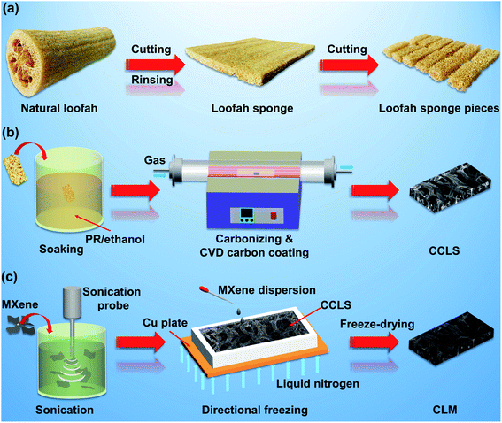 | ||
| Scheme 1 (a) Schematic illustration of the preparation process of the loofah sponge, (b) CVD carbon-coated carbonized loofah sponge, (c) and CCLS-60/MXene aerogel composite. | ||
Preparation of CCLS-60/MXene aerogel composites
The MXene fabrication technique has been developed to a mature state, and the detailed preparation instructions can be found in related literature.26 In this study, the in situ hydrofluoric acid (HF) etching method was adopted to fabricate the MXene. The specific process is described as follows: 1.2 g of LiF was added to a 9 M HCl solution prepared by diluting 15 mL of HCl (37% purity) with 5 mL of deionized water, and the mixture was magnetically stirred for 10 min until the LiF was completely dissolved. Next, 1.0 g of MAX phase powder was carefully added to the solution little by little to avoid overheating, after which the mixture was kept at 40 °C for 28 hours under magnetic stirring at a speed of 550 rpm. Then, the mixture was diluted and centrifuged with deionized water several times until the PH of the supernatant liquid got close to 6. Finally, the diluted mixture was filtered with vacuum assistance using a polytetrafluoroethylene (PTFE) film (pore size: 0.45 μm), and the resulting sample was collected by freeze-drying.A certain amount of MXene powder was dispersed in deionized water by using an ultrasonic cell disruptor for 10 min to fabricate 10, 15, and 20 mg mL−1 of MXene dispersions. Then, CCLS-60 was immersed in the MXene dispersion, and the mixture was directionally frozen with liquid nitrogen (Scheme 1c). The composite obtained was designated as CLM. In order to explore the anisotropy of composites, directional freezing was performed in the lateral and longitudinal directions of the CCLS-60/MXene dispersion mixture. The composites obtained were designated as CLM= and CLM‖. Meanwhile, the CCLS-60/MXene dispersion mixture was also frozen in a refrigerator to prepare a randomly arrayed MXene composite as a comparative sample, designated as CLM . The specific sample parameters and preparation process are shown in Table 1 and Fig. S2.†
| Properties | ρ a (g cm−3) | ρ b (g cm−3) | ρ c (g cm−3) | ρ d (g cm−3) | P (%) | T (mm) | C (mg mL−1) |
|---|---|---|---|---|---|---|---|
a
ρ
a: the density of pure loofah sponges; ρb: the density of PR-coated loofah sponges; ρc: the density of carbonized PR-coated loofah sponges; ρd: the density of the CCLS or CLM; P: the porosity of the sample; T: the thickness of the sample; C: the concentration of MXene dispersion; ‖: longitudinal direction; =: lateral direction;  : disordered direction. : disordered direction.
|
|||||||
| CPLS | 0.1014 ± 0.0095 | 0.1828 ± 0.0087 | 0.1630 ± 0.0083 | 0.1630 ± 0.0083 | 92.23 ± 0.40 | 3.23 ± 0.03 | |
| CCLS-16 | 0.1014 ± 0.0095 | 0.1828 ± 0.0087 | 0.1630 ± 0.0083 | 0.1705 ± 0.0153 | 91.88 ± 0.73 | 3.23 ± 0.03 | |
| CCLS-40 | 0.1014 ± 0.0095 | 0.1828 ± 0.0087 | 0.1630 ± 0.0083 | 0.1907 ± 0.0101 | 91.88 ± 0.48 | 3.23 ± 0.03 | |
| CCLS-60 | 0.1014 ± 0.0095 | 0.1828 ± 0.0087 | 0.1630 ± 0.0083 | 0.2014 ± 0.0142 | 90.41 ± 0.68 | 3.23 ± 0.03 | |
| CLM10= | 0.2159 ± 0.0040 | 3.23 ± 0.03 | 10 | ||||
| CLM15= | 0.2349 ± 0.0048 | 3.23 ± 0.03 | 15 | ||||
CLM20=/‖/ |
0.2483 ± 0.0106 | 3.23 ± 0.03 | 20 | ||||
Characterization
Scanning electron microscopy (SEM, JSM-6301F, JEOL) was used to observe the surface morphology of CPLS, CCLS, and CLM. The microstructure of the MXene was imaged with a FEI Talos-F200X transmission electron microscope (TEM). X-ray diffraction (XRD) spectra of samples were recorded with a D/Max2500 PC instrument, which used Cu-Kα radiation with a wavelength of 0.154 nm, and the test range was from 5° to 80°. The elemental compositions of the MAX phase and MXene were measured by X-ray photoelectron spectroscopy (XPS, Thermal VG/ESCALAB250) with Al-Kα radiation. The compression properties of CPLS, CCLS, and CLM were measured on a WSM-20 kN universal test machine in accordance with ASTM D695-15. The specimen size was 12.5 × 12.5 × 8.5 (mm). The compression test speed was 0.1 mm min−1, and the average of three measurements was used as the result. The electrical conductivity of the samples was analyzed with a KEITHLEY 2000 and 6517B equipment. The EMI shielding parameters of CPLS, CCLS, and CLM were determined with an Agilent N5230A series vector network analyzer. The test parameters are detailed in the ESI.† The thermal stability of all samples was examined by thermogravimetric analysis (TGA, Netzsch, STA449F5) under air atmosphere. The samples were tested at a heating (cooling) rate of 10 °C min−1 within the temperature range of 35–850 °C.Results and discussion
Surface morphology, microstructure, and phase analysis of CPLS, CCLS, CLM, MAX, and MXene
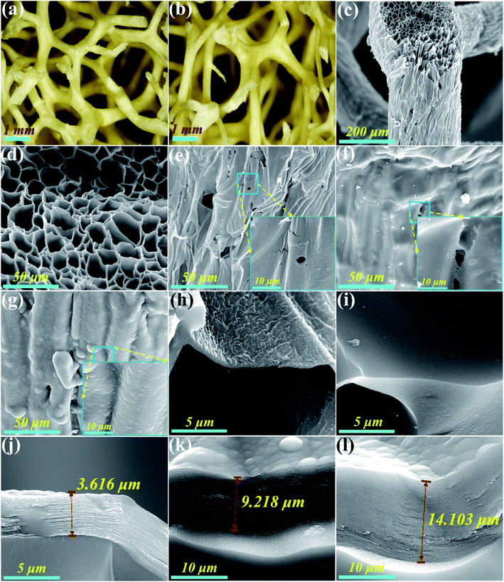
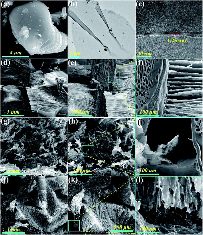
Fig. 1a and b show the top and side views of a natural loofah sponge piece, which reveals that the intertwined loofah fibers naturally grow together and constitute an interconnective 3D porous network structure. Moreover, the entire structure of loofah fiber is well retained after carbonization treatment (Fig. 1c). It can be seen from Fig. 1d that the cross section of carbonized loofah fiber is composed of many polygonal pores, resembling a honeycomb structure. On account of the high temperature pyrolysis, some wrinkles appear on the outer surface of the carbonized loofah fiber, and there are many cracks and micropores on its surface, which may reduce the mechanical properties of the entire carbonized loofah sponge (Fig. 1e). After the loofah fiber is coated with a layer of PR followed by carbonization, it can be clearly observed that the outer surface of the carbonized PR-coated loofah fiber is smoother than that without PR coating, and the cracks and part of the micropores have been repaired. However, there are still defective micropores on the outer surface of the carbonized loofah fiber, which may result from some tiny bubbles remaining during the curing process (Fig. 1f). In order to further repair the surface defects of the carbonized loofah fiber, the CVD technique is used to strengthen the PR-coated loofah fibers after carbonization. Fig. 1g shows that the outer surface of the carbonized loofah fiber is successfully coated with a solid carbon layer so that all cracks and micropores are repaired. Moreover, the longer the carbon coating time, the thicker the carbon coating layer on the outer surface of the carbonized loofah fibers (3.616–14.1043 μm), and the densification of surface carbon could be conducive to the enhancement of the mechanical performance of the carbonized loofah sponge skeleton (Fig. 1h–l). Although the loofah sponge is subjected to PR coating and CVD carbon coating treatment, most of the internal polygonal pores of the carbonized loofah fibers are not blocked (Fig. S3 of the ESI†), which is still an advantage for the carbonized loofah sponge to shield the electromagnetic wave.Fig. 2a shows the surface morphology of the MAX phase. It can be clearly seen that the side of the MAX phase is stepped and has a smooth surface. After etching, the parent MAX phase is converted to a lamellar 2D MXene with only a few layers, and the interlayer spacing is approximately 1.25 nm (Fig. 2b and c). The few-layer MXene possesses superior electrical and thermal properties and can be well dispersed in water in order to integrate with other functional materials to achieve various composites with outstanding multifunctionality.27 The MXene aerogels shown in Fig. 2d–f and j–l are directionally arranged in the skeleton of CCLS, indicating that the two materials are well combined. Furthermore, the arrangement direction of MXene sheets is different for the two composites, i.e., parallel and vertical to the incident direction of the electromagnetic wave, respectively (Fig. S2 of the ESI†). The arrangement direction of the MXene sheets of CLM= and CLM‖ cross sections is vertical to each other, indicating that the CLM composites obtained have an anisotropy structure. The difference in the arrangement direction of the MXene aerogel is able to be controlled by directional freezing. By contrast, as depicted in Fig. 2g–i, the MXene aerogels without being directionally frozen form a disordered arrangement in the composite.
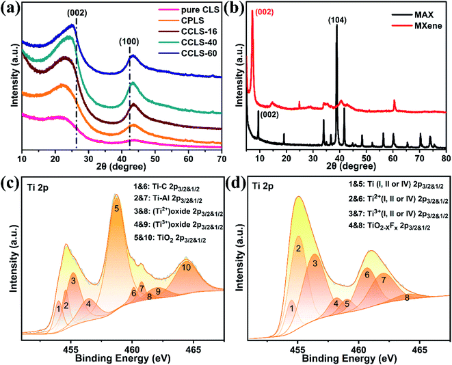
Fig. 3a shows that the pure carbonized loofah sponge (pure CLS) has two broad peaks at 21.04° and 43.90°, corresponding to the reflection of graphite (002) and (100), respectively. The pure CLS is classified as amorphous carbon according to the authors' previous work15 and reports from other researchers.28 The two broad peaks begin to protrude slightly and shift toward the standard crystalline peak of graphite after the natural loofah sponge is PR coated and carbonized, locating at 21.62° and 43.56°, respectively. With the increase of carbon coating time, the two broad peaks of CCLS gradually become more convergent and convex, and the degree of peak shift increases. When the carbon coating time was 60 hours, the two peaks of CCLS shift to 24.88° and 43.44°, suggesting that the crystallization degree of surface carbon on CCLS is higher than that on the original CPLS,29,30 which is beneficial for the electrical and mechanical properties of the carbonized loofah sponge skeleton.
In addition, the structure and chemical composition of the MAX phase and MXene were analyzed in detail. Fig. 3b depicts the comparative XRD patterns of the raw MAX phase and MXene etched by the in situ HF solution. The (002) peak of the MAX (Ti3AlC2) phase located at 9.50° shifts to the lower 2θ degree (about 7.15°) corresponding to the (002) peak of the MXene (Ti3C2Tx), indicating that the Al element was exfoliated by the in situ HF solution.31 The changes of the 2θ degree may also be partially attributed to the intercalation of lithium ions. Meanwhile, the peak at 38.94° reflecting the MAX phase is barely present in the XRD spectrum of the MXene, and a series of (00l) peaks representing the high order of the C direction of the MXene appear, which further confirms the successful exfoliation of the MAX phase. Moreover, the Raman spectra of the MAX phase and MXene also illustrate the above results (Fig. S4 of the ESI†). The surface chemical elements of the MAX phase and MXene were evaluated by XPS. The coexistence of Ti–Al, Ti–C, (Ti2+) Oxide and (Ti3+) Oxide in the MAX phase is evidenced by the shoulders on the main peaks at 454.63 eV (Fig. 3c). The Ti 2p3/2 peak at 458.70 eV and its shakeup satellite peak at 464.39 eV correspond to TiO2, which originates from the oxidation of the MAX (Ti3AlC2) phase with the oxygen in the air during the XPS analysis.32 The Ti 2p region for the MXene shows features assigned to Ti (I, II or IV), Ti2+ (I, II or IV), Ti3+ (I, II or IV), and TiO2−xFx, which confirms the presence of surface functional groups (–O, –OH, and –F) (Fig. 3d). The loss of the Ti–Al bond in the MXene Ti 2p spectrum also further proves the successful exfoliation of the MAX phase.33
Mechanical performance of CPLS, CCLS, and CLM
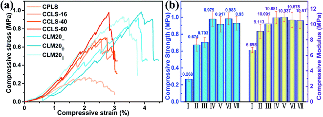
The natural loofah sponge cannot form a stable skeleton after direct carbonization, so it could hardly be applied in an engineering environment. In this work, a process of coating the natural loofah sponge with PR before carbonization was adopted, as introduced in detail in previous work,15 which could stabilize the sponge skeleton and improve its mechanical performance. Nevertheless, the resulting carbonized loofah sponge skeleton still has some surface defects, which are fully disclosed by the morphology analysis. Therefore, the CVD technique is used to further enhance the mechanical properties of the carbonized loofah sponge skeleton. Fig. 4a shows the typical compressive stress–strain curves of the CPLS, the CCLS, and the CLM. It can be found from the curves that, with the increase of the CVD carbon coating time, the compressive strength of CCLS becomes higher, which amply proves that the CVD technique plays a vital role for the carbonized loofah sponge to act as a strong supporting skeleton. Meanwhile, the enhancement of the mechanical properties of CCLS enables it to be used as a high-performance multifunctional material by combining with MXene aerogels. As mentioned in the introduction, the combination of CCLS and MXene aerogels not only remedies the weakness in the aerogels' mechanical performance, but also assists in filling the macroporous vacancies in the CCLS skeletons. In addition, it can be seen from the changes in the stress–strain curves that there are zigzag fluctuations in the compressive strength. Because some of the intertwined loofah fibers, which construct the porous skeleton of the pristine loofah sponge, are left dangling during the cutting process, the individual dangling fibers are isolated without interconnecting with other fibers. Therefore, when the compressive stress reaches a certain value, the fracture of the independent fibers might result in the fluctuations in the curves. Fortunately, the small-scale fluctuations originate merely from the fracture of individual fibers without causing the collapse of the whole carbonized loofah sponge skeleton. Fig. 4b shows the comparative results of the compressive strength and modulus of the CPLS, the CCLS, and the CLM. The maximum compressive strength of CPLS is up to 0.268 MPa, which is high enough for an independent support skeleton. When the carbonized loofah sponge skeleton is carbon coated by CVD for 16 hours, the compressive strength of CCLS-16 increases to 0.674 MPa, which is 2.5 times that of CPLS. Along with the increase of the time of CVD carbon coating, the compressive strength of CCLS continues to increase, and the maximum compressive strength of CCLS-60 reaches 0.979 MPa. The compressive modulus of all the carbonized loofah sponge skeletons also rises with the increase of CVD carbon coating time. Particularly, the compression modulus of CCLS-16 increases by approximately 40% compared with that of CPLS. Additionally, the results show that there is little difference in the compressive performance of the CLM20=, CLM20 , and CLM20‖ composites. The measured data of these composites are similar to that of CCLS-60, suggesting that the contribution of CCLS-60 is far higher than that of the aerogel to the compression resistance of CLM composites. The good compressive performance of the CLM also indicates the strong support effect of CCLS-60 for the aerogel. Table 2 summarizes the mechanical properties of other similar shielding composites with different network structures. Obviously, the pure aerogels are extremely weak, so it is essential to have the support material like electrically insulating polymers to strengthen themselves. Unfortunately, it is well known that electrically insulating polymers hardly attenuate the incident electromagnetic wave. Although the polymer matrices have a mechanical support effect for entire electromagnetic shielding composites, they do not contribute to the electrical conductivity of the composites. Apparently, in addition to their conductivity, the CLM composites in the present work have advantageous mechanical properties over the most reported materials, suggesting that CCLS-60 is more beneficial as a support material for aerogels in many aspects.
| Materials | Structure | Mechanical strength (MPa) | Thickness (mm) | SE (dB) | Specific SE (dB mm−1) | Ref. |
|---|---|---|---|---|---|---|
| a T: tensile strength; C: compressive strength; F: flexural strength; Es: storage modulus; PVDF: poly (vinylidene fluoride); EMA: ethylene methyl acrylate; EOC: ethylene octane copolymer; CB: carbon black; PI: polyimide; PPy: polypyrrole; rGO: reduced graphene oxide; EP: epoxy PS: polystyrene. | ||||||
| CB/EMA/EOC | Hybrid networks | 8.0/T | 2.0 | 31.4 | 15.7 | 3 |
| Graphene/PI | Porous structure | 0.05/C | 2.5 | 22.0 | 8.8 | 5 |
| PPy/wood | Porous structure | 15.46/C | 3.5 | 58.0 | 16.6 | 6 |
| rGO/MXene/EP | Honeycomb | 7565.6/Es | 3.0 | 55.0 | 18.3 | 17 |
| MXene/PS | Segregated networks | 2266.0/Es | 2.0 | 54.0 | 27.0 | 19 |
| rGO | Layered porous structure | 2.5 | 43.3 | 17.3 | 21 | |
| Silver/cellulose | Sponge | 5.2 × 10⁻³/C | 3.0 | 81.2 | 27.1 | 22 |
| rGO/MXene | Sponge | 0.4 × 10⁻³/C | 1.5 | 35.0 | 23.3 | 24 |
| CNT/MXene | Sponge | 2.25 × 10⁻³/C | 3.0 | 103.9 | 34.6 | 25 |
| rGO/epoxy | Anisotropic networks | 1210.0/Es | 4.0 | 32.0 | 8.0 | 35 |
| CLM20= | Composite porous structure | 0.917/C | 3.23 | 70.0 | 21.7 | This work |
Electrical conductivity of CPLS, CCLS, and CLM
Fig. 5 illustrates the electrical conductivity of CPLS, CCLS, and CLM. Obviously, the electrical conductivity of CPLS improves greatly after CVD carbon coating treatment. The conductivity of CCLS-16 reaches 19.73 S m−1, which is 6.9 times that of CPLS (2.84 S m−1). The improvement of carbonized loofah sponge skeleton conductivity is because the CVD carbon coating repairs the surface defects on the carbonized loofah fibers and densifies the amorphous carbon of carbonized loofah sponge skeletons, which is conducive to the conduction of free electrons. Furthermore, it is well verified by the XRD patterns that the amorphous carbon structure of carbonized loofah fibers tends to the standard crystalline carbon structure of graphite with the increase of CVD carbon coating time. The better the carbon crystallinity, the faster will be the conduction velocity of the transferred electrons. There is another possible reason for increased conductivity which is that, when the CVD carbon is coated on the surface of carbonized loofah fibers, the carbon-coated layer becomes thicker as the carbon coating time increases, which might shorten the distance of the conduction path between carbonized loofah fibers, leading to the enhancement of the electrical conductivity. When the CVD carbon coating time is 60 hours, the conductivity of CCLS-60 reaches 28.34 S m−1. In addition, the CLM composites also show good conductivity due to increasing the conduction path of free electrons when the macroporous vacancies of the carbonized loofah sponge skeletons are filled with the microporous MXene aerogels, the 2D sheet MXene of which itself possesses excellent conductivity.34 With the increase of MXene dispersion concentration, the electrical conductivity of CLM composites increases gradually (CLM10=: 34.37 S m−1, CLM15=: 36.39 S m−1, and CLM20=: 43.93 S m−1). It is worth noting that the electrical conductivity of some aerogels with different MXene sheet orientations and different MXene dispersion concentrations is not discussed in this article. According to the characteristics of the directional arrangement of the aerogel and research reports in other literature,35 aerogels in which MXene sheets and incident electromagnetic waves are arranged perpendicular to each other are more conducive to attenuating electromagnetic waves. Hence, this study focuses on researching the laterally arranged MXene aerogels for the purpose of simplifying the experimental scheme. In order to make the experiment more systematic, using the MXene dispersion with a concentration of 20 mg mL−1 as a representative, the variation of the conductivity of CLM in different MXene arrangement directions of the aerogel was explored. The conductivity of the pure MXene aerogel was reported to be 87.0 and 10.0 S m−1 for longitudinal and lateral directions, respectively.25 The experimental results reveal that CLM20‖ attains maximum electrical conductivity (55.99 S m−1). It can be seen from the SEM images of CLM composites that the longitudinal arranged of MXene aerogels could be more beneficial to the free electron conduction than the other two arrangements. There is a certain gap between the MXene sheet layers of the laterally arranged aerogel, resulting in a barrier effect on the conduction of free electrons.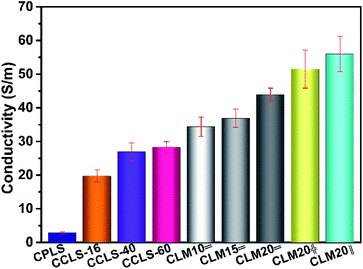 | ||
| Fig. 5 The conductivity of the carbonized loofah sponge skeletons and their composites combined with MXene aerogels. | ||
EMI shielding performance of CPLS, CCLS, and CLM
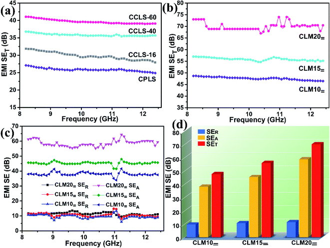
Fig. 6a shows the change in the total shielding effectiveness (SET) of the PR-coated loofah sponges undergoing carbonization followed by CVD carbon coating for different times. It can be seen from the test results that all curves remain stable over the X-band, and thus the average EMI SE value was used for analysis and discussion for convenience and ease of explanation. Although the average SET of CPLS is merely 25.9 dB, this value exceeds the standards requirements (20.0 dB) for commercial application. Additionally, with the thickening of the CVD carbon-coated layer on the surface of carbonized loofah fiber, the average SET of CCLS gradually increases from 29.8 dB for CCLS-16 to 39.7 dB for CCLS-60. On the one hand, the CVD carbon coating treatment causes the original amorphous carbon of carbonized loofah fiber with microporous defects to be much denser, thereby improving the conductivity of CCLS, which further leads to the increase of ohmic dissipation caused by interaction between the incident electromagnetic waves and CCLS. On the other hand, as the thickness of the CVD carbon-coated layer increases, more conductive layers will interact with incident electromagnetic waves, consequently improving the EMI shielding performance of CCLS. The shielding effectiveness value of shielding materials is related to the material thickness. In general, as the thickness of the shielding materials increases, the shielding effectiveness rises, which can be verified from the derivation formula of the EMI shielding effectiveness and lots of related research reports.36,37 Furthermore, the carbonized loofah sponge retains the internal microporous structure of the fibers after undergoing CVD carbon coating treatment, which also helps to attenuate electromagnetic waves due to the increase in interface interactions. In this work, a unique process method is designed in which the carbonized loofah sponge skeletons are used as the supporting material to combine with MXene aerogels (the SET of the pure MXene aerogel with a thickness of 3.0 mm is able to reach 65.56 dB25). This achieves the complementary combination of microporous aerogels filling the macropores of the carbonized loofah sponge skeletons so as to fabricate highly efficient EMI shielding composites. Fig. 6b shows the EMI SE values of CLM composites prepared by combining CCLS-60 with directional frozen aerogels containing MXene concentrations of 10, 15, and 20 mg mL−1. With these three concentrations of MXene dispersion, the MXene sheets prepared by directional freezing are all consistently perpendicular to the incident electromagnetic waves, which can be proven by the SEM images of the CLM= cross section (Fig. 2d–f). The average SET of CLM10= is 47.6 dB. When the concentration of the MXene dispersion increases to 20 mg mL−1, the average SET of CLM20= reaches 70.0 dB, indicating that 99.9999999% of the electromagnetic waves are intercepted. The filling of MXene aerogels enhances the interaction with incident electromagnetic waves and attenuates some electromagnetic waves that could possibly escape from the macropores of carbonized loofah sponge skeletons. Moreover, as the concentration of MXene dispersion increases, there will be more conductive layers to interact with the incident electromagnetic waves, which gives rise to the increase of ohmic loss.1In general, when incident electromagnetic waves interact with EMI shielding materials, the reflection and adsorption of electromagnetic waves will occur, so the SET is mainly composed of shielding absorption effectiveness (SEA) and shielding reflection effectiveness (SER).2 It is well known that the conventional EMI shielding materials are dominated by metals, which are endowed with a large number of conduction electrons and superior conductivity, resulting in a mass of electromagnetic wave reflections due to the interface impedance mismatch between a medium (air) and the metal surface.6 Accordingly, metals are EMI shielding materials dominated by shielding reflection. However, if a shielding material dominated by shielding reflection is used in precision instruments, it may cause secondary electromagnetic pollution due to a large number of reflected electromagnetic waves, resulting in the malfunction of instruments. In consequence, when exploiting a new EMI shielding material, researchers usually expect to create a shielding material dominated by absorption. Hence, the shielding mechanism of the CLM composites is analyzed in detail by comparison of SEA and SER.
Fig. 6c and d show the variation of SEA and SER of CLM over 8.2–12.4 GHz and the comparison of the mean values of three shielding efficiencies in the whole frequency band. When the concentration of MXene dispersion increases, the SER values of CLM do not change a lot (CLM10=: 9.5 dB; CLM15=: 10.6 dB; CLM20=: 11.3 dB). In contrast, the SEA values of CLM vary greatly, rising from 38.1 dB for CLM10= to 58.7 dB for CLM20=. Furthermore, the increasing trend of the CLM SEA is consistent with that of the CLM SET, which amply attests to the fact that the prepared CLMs are EMI shielding composites dominated by absorption, suggesting that CLM is suitable for the requirements of modern industrial development. The power coefficients corresponding to the SER, SEA, and SET of CLM composites are also detailedly analyzed and discussed in the ESI (Fig. S5†) to explain the EMI shielding mechanism.
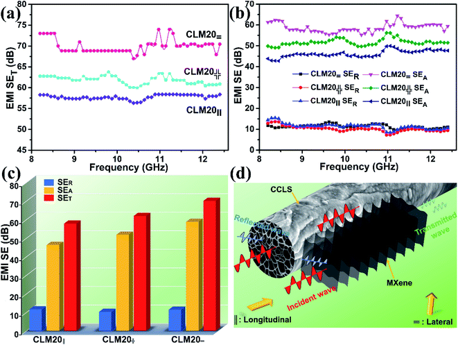
In addition, when the concentration of MXene dispersion is 20 mg mL−1, the electromagnetic shielding performance of CLM composites with MXene aerogels with three different alignment directions is also analyzed in detail. The internal structure of these three CLM composites is such that the arrangement directions of the three MXene sheets form different angles with the direction of incident microwaves—perpendicular to each other (CLM20=), parallel to each other (CLM20‖) and disorderly crossing each other (CLM20 ). It is seen from Fig. 7a that the average SET value of CLM20= is the highest, while that of CLM20‖ is the lowest. When the electromagnetic waves are all vertically projected on the MXene sheets, CLM20= can intercept more electromagnetic waves relative to CLM20‖, which can also be verified by the differential changes of SER and SEA in these three CLM composites (Fig. 7b and c). The results show that the SER values of the three CLM composites have almost no difference, while the SEA value of CLM20= is much higher than that of CLM20‖, indicating that there is more interaction between CLM20= and the electromagnetic waves to produce stronger ohmic dissipation, which in turn improves the shielding properties of CLM20=. Fig. 7d shows a schematic diagram of the interaction mechanism between CLM20= and incident electromagnetic waves. The laterally arranged MXene sheets form a structure similar to rows of baffles, where the electromagnetic waves between the baffle layers will be continuously attenuated due to the production of interfacial polarization, assisting CCLS to effectively intercept vertically incident electromagnetic waves. In contrast, the longitudinally aligned MXene sheets are parallel to the incident electromagnetic waves (Fig. S6 of the ESI†), so there are fewer interface interactions between the electromagnetic waves and MXene sheets of CLM20‖ compared with CLM20=, leading to an unsatisfactory shielding effect. The highly efficient composite porous structure is further highlighted by comparing the EMI shielding performances of CLM20= with those reported in the literature (Table 2). It is seen from lists that the CLM composites hold certain potential application value and competitive advantage.
Thermal stability and flame resistance of CPLS, CCLS, and CLM
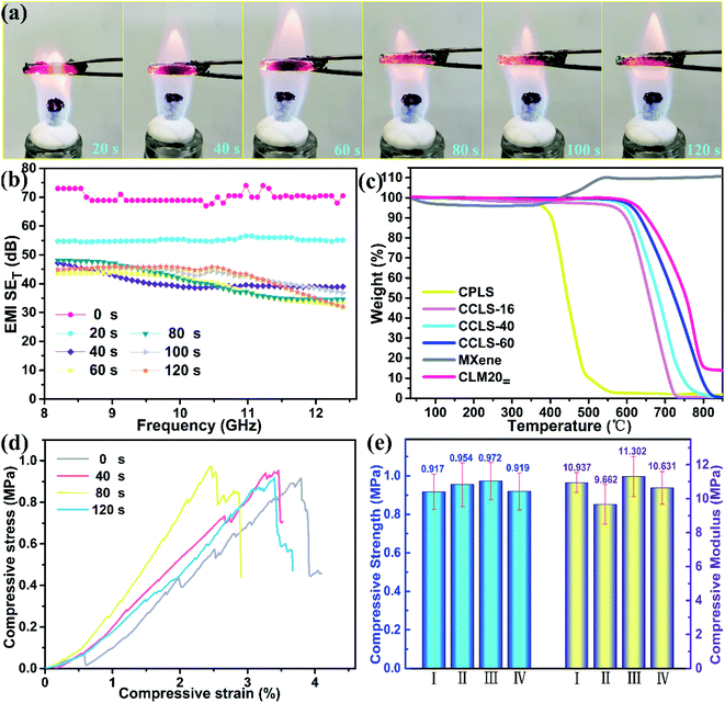
Thermal stability and flame resistance are also important parameters for a material to be used in a real environment. Functional materials may fail due to the impact of the thermal environment, and may even affect the failure of other surrounding components. It can be seen from Fig. 8a that the burning reaction of CLM20= is more severe in the first 20 s due to the oxidation of the MXene. As the burning time increases, the MXene aerogel is gradually oxidized until it becomes completely TiO2 (Fig. S7 of the ESI†).38 Although the MXene is transformed into TiO2, it still could be effective in attenuating incident electromagnetic waves because TiO2 is a good microwave absorbent.39,40 Additionally, the composite does not show obvious burning for 120 s; in particular, the CCLS-60 skeleton in the composite always remained stable, indicating that the composite has good flame resistance. In order to further explore the effect of burning on the composite, the electromagnetic shielding performance of CLM20= is analyzed after burning for 0 to 120 s, as shown in Fig. 8b. The results show that the average SET value of CLM20= decreases from 70.0 dB to 55.2 dB when the burning time was from 0 to 20 s. As the burning time continued to increase, the electromagnetic shielding performance of CLM20= tends to be stable, and its average SET value decreases to 40.6, 39.6, and 40.7 dB, corresponding to burning times of 40, 60, and 80 s. Importantly, when CLM20= was burnt for 120 s, it still exhibited good shielding performance (42.6 dB) that could meet the requirements of commercial applications. The composite could maintain stability and high shielding effectiveness after being burnt for a long time, which may be related to the thermal stability of the CCLS skeleton. The TGA results illustrate that the CPLS is more thermally stable after CVD carbon coating treatment, and the temperature for 5% weight loss of CCLS-60 reaches 615.5 °C (Fig. 8c, Table S1 of the ESI†). The degree of graphitization of CVD carbon is higher than that of bio-carbon. Moreover, it can be seen from Fig. S8† that the weight loss of CCLS-60 at ∼400 °C, ∼500 °C, and ∼600 °C is only 0.01%, 0.06%, and 2.11% in 120 s, suggesting that the CCLS-60 skeleton possesses excellent thermal stability. In addition, the weight of the MXene aerogel begins to increase rapidly at about 350 °C due to the oxidation reaction, and remains stable at about 580 °C. The thermal stability of the CLM20= composite is not greatly affected by MXene oxidation, which is similar to the trend of change of CCLS-60. In order to further analyse the effect of burning on the CLM composites, the mechanical performance of burnt CLM20= is investigated. It is worth noting that the compressive performance of CLM20= does not change a lot after being burnt for 0, 40, 80, and 120 s (Fig. 8d–e). On the one hand, the MXene aerogel possesses great flame resistance,41 which cannot aggravate the further damage and failure of CLM20=. On the other hand, CCLS-60 is very strong and anti-flammable as a major support material for CLM20=. There is no big structural change in CCLS-60, as demonstrated by the SEM images of the CLM20= cross section after being burnt for 120 s (Fig. S9 of the ESI†). Overall, the CLM composites are a promising EMI shielding material even if they are burnt.Conclusions
In this study, carbonized loofah sponges were coated with carbon layers by a CVD technique, and high-performance EMI shielding composites were successfully prepared through combining directionally arrayed MXene aerogels with the CVD carbon-coated carbonized sponge skeleton. The study found that, along with the extension of CVD carbon coating time, the carbon-coated layers on the surface of the carbonized loofah fibers became thicker, rising to 14.103 μm at 60 hours. Furthermore, the CVD carbon-coated carbonized sponge skeleton exhibited good mechanical properties and electrical conductivity, with a maximum compressive strength and modulus of 0.979 MPa and 10.881 MPa, respectively, and a maximum electrical conductivity of 28.34 S m−1. The prepared CLM composites showed excellent electrical conductivity and superior EMI shielding performance. The maximum electrical conductivity of CLM composites reached 55.99 S m−1 and, when all the MXene sheets of CLM were perpendicular to the incident electromagnetic waves, the CLM composites had the best EMI shielding effect (average SET: 70.0 dB). Also, the values of the shielding absorption effectiveness of CLM composites were much higher than that of the shielding reflection effectiveness, suggesting that the CLM composites were dominated by adsorption. In addition, the CCLS and CLM showed good thermal stability and flame resistance. The most important thing is that the novel composite preparation method proposed in this study will promote the use and development of aerogels and natural loofah more efficiently.Author contributions
S. L. and J. W. contributed equally to this work. This article was written through contributions of all authors. All authors have given approval to the final version of the article.Conflicts of interest
The authors declare no competing financial interest.Acknowledgements
The authors gratefully acknowledge the financial support from the Shi-changxu Innovation Center for Advanced Materials, Institute of Metal Research, and Chinese Academy of Sciences.References
- C. Liang, M. Hamidinejad, L. Ma, Z. Wang and C. B. Park, Carbon, 2020, 156, 58–66 CrossRef CAS.
- H. Guan and D. D. L. Chung, Carbon, 2019, 152, 898–908 CrossRef CAS.
- R. Ravindren, S. Mondal, P. Bhawal, S. M. N. Ali and N. C. Das, Polym. Compos., 2018, 40, 1404–1418 CrossRef.
- Z. H. Zhou, M. Z. Li, H. D. Huang, L. Li, B. Yang, D. X. Yan and Z. M. Li, ACS Appl. Mater. Interfaces, 2020, 12, 18840–18849 CrossRef CAS.
- Z. Yu, T. Dai, S. Yuan, H. Zou and P. Liu, ACS Appl. Mater. Interfaces, 2020, 12, 30990–31001 CrossRef CAS.
- W. Gan, C. Chen, M. Giroux, G. Zhong, M. M. Goyal, Y. Wang, W. Ping, J. Song, S. Xu, S. He, M. Jiao, C. Wang and L. Hu, Chem. Mater., 2020, 32, 5280–5289 CrossRef CAS.
- J. Ding, H. Wang, Z. Li, K. Cui, D. Karpuzov, X. Tan, A. Kohandehghan and D. Mitlin, Energy Environ. Sci., 2015, 8, 941–955 RSC.
- X. Qiu, L. Wang, H. Zhu, Y. Guan and Q. Zhang, Nanoscale, 2017, 9, 7408–7418 RSC.
- C. Zhang, K. Zhao, X. Li, W. Dong, X. Qu, S. Wang and H. Wang, J. Mater. Sci.: Mater. Electron., 2020, 31, 8900–8909 CrossRef CAS.
- H. J. Kwon, J. Y. Hwang, H. J. Shin, M. G. Jeong, K. Y. Chung, Y. K. Sun and H. G. Jung, Nano Lett., 2020, 20, 625–635 CrossRef CAS.
- X. Sun, M. Yang, S. Yang, S. Wang, W. Yin, R. Che and Y. Li, Small, 2019, 15, e1902974 CrossRef.
- Y. Lu and L. Xue, Compos. Sci. Technol., 2012, 72, 828–834 CrossRef CAS.
- S. Li, W. Li, J. Nie, D. Liu and G. Sui, Carbon, 2019, 143, 154–161 CrossRef CAS.
- S. Li, J. Li, N. Ma, D. Liu and G. Sui, ACS Sustainable Chem. Eng., 2019, 7, 13970–13980 CrossRef CAS.
- S. Li, D. Liu, W. Li and G. Sui, ACS Sustainable Chem. Eng., 2019, 8, 435–444 CrossRef.
- B. Zhao, R. Wang, Y. Li, Y. Ren, X. Li, X. Guo, R. Zhang and C. B. Park, J. Mater. Chem. C, 2020, 8, 7401–7410 RSC.
- P. Song, H. Qiu, L. Wang, X. Liu, Y. Zhang, J. Zhang, J. Kong and J. Gu, Sustainable Mater. Technol., 2020, 24, e00153 CrossRef CAS.
- Y. Zhang, T. Pan and Z. Yang, Chem. Eng. J., 2020, 389, 124433 CrossRef.
- R. Sun, H.-B. Zhang, J. Liu, X. Xie, R. Yang, Y. Li, S. Hong and Z.-Z. Yu, Adv. Funct. Mater., 2017, 27, 1702807 CrossRef.
- Z. Zeng, T. Wu, D. Han, Q. Ren, G. Siqueira and G. Nystrom, ACS Nano, 2020, 14, 2927–2938 CrossRef CAS.
- C. B. Li, Y. J. Li, Q. Zhao, Y. Luo, G. Y. Yang, Y. Hu and J. J. Jiang, ACS Appl. Mater. Interfaces, 2020, 12, 30686–30694 CrossRef CAS.
- Y. Chen, L. Zhang, C. Mei, Y. Li, G. Duan, S. Agarwal, A. Greiner, C. Ma and S. Jiang, ACS Appl. Mater. Interfaces, 2020, 12, 35513–35522 CrossRef CAS.
- R. Bian, G. He, W. Zhi, S. Xiang, T. Wang and D. Cai, J. Mater. Chem. C, 2019, 7, 474–478 RSC.
- Z. Fan, D. Wang, Y. Yuan, Y. Wang, Z. Cheng, Y. Liu and Z. Xie, Chem. Eng. J., 2020, 381, 122696 CrossRef CAS.
- P. Sambyal, A. Iqbal, J. Hong, H. Kim, M. K. Kim, S. M. Hong, M. Han, Y. Gogotsi and C. M. Koo, ACS Appl. Mater. Interfaces, 2019, 11, 38046–38054 CrossRef CAS.
- Z. Zeng, C. Wang, G. Siqueira, D. Han, A. Huch, S. Abdolhosseinzadeh, J. Heier, F. Nuesch, C. J. Zhang and G. Nystrom, Adv. Sci., 2020, 7, 2000979 CrossRef.
- X. Zhan, C. Si, J. Zhou and Z. Sun, Nanoscale Horiz., 2020, 5, 235–258 RSC.
- C. Liu, K. Hong, X. Sun, A. Natan, P. Luan, Y. Yang and H. Zhu, J. Mater. Chem. A, 2020, 8, 12323–12333 RSC.
- K. Fu, L. Xue, O. Yildiz, S. Li, H. Lee, Y. Li, G. Xu, L. Zhou, P. D. Bradford and X. Zhang, Nano Energy, 2013, 2, 976–986 CrossRef CAS.
- Y.-S. Ding, W.-N. Li, S. Iaconetti, X.-F. Shen, J. DiCarlo, F. S. Galasso and S. L. Suib, Surf. Coat. Technol., 2006, 200, 3041–3048 CrossRef CAS.
- M. Ghidiu, M. R. Lukatskaya, M. Q. Zhao, Y. Gogotsi and M. W. Barsoum, Nature, 2014, 516, 78–81 CrossRef CAS.
- J. Halim, K. M. Cook, M. Naguib, P. Eklund, Y. Gogotsi, J. Rosen and M. W. Barsoum, Appl. Surf. Sci., 2016, 362, 406–417 CrossRef CAS.
- X. Zhang, X. Liu, S. Dong, J. Yang and Y. Liu, Appl. Mater. Today, 2019, 16, 315–321 CrossRef.
- A. Iqbal, F. Shahzad, K. Hantanasirisakul, M.-K. Kim, J. Kwon, J. Hong, H. Kim, D. Kim, Y. Gogotsi and C. M. Koo, Sceince, 2020, 369, 446–450 CAS.
- X. H. Li, X. Li, K. N. Liao, P. Min, T. Liu, A. Dasari and Z. Z. Yu, ACS Appl. Mater. Interfaces, 2016, 8, 33230–33239 CrossRef CAS.
- S. Li, Z. Xu, Y. Dong, D. Liu and G. Sui, Composites, Part A, 2020, 131, 105798 CrossRef CAS.
- T. Zhou, C. Xu, H. Liu, Q. Wei, H. Wang, J. Zhang, T. Zhao, Z. Liu, X. Zhang, Y. Zeng, H. M. Cheng and W. Ren, ACS Nano, 2020, 14, 3121–3128 CrossRef CAS.
- R. Lotfi, M. Naguib, D. E. Yilmaz, J. Nanda and A. C. T. van Duin, J. Mater. Chem. A, 2018, 6, 12733–12743 RSC.
- G. Zhao, H. Lv, Y. Zhou, X. Zheng, C. Wu and C. Xu, ACS Appl. Mater. Interfaces, 2018, 10, 42925–42932 CrossRef CAS.
- M. Green, P. Xiang, Z. Liu, J. Murowchick, X. Tan, F. Huang and X. Chen, J. Materiomics, 2019, 5, 133–146 CrossRef.
- X. Liu, X. Jin, L. Li, J. Wang, Y. Yang, Y. Cao and W. Wang, J. Mater. Chem. A, 2020, 8, 12526–12537 RSC.
Footnote |
| † Electronic supplementary information (ESI) available: The EMI shielding performance of pure loofah sponge; schematic illustration of the preparation and EMI shielding test process of CCLS-60/MXene aerogel composites; theoretical explanation of shielding effectiveness; SEM images of the fiber cross section of CPLS, CCLS-16, CCLS-40, and CCLS-60; Raman spectra of the MAX (Ti3AlC2) phase and MXene (Ti3C2Tx); the average A, T, and R values of the CLM with different MXene concentrations; schematic diagram of electromagnetic shielding mechanism analysis of CLM‖ composites; XRD patterns of the MXene, CCLS-60, CLM20=, and burnt CLM20=; thermal properties of the CPLS and CCLS; the weight loss curve of CCLS-60 as a function of heating time in different temperature ranges; SEM images of CLM20= after being burnt for 120 s. See DOI: 10.1039/d0ta09337h |
| This journal is © The Royal Society of Chemistry 2021 |

