The O/S heteroatom effects of covalent triazine frameworks for photocatalytic hydrogen evolution†
Manying
Liu
a,
Kangni
Yang
b,
Zhenyang
Li
b,
Erchuang
Fan
c,
Huafeng
Fu
a,
Like
Zhang
a,
Yange
Zhang
*a and
Zhi
Zheng
 *a
*a
aKey Laboratory of Micro-Nano Materials for Energy Storage and Conversion of Henan Province, Institute of Surface Micro and Nano Materials, College of Chemical and Materials Engineering, Xuchang University, Henan 461000, China. E-mail: zhangyg@xcu.edu.cn; zzheng@xcu.edu.cn
bSchool of Civil Engineering and Communication, North China University of Water Resources and Electric Power, Zhengzhou 450046, China
cSchool of Materials Science and Engineering, Zhengzhou University, Zhengzhou 450001, China
First published on 30th November 2021
Abstract
S/O heterocyclic covalent triazine frameworks (CTFs i.e., CTF-7 and CTF-8) were synthesized using thiophene and furan as building blocks, respectively. The hydrogen evolution rate of CTF-7 is 7430 μmol g−1 h−1, which is about 5.6 times that of CTF-8. Due to their low electronegativity, sulfur heteroatoms are more favorable for charge separation than oxygen heteroatoms in CTFs. This work provides a guiding principle for the design of high efficiency photocatalyst structures.
The adjustment and design of the conjugated structure in porous organic semiconductors (POSCs), including covalent organic frameworks (COFs),1 conjugated microporous polymers (CMPs)2 and covalent triazine frameworks (CTFs),3 have attracted enormous attention in enhancing solar energy conversion. The extended π-conjugation structures in POSCs should be closely associated with the energy levels and charge transfer/separation processes.4 The energy levels can be regulated by careful selection of conjugated building blocks.5 Construction of donor–acceptor (D–A) conjugated units is a recommended route to efficiently improve charge separation.6,7 However, the effect of the π-electron distribution on charge separation is still not fully considered in the whole D–A delocalization system.
As a nitrogen-rich subclass of POSCs, CTFs are one of the most likely materials to be used for practical applications due to their good thermal and chemical stability, relatively simple synthesis method, long service life and good economic benefits.3a In addition, it was found that CTFs have great potential value in many applications including photocatalytic hydrogen evolution owing to the rational tunability of such networks.3a,b,6a,7 Therefore, the abundant nitrogen content and structural adjustability of CTFs endow them with an amazing heteroatom effect (HAE). The heteroatom doping strategy is adopted to facilitate charge separation/transfer by post-modification8 and pre-modification.6a,9 The sulfur doping in CTFs can enhance the adsorption of visible light, reduce free charge recombination and allow rapid separation and transportation of photogenerated electron–holes.8a Guo et al.6a demonstrated that heteroatom engineering can reduce charge recombination by adjusting the push–pull interaction between the donor and acceptor. Recently, Thomas et al.8b reported that there is a significant red shift in light absorbance and the efficiency of charge separation is greatly improved after the protonation of the D–A type imine-linked COFs.
As an assumption, the introduction of heteroatoms such as oxygen and sulfur in the conjugated structure of CTFs may lead to changes in the chemical environment and π-electron distribution, which may lead to changes in photocatalytic performance. Due to the different electronegativities of oxygen and sulfur, the π-electron distribution on the conjugated structure of CTFs should change, which may affect the photocatalytic performance.
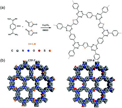
Herein, we designed and synthesized CTF-7 with a sulfur (S) heteroatom and CTF-8 with an oxygen (O) heteroatom using thiophene and furan as building blocks (Fig. 1). Sulfur is less electronegative than oxygen, and has a smaller ability to pull electrons than oxygen. The D–A system formed by thiophene and triazine units in CTF-7 belongs to the π-electron polarization distribution, while the D–A system formed by furan and triazine units in CTF-8 is assigned to the π-electron uniform distribution. It was found that the polarized distribution of the π-electron by the S heteroatom is more favorable for charge separation. The hydrogen evolution rate of CTF-7 can be up to 7430 μmol g−1 h−1 under visible light irradiation, which is about 5.6 times that of CTF-8.
 | ||
| Fig. 1 (a) Synthetic routes of CTF-7 and CTF-8 with thiophene and furan building blocks, respectively. (b) Structural representations of CTF-7 and CTF-8. | ||
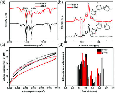
The two kinds of CTFs (CTF-7 and CTF-8) were synthesized using an aldehyde amidine condensation reaction under the conditions of feeding rate control.9 As shown in the Fourier-transformed infrared (FT-IR) spectra of CTF-7 and CTF-8 (Fig. 2a), the characteristic vibrations at 1517 cm−1 and 1354 cm−1 should be attributed to C![[double bond, length as m-dash]](https://www.rsc.org/images/entities/char_e001.gif) N stretching vibration and C–N stretching vibration of triazine units, respectively.10 From the solid-state cross-polarization magic angle spinning 13C nuclear magnetic resonance (CP-MAS 13C-NMR) spectra of CTF-7 (Fig. 2b), the chemical shifts at 169.6 ppm and 146.7 ppm should be ascribed to the sp2 carbon signal from triazine and α carbon signal from thiophene rings, respectively.11 Moreover, other peaks at around 138.3 and 128.5 ppm can be assigned to phenyl carbons. The calculated chemical shift of the β carbon from furan is about 127.6 ppm, which may be contained in the main peak at round 128.5 ppm. In the matter of CTF-8 (Fig. 2b), the peaks at 169.6 ppm, 138.3 and 128.5 ppm should be assigned to carbon signals from triazine and benzene rings, respectively.12 The other peaks at around 153.6 ppm and 118.2 ppm can be attributed to α carbon and β carbon of furan building blocks, respectively. The elemental analysis (EA) results indicate that the carbon, nitrogen, oxygen and sulphur contents are close to the theoretical values (Table S1, ESI†). X-ray photoelectron spectroscopy (XPS) analysis further confirmed the triazine formation of CTF-7 and CTF-8 (Fig. S1, ESI†).
N stretching vibration and C–N stretching vibration of triazine units, respectively.10 From the solid-state cross-polarization magic angle spinning 13C nuclear magnetic resonance (CP-MAS 13C-NMR) spectra of CTF-7 (Fig. 2b), the chemical shifts at 169.6 ppm and 146.7 ppm should be ascribed to the sp2 carbon signal from triazine and α carbon signal from thiophene rings, respectively.11 Moreover, other peaks at around 138.3 and 128.5 ppm can be assigned to phenyl carbons. The calculated chemical shift of the β carbon from furan is about 127.6 ppm, which may be contained in the main peak at round 128.5 ppm. In the matter of CTF-8 (Fig. 2b), the peaks at 169.6 ppm, 138.3 and 128.5 ppm should be assigned to carbon signals from triazine and benzene rings, respectively.12 The other peaks at around 153.6 ppm and 118.2 ppm can be attributed to α carbon and β carbon of furan building blocks, respectively. The elemental analysis (EA) results indicate that the carbon, nitrogen, oxygen and sulphur contents are close to the theoretical values (Table S1, ESI†). X-ray photoelectron spectroscopy (XPS) analysis further confirmed the triazine formation of CTF-7 and CTF-8 (Fig. S1, ESI†).
 | ||
| Fig. 2 (a) FT-IR spectra, (b) CP-MAS 13C-NMR spectra, (c) CO2 adsorption curves and (d) corresponding pore size distributions of CTF–7 (black) and CTF-8 (red) at 273 k. | ||
Based on the N2 adsorption isotherm, the surface areas of CTF-7 and CTF-8 calculated by the Brunauer–Emmett–Teller (BET) method were found to be 449 m2 g−1 and 5 m2 g−1, respectively (Fig. S2, ESI†). However, according to the CO2 adsorption isotherm, the BET surface areas of CTF-7 and CTF-8 were 384 m2 g−1 and 481 m2 g−1, respectively (Fig. 2c). The pore size distributions of CTF-7 and CTF-8 are concentrated at 0.45–0.85 nm and 0.52–0.81 nm, respectively (Fig. 2d). Due to the small pore sizes of CTF-7 and CTF-8, the smaller CO2 molecules are more suitable for porosity tests than N2 molecules. From the scanning electron microscopy (SEM) and transmission electron microscopy (TEM) images, it can be seen that CTF-7 is obviously a honeycomb morphology, while CTF-8 is a block morphology (Fig. S3a, b and S4a, b, ESI†). As shown in powder X-ray diffraction (PXRD) (Fig. S5, ESI†), both CTF-7 and CTF-8 are amorphous, despite a series of attempts under various conditions, which should be related to the planarity of monomers.3d,9,19 The order of aromaticity is benzene > thiophene > furan, which may affect the crystallinity orders of CTF-1, CTF-7 and CTF-8. Thermogravimetric analysis (TGA) reveals that both CTF-7 and CTF-8 can be stable up to about 470 °C under a nitrogen environment (Fig. S6, ESI†).
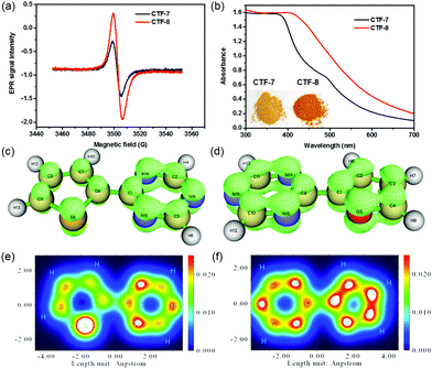
To analyze the O/S heteroatom effects of CTF-7 and CTF-8, the electron paramagnetic resonance (EPR) was employed to evaluate their unpaired electron intensities in the dark. As shown in Fig. 3a, the EPR signal intensity of CTF-8 was higher than that of CTF-7, indicating that the larger delocalized system of CTF-8 makes the distribution of the π electron in CTF-8 more symmetrical than that of CTF-7.7,13 The π electron distribution characteristics of CTF-7 and CTF-8 fragments were characterized by the isosurface map and colored map derived from Mulliken analysis.14 The isosurface map shows that the fragment of thiophene and triazine has a lower π electron density than that of the fragment of furan and triazine (Fig. 3c and d). The colored map can further make it clear that the π electron distribution of the thiophene fragment is not as uniform as that of the furan fragment because of the weaker electronegativity of sulfur than oxygen (Fig. 3e and f). Moreover, the color of CTF-8 is deeper than that of CTF-7 (inset of Fig. 3b). From the UV-visible spectra, it can be unequivocally observed that CTF-8 has higher light absorption than CTF-7 in the visible light region, suggesting that CTF-8 has a larger delocalized system than CTF-7 (Fig. 3b). Therefore, all results revealed that CTF-7 and CTF-8 are the π-electron polarization distribution structure and the π-electron uniform distribution, respectively.
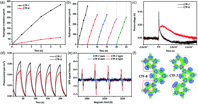
The properties of the O/S heteroatom of CTFs may affect the photocatalytic activity. We then evaluated the photocatalytic hydrogen evolution performance of CTFs loaded with 1 wt% Pd under visible light irradiation (λ > 420 nm) according to the literature.10a No hydrogen signal peaks were found by gas chromatography in the absence of light (Fig. S7, ESI†). The CTFs without Pd loading have low photocatalytic hydrogen evolution activity. The highest hydrogen evolution rate (HER) of CTF-7 without Pd loading is about 1530 μmol g−1 h−1 (Fig. S7, ESI†). After adding Pd as the cocatalyst, the HERs of CTF-7 and CTF-8 reach 7430 μmol g−1 h−1 and 1320 μmol g−1 h−1, respectively (Fig. 4a). Moreover, the HER of CTF-7 is about 5.6 times that of CTF-8, implying that CTF-7 with the S heteroatom has higher photocatalytic activity than CTF-8 with the O heteroatom. It is worth mentioning that the photocatalytic hydrogen evolution activity of CTF-7 with 1 wt% Pd is comparable to that of most of the porous organic polymers and inorganic materials in the literature (Table S2, ESI†). In order to examine the stability of CTF-7, a total of 5 photocatalytic cycles for about 25 h were measured (Fig. 4b). After five photocatalytic cycles, the HER of CTF-7 remains to be about 5320 μmol g−1 h−1, indicating good photocatalytic stability. In order to study the effect of catalyst dosage, a series of different amounts of CTF-7 samples were evaluated (Fig. S8, ESI†). The HERs are 9240 μmol g−1 h−1 for 5.0 mg, 7430 μmol g−1 h−1 for 10.0 mg and 4380 μmol g−1 h−1 for 20.0 mg, respectively. Due to the effect of the dosage of the catalyst on light absorption, the hydrogen evolution performance is not proportional to the dosage.7 From the XRD, XPS, SEM and TEM characterization, the structure and morphology of the recycled samples (Re-CTF-7 and Re-CTF-8) do not show much change in comparison to CTF-7 and CTF-8 (Fig. S1, S3, S4 and S9, ESI†).
Transient surface photovoltage (TSPV) measurements are widely used to understand the detailed charge separation dynamics, such as the separation direction, mode and efficiency, by analyzing the shape, time scale and intensity of the TSPV spectra.15,16 As shown in Fig. 4c, the photovoltage of CTF–7 is much higher than that of CTF–8, indicating that the carrier concentration of CTF–7 is higher than that of CTF-8.17 Noticeably, the charge separation time of CTF–7 (4.6 × 10⁻⁶ s) is shorter than that of CTF-8 (4.2 × 10⁻⁴ s), suggesting that CTF-7 is better for charge separation in comparison with CTF-8. In the steady-state PL spectra (Fig. S10, ESI†), the relative intensity of CTF-7 is higher than that of CTF-8. In the time-resolved PL spectra (Fig. S11, ESI†), the average lifetime of CTF-7 (1.10 ns) is longer than that of CTF-8 (0.96 ns), indicating that CTF-7 is better for the charge separation than CTF-8.18 Furthermore, as shown in the T–t curves (Fig. 4d), the photocurrent response of CTF-7 is significantly better than that of CTF-8. In Fig. 4e, the response intensity of DMPO-˙O2− in CTF-7 was much higher than that in CTF-8 under light irradiation, indicating that more electrons and holes are generated in CTF-7 under the same conditions. These results further confirmed that CTF-7 with the S heteroatom is more favorable for charge separation than CTF-8 with the O heteroatom.
To obtain insights into understanding the O/S heteroatom effects on charge separation in the photocatalytic processes, the electron density differences and the molecular orbitals were calculated using the Gaussian and Mulliken softwares. As shown in Fig. S12 (ESI†), the LUMO mostly localizes on the triazine, and the HOMO mostly localizes on the thiophene and furan units, which implies that the excited electrons will migrate from the thiophene and furan units to the triazine units. Based on the simulated electron density difference distribution (Fig. 4f), both the negative and positive areas of thiophene sulfur are larger than those of furan oxygen, suggesting that the excited electrons of sulfur heteroatoms migrate to triazine units more efficiently than oxygen heteroatoms in CTFs.
In summary, we designed and synthesized CTF-7 with sulfur heteroatoms and CTF-8 with oxygen heteroatoms through thiophene and furan building blocks, respectively. The hydrogen evolution rate of CTF-7 reaches 7430 μmol g−1 h−1 which is about 5.6 times that of CTF-8 (1320 μmol g−1 h−1). It was found that sulfur and oxygen heteroatoms lead to a polarized π electron distribution and a symmetric π electron distribution in CTFs, respectively. The polarized π electron distribution structure is more favourable for charge separation in CTFs.
This study was supported by the National Natural Science Foundation of China (Grant No. 52072327 and 21673200) and the Zhongyuan Thousand Talents (Zhongyuan Scholars) Program of Henan Province (202101510004).
Conflicts of interest
There are no conflicts to declare.References
- (a) X. Guan, F. Chen, Q. Fang and S. Qiu, Chem. Soc. Rev., 2020, 49, 1357–1384 RSC; (b) Y. Li, W. Chen, G. Xing, D. Jiang and L. Chen, Chem. Soc. Rev., 2020, 49, 2852–2868 RSC; (c) C. S. Diercks and O. M. Yaghi, Science, 2017, 355, eaal1585 CrossRef; (d) C. Xia, K. O. Kirlikovali, T. H. C. Nguyen, X. C. Nguyen, Q. B. Tran, M. K. Duong, M. T. Nguyen Dinh, D. L. T. Nguyen, P. Singh, P. Raizada, V.-H. Nguyen, S. Y. Kim, L. Singh, C. C. Nguyen, M. Shokouhimehr and Q. V. Le, Coord. Chem. Rev., 2021, 446, 214117 CrossRef CAS; (e) H. Wang, H. Wang, Z. Wang, L. Tang, G. Zeng, P. Xu, M. Chen, T. Xiong, C. Zhou, X. Li, D. Huang, Y. Zhu, Z. Wang and J. Tang, Chem. Soc. Rev., 2020, 49, 4135–4165 RSC; (f) X. Chen, K. Geng, R. Liu, K. T. Tan, Y. Gong, Z. Li, S. Tao, Q. Jiang and D. Jiang, Angew. Chem., Int. Ed., 2019, 59, 5050–5091 CrossRef.
- (a) J. M. Lee and A. I. Cooper, Chem. Rev., 2020, 120, 2171–2214 CrossRef CAS; (b) J. Kosco, M. Sachs, R. Godin, M. Kirkus, L. Francas, M. Bidwell, M. Qureshi, D. Anjum, J. R. Durrant and I. McCulloch, Adv. Energy Mater., 2018, 8, 1802181 CrossRef; (c) Y. Xu, S. Jin, H. Xu, A. Nagai and D. Jiang, Chem. Soc. Rev., 2013, 42, 8012–8031 RSC.
- (a) M. Liu, L. Guo, S. Jin and B. Tan, J. Mater. Chem. A, 2019, 7, 5153–5172 RSC; (b) C. Krishnaraj, H. S. Jena, K. Leus and P. Van Der Voort, Green Chem., 2020, 22, 1038–1071 RSC; (c) Z. Yang, H. Chen, S. Wang, W. Guo, T. Wang, X. Suo, D. E. Jiang, X. Zhu, I. Popovs and S. Dai, J. Am. Chem. Soc., 2020, 142, 6856–6860 CrossRef CAS PubMed; (d) M. Liu, Q. Huang, S. Wang, Z. Li, B. Li, S. Jin and B. Tan, Angew. Chem., Int. Ed., 2018, 57, 11968–11972 CrossRef CAS PubMed.
- (a) X. Wang, L. Chen, S. Y. Chong, M. A. Little, Y. Wu, W. H. Zhu, R. Clowes, Y. Yan, M. A. Zwijnenburg, R. S. Sprick and A. I. Cooper, Nat. Chem., 2018, 10, 1180–1189 CrossRef CAS; (b) S. Wei, F. Zhang, W. Zhang, P. Qiang, K. Yu, X. Fu, D. Wu, S. Bi and F. Zhang, J. Am. Chem. Soc., 2019, 141, 14272–14279 CrossRef PubMed.
- (a) X. Lan, X. Liu, Y. Zhang, Q. Li, J. Wang, Q. Zhang and G. Bai, ACS Catal., 2021, 11, 7429–7441 CrossRef CAS; (b) L. Chen, L. Wang, Y. Wan, Y. Zhang, Z. Qi, X. Wu and H. Xu, Adv. Mater., 2019, e1904433 Search PubMed.
- (a) L. Guo, Y. Niu, H. Xu, Q. Li, S. Razzaque, Q. Huang, S. Jin and B. Tan, J. Mater. Chem. A, 2018, 6, 19775–19781 RSC; (b) Z.-A. Lan, Y. Fang, Y. Zhang and X. Wang, Angew. Chem., 2018, 130, 479–483 CrossRef; (c) Z. A. Lan, M. Wu, Z. Fang, X. Chi, X. Chen, Y. Zhang and X. Wang, Angew. Chem., Int. Ed., 2021, 60, 16355–16359 CrossRef CAS.
- L. Guo, Y. Niu, S. Razzaque, B. Tan and S. Jin, ACS Catal., 2019, 9, 9438–9445 CrossRef CAS.
- (a) L. Y. Li, W. Fang, P. Zhang, J. H. Bi, Y. H. He, J. Y. Wang and W. Y. Su, J. Mater. Chem. A, 2016, 4, 12402–12406 RSC; (b) Y. J. Yang, A. Acharjya, M. Y. Ye, J. Rabeah, S. Li, Z. Kochovski, S. Youk, J. Roeser, J. Gruneberg, C. Penschke, M. Schwarze, T. Wang, Y. Lu, R. van de Krol, M. Oschatz, R. Schomacker, P. Saalfrank and A. Thomas, Angew. Chem., Int. Ed., 2021, 60, 19797–19803 CrossRef.
- M. Liu, K. Jiang, X. Ding, S. Wang, C. Zhang, J. Liu, Z. Zhan, G. Cheng, B. Li, H. Chen, S. Jin and B. Tan, Adv. Mater., 2019, 31, e1807865 CrossRef.
- (a) M. Liu, X. Wang, J. Liu, K. Wang, S. Jin and B. Tan, ACS Appl. Mater. Interfaces, 2020, 12, 12774–12782 CrossRef CAS PubMed; (b) K. Wang, L. M. Yang, X. Wang, L. Guo, G. Cheng, C. Zhang, S. Jin, B. Tan and A. Cooper, Angew. Chem., Int. Ed., 2017, 56, 14149–14153 CrossRef CAS; (c) S. Zhang, G. Cheng, L. Guo, N. Wang, B. Tan and S. Jin, Angew. Chem., Int. Ed., 2020, 59, 6007–6014 CrossRef CAS.
- (a) M. J. Bojdys, J. Jeromenok, A. Thomas and M. Antonietti, Adv. Mater., 2010, 22, 2202–2205 CrossRef CAS; (b) Y. Tang, H. Huang, B. Peng, Y. Chang, Y. Li and C. Zhong, J. Mater. Chem. A, 2020, 8, 16542–16550 RSC.
- S. Kuecken, A. Acharjya, L. Zhi, M. Schwarze, R. Schomacker and A. Thomas, Chem. Commun., 2017, 53(43), 5854–5857 RSC.
- L. Shi, K. Chang, H. Zhang, X. Hai, L. Yang, T. Wang and J. Ye, Small, 2016, 12, 4431–4439 CrossRef CAS PubMed.
- (a) L. U. Tian and C. Fei-Wu, Acta Phys.-Chim. Sin., 2011, 27, 2786–2792 Search PubMed; (b) T. Lu and Q. Chen, Theor. Chem. Acc., 2020, 139, 25 Search PubMed.
- F. Chen, T. Ma, T. Zhang, Y. Zhang and H. Huang, Adv. Mater., 2021, 33, e2005256 CrossRef PubMed.
- (a) B. Zhang, Y. Lei, R. Qi, H. Yu, X. Yang, T. Cai and Z. Zheng, Sci. China Mater., 2018, 62, 519–526 CrossRef; (b) Y. Lei, L. Gu, W. He, Z. Jia, X. Yang, H. Jia and Z. Zheng, J. Mater. Chem. A, 2016, 4, 5474–5481 RSC; (c) K. Lu, Y. Lei, R. Qi, J. Liu, X. Yang, Z. Jia, R. Liu, Y. Xiang and Z. Zheng, J. Mater. Chem. A, 2017, 5, 25211–25219 RSC.
- H. Wang, J. Jia, L. Wang, K. Butler, R. Song, G. Casillas, L. He, N. P. Kherani, D. D. Perovic, L. Jing, A. Walsh, R. Dittmeyer and G. A. Ozin, Adv. Sci., 2019, 6, 1902170 CrossRef CAS.
- Z. A. Lan, G. Zhang, X. Chen, Y. Zhang, K. A. I. Zhang and X. Wang, Angew. Chem., Int. Ed., 2019, 58, 10236–10240 CrossRef CAS.
- X. Chen, M. Addicoat, S. Irle, A. Nagai and D. Jiang, J. Am. Chem. Soc., 2013, 135, 546–549 CrossRef CAS.
Footnote |
| † Electronic supplementary information (ESI) available. See DOI: 10.1039/d1cc05619k |
| This journal is © The Royal Society of Chemistry 2022 |


