Janus bifunctional periodic mesoporous organosilica†
Majid
Vafaeezadeh
 *a,
Kristin
Weber
a,
Anna
Demchenko
b,
Philipp
Lösch
 c,
Paul
Breuninger
c,
Andrea
Lösch
c,
Paul
Breuninger
c,
Andrea
Lösch
 a,
Michael
Kopnarski
b,
Sergiy
Antonyuk
c,
Wolfgang
Kleist
 a and
Werner R.
Thiel
 *a
*a
aFachbereich Chemie, Technische Universität Kaiserslautern, Erwin-Schrödinger-Str. 54, Kaiserslautern 67663, Germany. E-mail: majidvafaeezadeh@yahoo.com; thiel@chemie.uni-kl.de
bInstitut für Oberflächen und Schichtanalytik (IFOS), Technische Universität Kaiserslautern, Trippstadter-Str. 120, Kaiserslautern 67663, Germany
cFachbereich Maschinenbau und Verfahrenstechnik Mechanische Verfahrenstechnik, Technische Universität Kaiserslautern, Gottlieb-Daimler-Str. 44, Kaiserslautern 67663, Germany
First published on 24th November 2021
Abstract
Synthesis of a Janus periodic mesoporous organosilica material (JPMO) is presented here. In this strategy, the surface of the hollow silica material was selectively functionalized with two different bridged organic–inorganic hybrid groups. It was found that the resulting bifunctional material is able to form a stable Pickering emulsion. This new type of PMO material may be suitable for widespread applications in various fields related to material science and catalysis.
Periodic mesoporous organosilicas (PMOs) are a class of organic–inorganic hybrid materials that offers a variety of applications in catalysis, as hosts for drugs and biomolecules, for adsorption, ion exchange, separation, for electronic and optical applications as well as for bioimaging.1 In PMOs, the organic groups are located as bridges between the silicon centers ((R′O)3Si-R-Si(OR′)3 (R′ = methyl or ethyl, R = bridging organic group)). They were first reported independently by Ozin and co-workers,2 Inagaki and co-workers3 and Stein and co-workers4 in 1999. In comparison to the traditional surface modified silica materials, PMOs offer an enhanced number of surface functionalities and allow an improved adjustment of the surface polarity. This is due to the complete coverage of the surface by functional groups, a more uniform organic group distribution and in consequence a reduced leaching of the active sites.1 Nevertheless, the preparation of bridged silane precursors for PMO synthesis, which can simultaneously provide suitable polarity and functionality while preserving the porosity of the resulting material is not simple at all.5 Consequently, in spite of the fascinating properties of PMOs,1 the accessibility of bifunctional PMOs is restricted to some extent. In an attempt to synthesize a bifunctional PMO catalyst, a Brønsted acid/base PMO was prepared in our group some years ago and employed in a deacetalization–nitroaldol cascade reaction.6 In the literature, there are further documentations that by a stringent control of the reaction conditions, PMOs with fascinating geometries such as multipodal7 or hollow shapes can be prepared.8
Janus materials are on the other side anisotropic functional particles consisting of two distinct faces with different physicochemical properties. They were popularized in 1991 by Pierre-Gilles de Gennes in his Nobel lecture9 and have attracted attentions in various fields of research.10 To date, different types of Janus materials based on silica,11 organic polymers,12 graphene13 and cellulose14 with interesting applications have been reported. Recently, we described a new strategy for the synthesis of heterogeneous Janus catalysts based on hollow spherical silica particles with tunable surface polarities and a rather simple synthetic procedure by employing cheap starting materials.15 However, despite some significant achievements, our previous methods suffered from a relatively long procedure and a fair selectivity for the immobilization of the second groups on the surface. Furthermore, the method was not employed for the synthesis of PMO materials. In addition, we described how organic reactions based on such Janus interphase catalysts could proceed via the formation of Pickering emulsions.16 The particles in the Pickering emulsion systems can be considered as temporary nano-/microreactors to carry out more environmentally friendly catalytic processes with high conversions and selectivities while still allowing the simple catalyst recovery by filtration.17
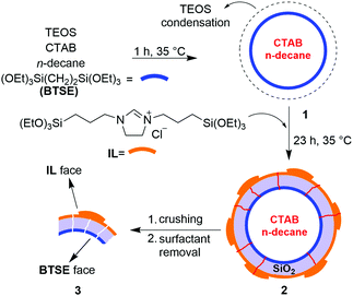
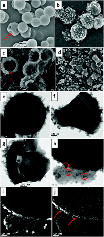
Accordingly, we herein wish to introduce a facile and one-pot procedure for the synthesis of a Janus periodic mesoporous organosilica (JPMO) by a selective surface bifunctionalization using a bridging organic precursor in combination with an imidazolinium-based ionic liquid (IL) precursor. The schematic process of the JPMO material's synthesis is shown in Scheme 1. The initial reaction mixture was prepared by the addition of an ethanol/n-decane solution to a flask containing H2O, cetyltrimethylammonium bromide (CTAB) and a 25% solution of ammonia in water. After ultrasonication of this solution, 1,2-bis(triethoxysilyl)ethane (BTSE) and tetraethyl orthosilicate (TEOS) were added to the reaction mixture, which was stirred at 35 °C for 1 h to form the initially hollow spherical particles 1. Then, an ethanolic solution of the ionic liquid (IL) precursor was added dropwise to the solution and the condensation reaction was continued for 23 h. At the end of the reaction, the material was separated by centrifugation, dried in an oven and then crushed followed by removing of the surfactant (see the ESI† for experimental details). The elemental analysis (CHN) of material 3 revealed that the loading of the IL layer is 0.90 mmol g−1. Scanning electron microscopy (SEM) images following the preparation steps leading to JPMO 3 are shown in Fig. 1. The structure of the hollow material containing BTSE in the absence of the IL precursor shows a smooth external surface (Fig. 1a). The presence of some wrinkled particles is an evidence for formation of the hollow geometry. The image of the hollow JPMO 2 decorated with the IL precursor is shown in Fig. 1b. The rough outer surface of the particles containing the IL layer is clearly observable. Fig. 1c provides the structure of JPMO 2 in the middle time of the crushing process. As can be deduced from a cross-section demonstration, the IL face is uneven, while the inner face with the BTSE groups (red arrow) remains smooth. Thus, this image proves the selective preparation of two anisotropic faces. Crushing of the JPMO 2 spheres leads to the formation of nano size bent sheets (Fig. 1d). Transmission electron microscopy (TEM) analysis also revealed the hollow geometry of JPMO 2 (Fig. 1e) surrounded by the corona-like IL layer. The uneven IL face (Fig. 1f) and the flat BTSE face (Fig. 1g) of the JPMO 3 nanosheets are clearly distinguishable in the TEM images. These TEM images (Fig. 1f versus g) also prove the mechanical stability of the IL layer in JPMO 3 material even during the crushing process. The selective surface functionalization was further investigated by labelling of the half-crushed JPMO 3 by mixing it with negatively charged citrate-capped Fe3O4 nanoparticles (Fe3O4@citrate) as described before.15b–d During the labelling, the outer IL surface of the material with ionic characteristics strongly interacts with the labelling agent and becomes rough while the relatively inert inner BTSE-functionalized surface remains untouched (Fig. 1h and Fig. S1, ESI†). Elemental mapping analysis confirmed the presence of iron (Fe) nanoparticles on the outer surface (Fig. 1i). In addition, elemental mapping of chloride (counter anion of the IL) proved the mentioned corona-like IL layer on the external face of the material (Fig. 1j). The N2 adsorption–desorption isotherms of materials 2 and 3 show type-IV profiles, which are typical for mesoporous materials (Fig. S2, ESI†). From these measurements, the specific surface area and the pore volume of JPMO 2 were found to be 528 m2 g−1 and 0.43 mL g−1, respectively. In our previous reports15 we showed that during the crushing of the hollow Janus materials, some mesopores can be destroyed leading to a decrease of both parameters.
Interestingly, the above mentioned surface parameters for the crushed JPMO 3 show increased values of 699 m2 g−1 and 0.59 mL g−1, respectively. A plausible explanation for the decreased surface area and pore volume of JPMO 2 compared to JPMO 3 might be found in the formation of the IL layer on the external surface of the hollow material, which might block some pores and partially prevent the penetration of N2. After crushing the material, the inner free ends of the pores might be better accessible and hence the observed surface area and pore volume of the crushed material is higher than the uncrushed one. On the other hand, the BJH average pore diameters of materials 2 and 3 were found to be nearly identical by 3.22 and 3.15 nm, respectively.
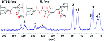
The solid-state 13C CP-MAS NMR spectrum of JPMO 3 is shown in Fig. 2. All peaks in this spectrum can be assigned to the corresponding carbon atoms of IL and BTSE. The resonances of the carbon atoms C1 and C4, which are connected to the silicon atoms and therefore are more shielded, appear at 4.3 and 8.2 ppm. The signals of the atoms C2 and C3 belonging to the ethoxy groups in BTSE and IL are observed at 17.2 and 58.1 ppm. The rest of the signals are originating from IL and all of them can be assigned properly. In the solid-state 29Si CP-MAS NMR spectrum of JPMO 3 (Fig. S4, ESI†) there are the two dominant resonances of the silica framework centers Q3 [Si(OSi)3OH] and Q4 [Si(OSi)4] at around −104 and −113 ppm. The presence of T2 [RSi(OSi)2(OH)] (−59 ppm) and T3 [RSi(OSi)3] (−67 ppm) resonances as two broad signals provides an additional evidence for the successful covalent immobilization of the BTSE and IL precursors on the surface of the materials.
 | ||
| Fig. 2 Solid-state 13C CP-MAS NMR spectrum of JPMO 3. The asterisk * refer to the background peaks of the NMR tube. The dashed line reflects the symmetry in the IL molecule. | ||
Due to the orthogonal polarities of the faces of the material, the possibility of JPMO 3 to undergo the formation of a Pickering emulsion was studied. The pictures of material 3 in a solvent system comprising of water and toluene are shown in Fig. 3. At the beginning of the mixing, a uniform Pickering emulsion was formed with the two solvents, which was stable up to one day (Fig. 3a). The emulsion type can be adjusted by the alteration of the water![[thin space (1/6-em)]](https://www.rsc.org/images/entities/char_2009.gif) :
:![[thin space (1/6-em)]](https://www.rsc.org/images/entities/char_2009.gif) oil (w
oil (w![[thin space (1/6-em)]](https://www.rsc.org/images/entities/char_2009.gif) :
:![[thin space (1/6-em)]](https://www.rsc.org/images/entities/char_2009.gif) o) volume ratio (Fig. 3b–d): at a w
o) volume ratio (Fig. 3b–d): at a w![[thin space (1/6-em)]](https://www.rsc.org/images/entities/char_2009.gif) :
:![[thin space (1/6-em)]](https://www.rsc.org/images/entities/char_2009.gif) o ratio of 1
o ratio of 1![[thin space (1/6-em)]](https://www.rsc.org/images/entities/char_2009.gif) :
:![[thin space (1/6-em)]](https://www.rsc.org/images/entities/char_2009.gif) 5, the emulsion is a water-in-oil type (Fig. 3b) and it is located at the bottom of the vial. The emulsion persisted in the middle of the water/toluene phases (after two days) when the w
5, the emulsion is a water-in-oil type (Fig. 3b) and it is located at the bottom of the vial. The emulsion persisted in the middle of the water/toluene phases (after two days) when the w![[thin space (1/6-em)]](https://www.rsc.org/images/entities/char_2009.gif) :
:![[thin space (1/6-em)]](https://www.rsc.org/images/entities/char_2009.gif) o ratio was 1
o ratio was 1![[thin space (1/6-em)]](https://www.rsc.org/images/entities/char_2009.gif) :
:![[thin space (1/6-em)]](https://www.rsc.org/images/entities/char_2009.gif) 1 (Fig. 3c). Finally at a w
1 (Fig. 3c). Finally at a w![[thin space (1/6-em)]](https://www.rsc.org/images/entities/char_2009.gif) :
:![[thin space (1/6-em)]](https://www.rsc.org/images/entities/char_2009.gif) o ratio of 5
o ratio of 5![[thin space (1/6-em)]](https://www.rsc.org/images/entities/char_2009.gif) :
:![[thin space (1/6-em)]](https://www.rsc.org/images/entities/char_2009.gif) 1, an oil-in-water emulsion floats at the upper side (Fig. 3d). These observations are in good agreement with the findings of Liang et al. for stabilizing emulsions with Janus particles.11m Interestingly, we found that commercial silica gel particles modified with BTSE and IL formed almost no Pickering emulsion and the material was deposited after 60 min (Fig. 3e). In addition, an un-functionalized crushed hollow material was found to be dispersed in both phases without the formation of a noticeable Pickering emulsion (Fig. 3f). On the other hand, the material with only BTSE functionalities on the inner face could mainly be dispersed in the organic phase (Fig. 3g). These observations indicate that the presence of BTSE and IL on opposite faces of the nanosheets is necessary for the formation of a desirable Pickering emulsion. The related experimental details are summarized in Fig. S8, ESI.† To study the behavior of JPMO 3 in the Pickering emulsion system in more detail, deposition analyses of JPMO 3 in water, toluene and a water/toluene mixture were performed using a sedimentation analyzer apparatus. The analysis in toluene showed a deposition of the material at a rotational speed of 200 rpm after 30 s (Fig. S5, ESI†). On the other hand, the deposition time of the material in water was found to be 55 s at 200 rpm (Fig. S6, ESI†). However, the behaviour of the JPMO 3 material in a Pickering emulsion containing water/toluene mixture is completely different from the single solvents.
1, an oil-in-water emulsion floats at the upper side (Fig. 3d). These observations are in good agreement with the findings of Liang et al. for stabilizing emulsions with Janus particles.11m Interestingly, we found that commercial silica gel particles modified with BTSE and IL formed almost no Pickering emulsion and the material was deposited after 60 min (Fig. 3e). In addition, an un-functionalized crushed hollow material was found to be dispersed in both phases without the formation of a noticeable Pickering emulsion (Fig. 3f). On the other hand, the material with only BTSE functionalities on the inner face could mainly be dispersed in the organic phase (Fig. 3g). These observations indicate that the presence of BTSE and IL on opposite faces of the nanosheets is necessary for the formation of a desirable Pickering emulsion. The related experimental details are summarized in Fig. S8, ESI.† To study the behavior of JPMO 3 in the Pickering emulsion system in more detail, deposition analyses of JPMO 3 in water, toluene and a water/toluene mixture were performed using a sedimentation analyzer apparatus. The analysis in toluene showed a deposition of the material at a rotational speed of 200 rpm after 30 s (Fig. S5, ESI†). On the other hand, the deposition time of the material in water was found to be 55 s at 200 rpm (Fig. S6, ESI†). However, the behaviour of the JPMO 3 material in a Pickering emulsion containing water/toluene mixture is completely different from the single solvents.
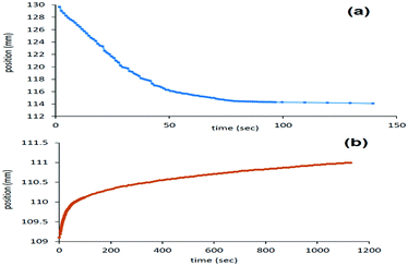
In the water/toluene system no noticeable deposition was observed at 200 rpm (Fig. S7, ESI†), which indicates the high stability of the Pickering emulsion. By increasing the centrifuging speed to 500 rpm, two different modes of separation, particle sedimentation and a parallel creaming (upward motion) were observed. The first diagram describes the creaming of the particles in the continuous water phase towards the interface of the solvents, which ended at the position 114 mm (Fig. 4a). The second deposition diagram belongs to the movement of the particles from top to the bottom within the continuous toluene phase, which ended at the position 111 mm (Fig. 4b). This indicates that at the end of the analysis, the material was stabilized at an interface of the solvents with a thickness of 3 mm. It is worth to note here that the creaming-up of the particles in the water phase was faster than the sedimentation inside the toluene in the biphasic system. This might be explained by the density differences between JPMO 3 on one side and of the solvents on the other side.
In summary, a simple and efficient method for the selective synthesis of a Janus-type bifunctional PMO material was reported. In addition to the benefits arising from the “bi-functionality” of the material, it was shown that the JPMO is able to form a Pickering emulsion, which allows several potential applications in catalysis, biological science, drug delivery or use as a heterogeneous surfactant in the future. Further developments and applications of JPMOs in particular concerning their catalytic activities in Pickering emulsion systems are ongoing research in our group.
Conflicts of interest
There are no conflicts to declare.Notes and references
- C. Ha and S. S. Park, Periodic Mesoporous Organosilicas: Preparation, Properties and Applications, Springer, Singapore, 2019 DOI:10.1007/978-981-13-2959-3.
- T. Asefa, M. J. MacLachlan, N. Coombs and G. A. Ozin, Nature, 1999, 402, 867–871 CrossRef CAS.
- S. Inagaki, S. Guan, Y. Fukushima, T. Ohsuna and O. Terasaki, J. Am. Chem. Soc., 1999, 121, 9611–9614 CrossRef CAS.
- B. J. Melde, B. T. Holland, C. F. Blanford and A. Stein, Chem. Mater., 1999, 11, 3302–3308 CrossRef CAS.
- (a) B. Karimi, D. Elhamifar, J. H. Clark and A. J. Hunt, Chem. – Eur. J., 2010, 16, 8047–8053 CrossRef CAS PubMed; (b) L. Wang, S. Shylesh, D. Dehe, T. Philippi, G. Dörr, A. Seifert, Z. Zhou, M. Hartmann, R. N. K. Taylor, M. Jia, S. Ernst and W. R. Thiel, ChemCatChem, 2012, 4, 395–400 CrossRef CAS; (c) B. Karimi, M. Khorasani, H. Vali, C. Vargas and R. Luque, ACS Catal., 2015, 5, 4189–4200 CrossRef CAS; (d) W. Huybrechts, J. Lauwaert, A. De Vylder, M. Mertens, G. Mali, J. W. Thybaut, P. Van Der Voort and P. Cool, Microporous Mesoporous Mater., 2017, 251, 1–8 CrossRef CAS; (e) J. Xu, T. Cheng, K. Zhang, Z. Wang and G. Liu, Chem. Commun., 2016, 52, 6005–6008 RSC; (f) B. Karimi, M. Khorasani, H. Vali and R. Luque, J. Mater. Chem. A, 2015, 3, 6575–6585 RSC; (g) J. Wang, Y. Zou, Y. Sun, M. Hemgesberg, D. Schaffner, H. Gao, X. Song, W. Zhang, M. Jia and W. R. Thiel, Chin. J. Catal., 2014, 35, 532–539 CrossRef CAS.
- S. Shylesh, A. Wagener, A. Seifert, S. Ernst and W. R. Thiel, Angew. Chem., Int. Ed., 2010, 49, 184–187 CrossRef CAS PubMed.
- (a) J. Croissant, X. Cattoën, M. W. C. Man, P. Dieudonné, C. Charnay, L. Raehm and J. Durand, Adv. Mater., 2015, 27, 145–149 CrossRef CAS; (b) J. G. Croissant, Y. Fatieiev, H. Omar, D. H. Anjum, A. Gurinov, J. Lu, F. Tamanoi, J. I. Zink and N. M. Khashab, Chem. – Eur. J., 2016, 22, 9607–9615 CrossRef CAS PubMed.
- (a) N. Ma, Y. Deng, W. Liu, S. Li, J. Xu, Y. Qu, K. Gan, X. Sun and J. Yang, Chem. Commun., 2016, 52, 3544–3547 RSC; (b) Z. Teng, W. Li, Y. Tang, A. Elzatahry, G. Lu and D. Zhao, Adv. Mater., 2019, 31, 1707612 CrossRef.
- P.-G. D. Gennes, Rev. Mod. Phys., 1992, 64, 645–648 CrossRef.
- (a) Z. Wu, L. Li, T. Liao, X. Chen, W. Jiang, W. Luo, J. Yang and Z. Sun, Nano Today, 2018, 22, 62–82 CrossRef CAS; (b) A. Walther and A. H. E. Müller, Chem. Rev., 2013, 113, 5194–5261 CrossRef CAS PubMed; (c) G. Agrawal and R. Agrawal, ACS Appl. Nano Mater., 2019, 2, 1738–1757 CrossRef CAS; (d) A. Kirillova, C. Marschelke and A. Synytska, ACS Appl. Mater. Interfaces, 2019, 11, 9643–9671 CrossRef CAS; (e) Y. Ye, J. Luan, M. Wang, Y. Chen, D. A. Wilson, F. Peng and Y. Tu, Chem. – Eur. J., 2019, 25, 8663–8680 CrossRef CAS; (f) X. Pang, C. Wan, M. Wang and Z. Lin, Angew. Chem., Int. Ed., 2014, 53, 5524–5538 CrossRef CAS PubMed; (g) X. Chen, G. Li, Q. Han, X. Li, L. Li, T. Wang and C. Wang, Chem. – Eur. J., 2017, 23, 17204–17208 CrossRef CAS PubMed.
- (a) S. Yan, H. Zou, S. Chen, N. Xue and H. Yang, Chem. Commun., 2018, 54, 10455–10458 RSC; (b) X. Kong, C. Wu, L. Feng, J. Qu, P. Liu, X. Wang and X. Zhang, Chem. Commun., 2017, 53, 8054–8057 RSC; (c) Y. Liu, F. Liang, Q. Wang, X. Qu and Z. Yang, Chem. Commun., 2015, 51, 3562–3565 RSC; (d) B. Liu, C. Zhang, J. Liu, X. Qu and Z. Yang, Chem. Commun., 2009, 3871–3873 RSC; (e) C. Wu, Z. Deng, B. Shang, O. Ikkala and B. Peng, Chem. Commun., 2018, 54, 12726–12729 RSC; (f) L. Zhang, F. Zhang, W. Dong, J. Song, Q. Huo and H. Sun, Chem. Commun., 2011, 47, 1225–1227 RSC; (g) X. Ji, Q. Zhang, F. Liang, Q. Chen, X. Qu, C. Zhang, Q. Wang, J. Li, X. Song and Z. Yang, Chem. Commun., 2014, 50, 5706–5709 RSC; (h) M. Zhang, Z. Tang, W. Fu, W. Wang, R. Tan and D. Yin, Chem. Commun., 2019, 55, 592–595 RSC; (i) F. Liang, J. Liu, C. Zhang, X. Qu, J. Li and Z. Yang, Chem. Commun., 2011, 47, 1231–1233 RSC; (j) L. Zhao, L. Zhu, Y. Chen, Q. Wang, J. Li, C. Zhang, F. Liang, X. Qu and Z. Yang, Chem. Commun., 2013, 49, 6161–6163 RSC; (k) F. Liang, K. Shen, X. Qu, C. Zhang, Q. Wang, J. Li, J. Liu and Z. Yang, Angew. Chem., Int. Ed., 2011, 50, 2379–2382 CrossRef CAS; (l) X. Zuo, M. Zhang, Q. Wu, Y. Li, G. Zhang, F. Liang and Z. Yang, Chem. Commun., 2021, 57, 5834–5837 RSC; (m) D. Sun, Y. Si, X. Song, F. Liang and Z. Yang, Chem. Commun., 2019, 55, 4667–4670 RSC; (n) L. Xia, H. Zhang, Z. Wei, Y. Jiang, L. Zhang, J. Zhao, J. Zhang, L. Dong, E. Li, L. Ruhlmann and Q. Zhang, Chem. – Eur. J., 2017, 23, 1920–1929 CrossRef CAS PubMed.
- (a) L. Zhang, S. Shi, G. Zhang, X. Song, D. Sun, F. Liang and Z. Yang, Chem. Commun., 2020, 56, 10497–10500 RSC; (b) F. Tu and D. Lee, Chem. Commun., 2014, 50, 15549–15552 RSC.
- (a) K. Yuan, Y. Li, X. Huang, Y. Liang, Q. Liu and G. Jiang, Chem. Commun., 2019, 55, 4957–4960 RSC; (b) H. Lee, K. Choi, J. Choi, J. Yoo, Y. Seo, S. Satija and J. Koo, ACS Appl. Nano Mater., 2019, 2, 4203–4210 CrossRef CAS; (c) A. Kouloumpis, D. D. Chronopoulos, G. Potsi, M. Pykal, J. Vlček, M. Scheibe and M. Otyepka, Chem. – Eur. J., 2020, 26, 6518–6524 CrossRef CAS PubMed.
- D. Li, J. Jiang and C. Cai, Chem. Commun., 2020, 56, 9396–9399 RSC.
- (a) M. Vafaeezadeh, P. Breuninger, P. Lösch, C. Wilhelm, S. Ernst, S. Antonyuk and W. R. Thiel, ChemCatChem, 2019, 11, 2304–2312 CrossRef CAS; (b) M. Vafaeezadeh, C. Wilhelm, P. Breuninger, S. Ernst, S. Antonyuk and W. R. Thiel, ChemCatChem, 2020, 12, 2695–2701 CrossRef CAS; (c) M. Vafaeezadeh, J. Schaumlöffel, A. Lösch, A. De Cuyper and W. R. Thiel, ACS Appl. Mater. Interfaces, 2021, 13, 33091–33101 CrossRef CAS; (d) M. Vafaeezadeh, R. Saynisch, A. Lösch, W. Kleist and W. R. Thiel, Molecules, 2021, 26, 6450 CrossRef CAS.
- M. Vafaeezadeh and W. R. Thiel, J. Mol. Liq., 2020, 315, 113735 CrossRef CAS.
- (a) J. Yang, J. Wang, Y. Liu, H. Li and Z. Lin, Mater. Horiz., 2020, 7, 3242–3249 RSC; (b) A. M. B. Rodriguez and B. P. Binks, Soft Matter, 2020, 16, 10221–10243 RSC; (c) F. Chang, C. M. Vis, W. Ciptonugroho and P. C. A. Bruijnincx, Green Chem., 2021, 23, 2575–2594 RSC.
Footnote |
| † Electronic supplementary information (ESI) available. See DOI: 10.1039/d1cc06086d |
| This journal is © The Royal Society of Chemistry 2022 |


