
Thermostable water reservoirs in the interlayer space of a sodium hectorite clay through the intercalation of γ-aminopropyl(dimethyl)ethoxysilane in toluene†
Waldemar
Keil
 ,
Kai
Zhao
,
Arthur
Oswald
,
Wolfgang
Bremser
,
Claudia
Schmidt
and
Horst
Hintze-Bruening
*
,
Kai
Zhao
,
Arthur
Oswald
,
Wolfgang
Bremser
,
Claudia
Schmidt
and
Horst
Hintze-Bruening
*
Paderborn University, Department of Chemistry, Warburger Str. 100, 33098 Paderborn, Germany. E-mail: hhb@mail.upb.de
First published on 8th December 2021
Abstract
Treatment of Na+-based hectorite LAPONITE® (LAP) and of Na+-montmorillonite (MMT) with a homologous series of γ-aminopropyl(methyl)x(ethoxy)ysilanes (x + y = 3, y > 0) in toluene was studied by means of thermogravimetric analysis coupled with mass spectrometry, infrared spectroscopy, 29Si and 23Na solid-state nuclear magnetic resonance spectroscopy and powder X-ray diffraction. The triethoxy silane (APTS) exclusively grafts on the clays' edges as branched oligomers whereas both the monoethoxy silane (APMS) and the diethoxy silane (APDS) are also intercalated, the latter as linear oligomers. Intercalation of APMS varies for MMT and LAP: MMT hosts the smallest amounts of the silanes with marginal increase of the basal distance and no stabilization of water. On the contrary, LAP accommodates the largest amount of guests in the form of monomeric APMS which yields the largest increase of the basal distance and stabilizes water up to 200 °C when APMS dimerizes. APMS stabilization is attributed to intramolecular Si–O–H–NH2 hydrogen bonds and the hydrophobic geminal methyl groups together with the trimethylene sides of the cyclic monomers are thought to compartmentalize the hydrated sodium sites. The high temperature release of water from APMS@LAP is discussed in the light of potentially triggered interphase degradation in composite materials for recycling purposes.
1 Introduction
Since the Japanese automobile manufacturer Toyota successfully developed montmorillonite (MMT) containing nylon nanocomposites in 1987 and used them in automobile bumpers,1 much research has been carried out on polymer nanocomposites based on layered clay materials.2–8 The popularity of the latter is rooted in their capability to swell and exfoliate in an appropriate solvent, which enables a huge interfacial area between the individual layers and the polymer matrix.9,10 Clay minerals often exhibit a high aspect ratio, meaning that the lateral size is much larger than the layer thickness. Moreover, many clays are abundant minerals and their geological deposits are relatively easy to access. However, purification from accompanying minerals, e.g., iron oxide or silica, may limit their suitability for applications with high standards regarding optical and electromagnetic properties. Therefore, synthetic clays with tunable compositions such as LAPONITE® (LAP), commercialized since the 1960s, have gained attention.11 Here, MMT and LAP, whose structures are illustrated in Fig. 1a, are scrutinized. Both belong to the smectite group of phyllosilicates, where a central sheet of two- or three-valent metal-based oxide-hydroxides (edge-sharing octahedra) is covalently connected on both sides with a sheet of silica tetrahedra, each of them being connected with three neighbors. To counterbalance the higher charge of Al(III) one third of the octahedral sites are lacunae in MMT. Isomorphous substitution of M(III) and M(II) by M(II) and M(I), respectively, induces a net negative charge of the layers, which is compensated by intercalated cations. The chemical formulae of montmorillonite and LAPONITE® are| Na0.33{Al1.67Mg0.33(OH)2[Si4O10]}·nH2O for MMT |
| Na0.37{Mg2.75Li0.2(OH)2[Si4O10]}·nH2O for LAP. |
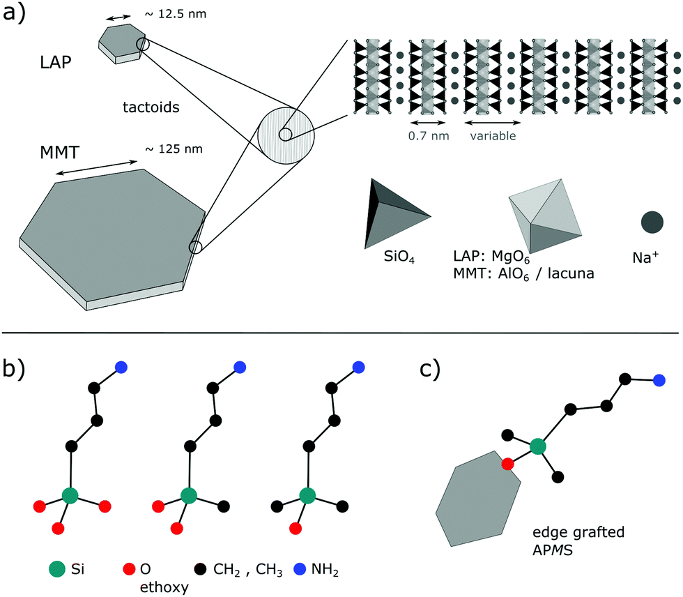 | ||
| Fig. 1 (a) Tactoids of LAP and MMT of unknown thicknesses and side view of stacked layers, each composed of two silica sheets that are sandwiching the metal oxide(hydroxide) sheet. Hydration amount of intercalated sodium cations (H2O not shown) determines the basal distance. (b) Homologous series of applied silanes (ethyl groups and H-atoms omitted). (c) Exemplary grafted silane on the edge of a single clay layer. Sketches are not true to scale. | ||
Even with relatively low clay loadings the inorganic particles may significantly improve mechanical, thermal and electrical properties of the polymer.3,14–18 For the preparation of polymer-clay nanocomposites, organic cations such as long hydrocarbon chains comprising quaternary ammonium ions are usually exchanged for sodium in order to render the clay surface compatible with the organic matrix and thus enable exfoliation of the clay.
However, it is generally assumed in the community that interfacial covalent bonding further increases strength and resistance towards solvents.19–21 In that respect, organic alkoxy- or chlorosilanes have received much attention.22 Besides the reaction with the clay surface or rim via hydrolysis of the silanes' Si-alkoxy or Si–Cl bond, a further, different functional group of the Si-alkyl moiety can be adapted for the reaction with the chosen polymer or its monomers for an in situ polymer synthesis, respectively.
Numerous works were devoted to the grafting23–27 on pristine LAP and MMT and different aspects have been investigated,26–28 such as the impact of the silane concentration, the role of the solvent, and the reaction conditions on the physical and chemical properties of the silylated clays. The latter have been attributed to different molecular arrangements of the intercalated silanes.29–31 Besides intercalation, grafting on Si–OH and Al(Mg)–OH groups at the rims of the layers (Fig. 1c) can occur.
However, for the reaction in nonpolar solvents like toluene intercalation is rarely observed. Herrera et al. investigated the silyation of LAP with a mono- versus a trialkoxy methacrylate functional silane32 whereas Daniel et al.33 studied the effect of the reaction conditions of the silylation of LAP with dimethylmethoxy-n-octylsilane. In neither case intercalation could be detected with X-ray diffraction (XRD).
Due to the variety of used materials and reaction conditions it is difficult to precisely predict the character of a reaction product of a given system from the published data. This also pertains to γ-aminopropyl bearing alkoxysilanes which were reacted in organic solvent with LAP and/or MMT.34,35
Here, the reactions of LAP as well as of MMT in toluene at ambient conditions with γ-aminopropyl bearing silanes of the homologous series
| NH2–(CH2)3–Si(CH3)x(OC2H5)3−x, x = 0,1,2 |
2 Experimental
2.1 Chemicals
Toluene (≥99.5%) was purchased from Merck and used without further purification. Na+-LAPONITE® (“LAPONITE® RD”) and Na+-montmorillonite (“Cloisite-Na+”) were donated by BYK-Chemie GmbH. 3-Aminopropyldimethylethoxysilane (APMS) (95%), 3-aminopropylmethyldiethoxysilane (APDS) (97%) and 3-aminopropyltriethoxysilane (APTS) (97%) were purchased from Sigma Aldrich. These materials were used as received.2.2 Grafting of amino-silanes on LAP and MMT
5 g of either LAPONITE® (LAP) or montmorillonite (MMT) were dispersed in 500 ml toluene in a round-bottom flask. Then, 3.7 mmol silane per g of clay were added, corresponding to 3.00 g APMS, 3.90 g APDS and 3.20 g APTS, respectively. The mixture was stirred with a magnetic stirrer under ambient conditions for four days. The grafted sample was collected after centrifugation at 7000 rpm (BECKMAN COULTER Avanti J-E with a JA-10 rotor). Then, the sediment was redispersed in 70 mL toluene by magnetic stirring for 10 min, ultrasonicated for 5 min (BANDELIN SONOCOOL 255, ultrasonic frequency 35 kHz) and finally collected again by centrifugation at 7000 rpm for 15 minutes. This process was repeated another three times in order to remove the excess of unreacted and self-condensed silane molecules. In a last step, the products were dried at 120 °C for 12 h in an oven. Samples were stored under ambient conditions before characterization. In addition, the sample APMS@LAP was annealed at 200 °C for 12 h in an oven in order to obtain information about the thermal stability of intercalated APMS.2.3 Characterization
7Li, 23Na, 27Al and 29Si magic angle spinning nuclear magnetic resonance (MAS-NMR) measurements were carried out at 25 °C using a Tecmag Apollo spectrometer equipped with a wide-bore 300 MHz Oxford magnet. The resonance frequencies of 7Li, 23Na, 27Al, and 29Si were 116.52 MHz, 79.30 MHz, 78.12 MHz, and 59.56 MHz respectively. Bruker MAS probes for rotors with a diameter of 4 and 7 mm were used; the spinning frequency varied between 3 and 10 kHz. Time-domain signals were recorded after single pulse excitation and under 1H decoupling. Typically, recycling delays of 5 s were used for 7Li, 23Na, and 27Al data acquisition, while a recycling delay of 15 s was used for 29Si data acquisition. The duration of the excitation pulses varied from 2–2.5 μs throughout all experiments. The signal of LiCl in D2O at 0 ppm, the signal of NaCl in D2O at 0 ppm, the Al(H2O)6Cl3 signal at 0 ppm and the OSi(CH3)3 signal of Q8M8 at 11.5 ppm were used as external chemical shift references for 7Li, 23Na, 27Al, and 29Si, respectively. The error of the chemical shifts reported is estimated as ±0.1 ppm. The principal values of the 29Si chemical shift tensors were estimated from spinning-sideband patterns by means of a Herzfeld-Berger analysis (HBA)36 using the software HBA 1.7.5 by Eichele.37Thermogravimetric analysis (TGA) was conducted using a Mettler-Toledo TGA/SDTA 851e instrument. Samples were heated from 25 to 1000 °C with a heating rate of 20 °C min−1, using synthetic air with a gas flow of 85 mL min−1. In some cases samples did not reach a plateau above 800 °C due to issues with base line stabilization. For the sake of comparability all shown data were obtained with the same set-up and found to be reproducible.
FTIR measurements were performed on the prepared powders in the ATR mode, using a Bruker Vertex 70 FTIR spectrometer (resolution 2 cm−1).
Powder X-ray diffraction (XRD) experiments were carried out on a Bruker AXS D8 Advance diffractometer using monochromatic Cu-Kα1 radiation (40 kV, 40 mA, λ = 1.5406 Å). The step size for small-angle measurements was 2θ = 0.0075° with a 3 s counting time for each step.
Energy dispersive X-ray spectroscopy (EDX) images were recorded using a Zeiss NEON 40 scanning electron microscope with an UltraDry detector by Thermo Fisher Scientific. EDX images were recorded with an acceleration voltage of 13 kV and an aperture size of 120 μm. The high-current mode was used to obtain EDX images.
Zeta-potential measurements were performed on a Malvern Zetasizer Nano ZS. The samples were prepared by dispersing 1 to 2 mg of clay in 4 g deionized water by ultrasonication. The dispersions were measured in a disposable, U-shape folded capillary cell by Malvern.
3 Results and discussion
Silylation of natural clays is often conducted in aqueous phase with the intention to take advantage of the distinct swellability of the layered material. However, the hydrolysis rate of silanes is promoted by the high concentration of water. Therefore, in the present study, toluene was used as solvent in order to limit quick hydrolysis and self-condensation of the silanes. This necessitates to add samples of the clays that were treated ceteris paribus in the absence of silane as reference: deh-LAP and deh-MMT. The untreated clays will be referred to as pristine clays. In analogy to hydration and dehydration of other Na-, Ca- and Ba-comprising montmorillonites38,39 it is expected that toluene dehydrates the interlayer space, which marginalizes the sodium hydration sphere, modifies the stacking order40 and decreases the basal distance of the layers.41 However, to the best of our knowledge, no XRD data have been published for samples that were treated like deh-LAP and deh-MMT. We note that the degree of swelling by the solvent and the reaction product ethanol in the dispersed state during silylation is unknown.3.1 Silylation products
In order to quantify the silylation yield, TGA has been carried out. Fig. 2 shows the dTGA curves of the pristine clays, the deh-clays and the silylated species. The corresponding TGA traces are given in the ESI† (Fig. S1) as well as the mass spectra which trace water, carbon dioxide, toluene and fragmentation products (Fig. S2 and S3, ESI†).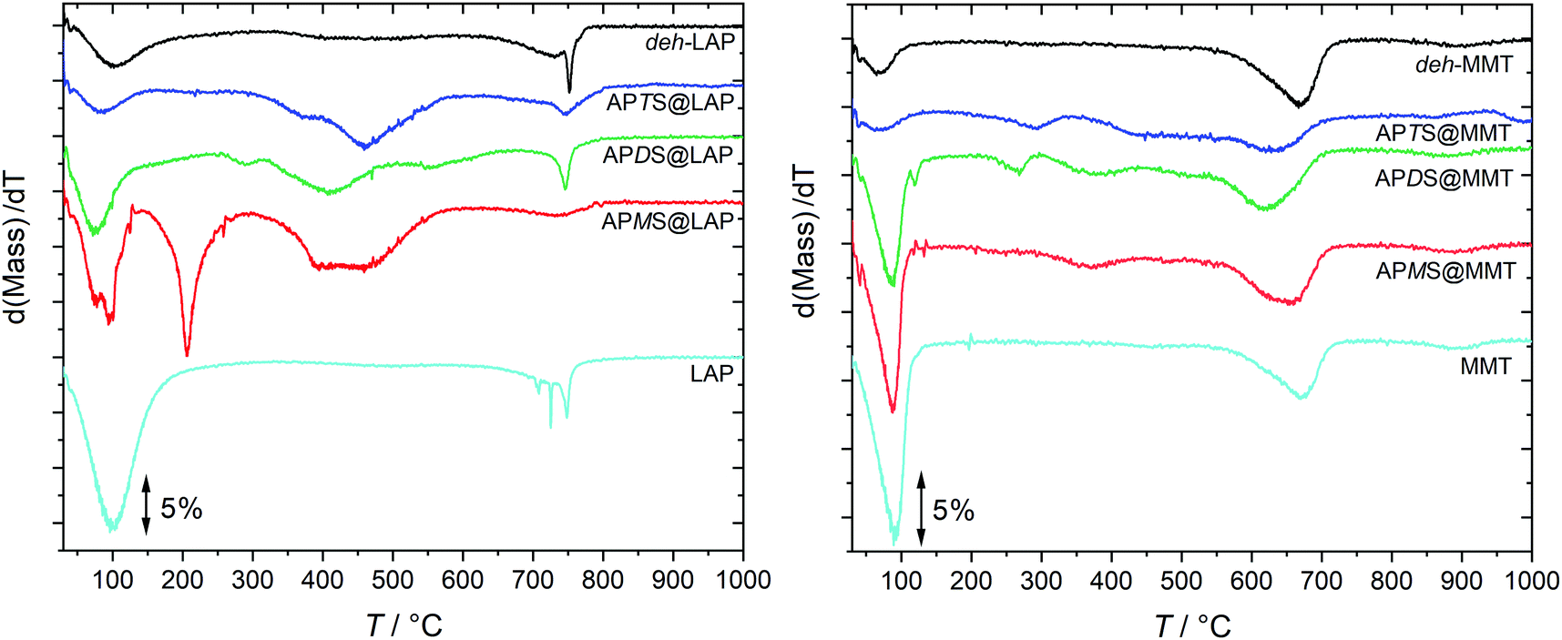 | ||
| Fig. 2 Vertically shifted dTGA traces of the clay-silane hybrids, the pristine clays and the deh-clays. The TGA traces are shown in Fig. S1 (ESI†). | ||
The mass loss in the vicinity of 100 °C was identified to be caused by water which makes up 12 and 6 mass-% in pristine LAP and pristine MMT, respectively. Although the reaction products and the deh-clays were dried at 120 °C, adsorbed humidity during sample storage under ambient conditions probably accounts for that mass loss. This is marginal for the deh-clays and the APTS@clay samples and more pronounced for the APMS@clay and APDS@clay products but still below those observed with the pristine clays. In accordance with XRD and NMR results (cf. Sections 3.2 and 3.4) it is reasonable to assume that this additional water is released from the interlayer spaces of APMS@clay and APDS@clay. Although water from silanol condensation might contribute to the mass loss this scenario is less probable in the light of the higher temperature that was applied during the drying process.
• Silanol grafting to Mg–OH,
• Specific NH2–H2O–NH2 interaction,
• Specific Na+–H2O–NH2 interaction,
• NH2–H2O hidden in silica cavities.
The grafting of the silane's Si–OH on Mg–OH alone would have yielded just one third of the amount of released water (cf. Section 3.1.3.) and FTIR spectroscopy of APMS@LAP shows that the asymmetric stretching of Mg–OH (ν ≈ 650 cm−1) stays intact in the annealed product (Fig. 3).
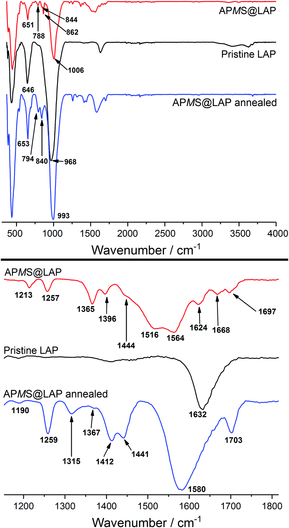 | ||
| Fig. 3 FTIR spectra of APMS@LAP as obtained and annealed at 200 °C in comparison with the pristine clay. The lower part is the zoomed wavenumber range between 1150 and 1800 cm−1. | ||
On the contrary, the last three scenarios are supported by the observation that the APDS@LAP sample releases CO2 around 180 °C which is not detected in APMS@LAP (Fig. S2, ESI†). Carbon dioxide adsorption by APMS will be hampered if its amino group is sterically shielded, e.g., in the hexagonal cavities of the silica layer or chemically tied via hydrogen bonding, either exclusively with water or with the sodium cations involved. In a review Lagaly reported already in 1984 on the intercalation of neutral molecules like amines in smectites. It was suggested that amines coordinate alkali and earth alkali cations through water bridges.42
Interactions between the amino group and water or carbon dioxide in the form of the ammonium salt should have an effect on the N–H vibrations and thus the FTIR spectra of APMS@LAP before and after annealing. Indeed, the patterns in the fingerprint region (700–900 cm−1) and in the range of 1100–1800 cm−1 have been altered by annealing at 200 °C (Fig. 3). Bands at 794, 840, 1190, 1259, 1412, 1441 and 1580 cm−1 for the annealed sample are in excellent accord with the FTIR spectrum reported for dimerized APMS.43 Only the reported band at 1058 cm−1 for the asymmetric stretching of Si–O–Si in the dimer is hidden by the Si–O–Si vibration of the clay in the APMS@LAP hybrid phase (intense band at 993 cm−1).
This suggests that APMS is intercalated as monomer and dimerizes around 200 °C. The relative stability of γ-aminopropylalkoxysilanes in water towards condensation has been attributed to the formation of cyclic structures of the hydrolyzed silane. The silanol is stabilized through intramolecular hydrogen bonding between the Si–OH and the H2N group. An IR absorption at 1510 cm−1 was assigned to the N–H bending vibration within such cycles.43 For the vibrations of the corresponding –NH3+ cation and of the free –NH2 group, lower (1485 cm−1) and higher (1600 cm−1) wavenumbers have been reported, respectively.44,45 The non-annealed sample of APMS@LAP shows bands at 1516 and 1564 cm−1. The former is in good agreement with the presence of cyclic APMS rather than ammonium groups. If we assume that carbon dioxide would be bound as –NH3+ HCO3− ion pairs, the FTIR bands explain that basically no CO2 was detected in the TGA of this hybrid. The other band at 1564 cm−1 exludes the presence of free amino groups.
To summarize, the results show that hydrolyzed APMS is accommodated as intramolecular stabilized cyclic monomer and that N–H interacts with water molecules via hydrogen bonding. At around 200 °C the APMS rings open and two adsorbed H2O molecules per APMS are released according to TGA evaluation (cf. Section 3.1.3). With regard to the silanol a band at 1703 cm−1 of the annealed hybrid can be attributed to free Si–OH groups.46 Nevertheless, another 1/2 equivalent of released H2O per APMS (cf. Section 3.1.3) and a slightly decreased d-value in the annealed sample (cf.Table 1 and Fig. 7d, e) confirm the FTIR results that a distinct fraction of the APMS species should have dimerized.
| Sample | Δmi (%) | ϕ i | Silane per clay site | Reacted Q2 (%) | d-Value (nm) | ζ-Pot. (mV) | |
|---|---|---|---|---|---|---|---|
| x i /(xi + yi) | x i /eqNa | x i /eqedge | |||||
| LAP | — | — | — | — | — | 1.40 | −24 |
| deh-LAP | — | — | — | — | — | 1.28 | n.d. |
| APMS@LAP | 10.2 | 0.418 | 2.1 | 9.0 | 42 | 1.71 | −20 |
| APDS@LAP | 6.9 | 0.322 | 1.4 | 5.9 | 25 | 1.70 | −7 |
| APTS@LAP | 6.8 | 0.328 | 1.4 | 6.1 | 17 | 1.26 | −12 |
| MMT | — | — | — | — | — | 1.16 | −33 |
| deh-MMT | — | — | — | — | — | 1.03 | n.d. |
| APMS@MMT | 2.0 | 0.085 | 0.3 | 12 | u.d. | 1.26 | −29 |
| APDS@MMT | 3.0 | 0.149 | 0.5 | 22 | u.d. | 1.54 | −29 |
| APTS@MMT | 2.6 | 0.145 | 0.5 | 21 | u.d. | 1.12 | −14 |
The mass loss in the intermediate temperature range (300–600 °C) is due to the degradation of the hydrocarbon moieties (propyl, methyl) as well as of the amino groups (vide infra for APMS@LAP). Above 600 °C structural dehydration of the clay takes place.32
A more efficient confinement is imposed by the larger lateral extension of the layers in combination with smaller d-values (Table 1). This broadens the temperature range of the degradation of APMS and APDS which is partially overlapping with the dehydration of the Al-OH sites (cf. Fig. S1 and S3, ESI†). Therefore, the temperature range for the calculation of grafted or intercalated silanes is extended to 800 °C.
The silylation yield can then be calculated from the molar composition of the ashes at 850 °C. These consist of SiO2 from the silane and the oxides from the clay, the latter having a pseudo molecular mass Mj (MLAP = 367, MMMT = 349):
| mash = xi·MSiO2 + yi·Mj. | (1) |
| yi = (mash − Δmi·MSiO2/Mi)/Mj | (2) |
| ϕi = xi/(xi + yi). | (3) |
The calculated silylation yields ϕi (Table 1) may be somewhat underestimated for APMS@LAP and both APTS treated clays due to the unaccomplished constant mass at 850 °C (cf. Section 2.3, Fig. S1, ESI†). Nevertheless, roughly 1/3 of the obtained LAP hybrids consists of the silane, which just makes up approximately 1/8 of the MMT hybrids, with slightly larger and lower values for APMS@LAP and APMS@MMT, respectively. With regard to the amounts of silanes that were recovered in the hybrids after synthesis and centrifugation, yields of 32–50% and 6–11% are calculated for the LAP and for the MMT series, respectively.
In order to show the relation of the fixed silanes to the clays' sites for edge grafting and intercalation, the amounts of silane (xi) are tabulated in proportion to sodium equivalents and edge sites, respectively (Table 1). For the sake of simplicity the latter are estimated assuming disks of 25 nm (LAP) and 250 nm (MMT) diameter with a thickness of 1 nm. This yields a surface fraction for the edges of 0.8 and 8 percent for MMT and LAP, respectively. Although the derived numbers do not reflect the actual proportions of intercalated and edge grafted silanes they provide hypothetic population densities for exclusive intercalation or edge grafting, respectively.
Hence, for intercalated APMS in LAP the value close to two is plausibly large to explain the proposed Na+–H2O–NH2 compartments which retain water at temperatures up to 200 °C (cf. Section 3.1.1.) and allow for enhanced Na+ dynamics (cf. Section 3.4). On the other hand, values substantially below one for intercalated silanes in MMT underline the reluctance of the host to accommodate the guest species which will be discussed in Section 3.6.
3.2 Altered basal distances
Silane intercalation should lead to a widening of the interlayer space. Therefore X-ray diffraction (XRD) measurements were carried out and the low angle sections which comprise the (00![[small script l]](https://www.rsc.org/images/entities/char_e146.gif) ) reflections of the layer stacking are shown in (Fig. 4). The corresponding d-values are given in Table 1. A moderate (MMT) to poor (LAP) stacking order of the pristine as well as of the treated clays is causing broad humps rather than peaks. Nevertheless, it is obvious that toluene leads to dehydration and shrinkage of the interlayer space according to the maxima of the (001) humps which are shifted to higher 2θ values for deh-LAP and deh-MMT. The corresponding d-values of 1.28 nm for deh-LAP and 1.03 nm for deh-MMT are those reported for a mono-hydrated and a dehydrated state, respectively.47 This is in accordance with the higher water content of pristine LAP as observed with TGA (cf.Fig. 2 and Fig. S1, ESI†). For the modified clays, silylation with APMS and APDS leads to an increase of the d-value of both clays as the maxima are shifted to smaller 2θ values. For MMT the widening is more pronounced with APDS@MMT, whereas both silanes basically yield the same basal distance in the LAP based hybrids. Apparently, no change for d001 can be recognized for the APTS treated clays. However, a barely recognizable, broad hump found for APTS@MMT around 2θ = 5° might be interpreted as an expanded peripheral zone caused by edge grafting of APTS.48
) reflections of the layer stacking are shown in (Fig. 4). The corresponding d-values are given in Table 1. A moderate (MMT) to poor (LAP) stacking order of the pristine as well as of the treated clays is causing broad humps rather than peaks. Nevertheless, it is obvious that toluene leads to dehydration and shrinkage of the interlayer space according to the maxima of the (001) humps which are shifted to higher 2θ values for deh-LAP and deh-MMT. The corresponding d-values of 1.28 nm for deh-LAP and 1.03 nm for deh-MMT are those reported for a mono-hydrated and a dehydrated state, respectively.47 This is in accordance with the higher water content of pristine LAP as observed with TGA (cf.Fig. 2 and Fig. S1, ESI†). For the modified clays, silylation with APMS and APDS leads to an increase of the d-value of both clays as the maxima are shifted to smaller 2θ values. For MMT the widening is more pronounced with APDS@MMT, whereas both silanes basically yield the same basal distance in the LAP based hybrids. Apparently, no change for d001 can be recognized for the APTS treated clays. However, a barely recognizable, broad hump found for APTS@MMT around 2θ = 5° might be interpreted as an expanded peripheral zone caused by edge grafting of APTS.48
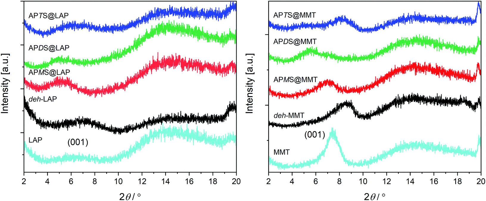 | ||
| Fig. 4 Small angle XRD sections of the LAP and of the MMT series. The positions of the 001 peaks of the pristine clays are indicated. | ||
To summarize, the XRD results exclude noteworthy intercalation in case of APTS whereas they confirm the accommodation of APMS and APDS.
3.3 Altered silica sites (29Si NMR)
The reaction of the silanes with Si–OH groups from silica tetrahedra along the rims of the sheets can be monitored with 29Si solid-state NMR measurements. The spectra obtained with the six silylated samples are presented in Fig. 5.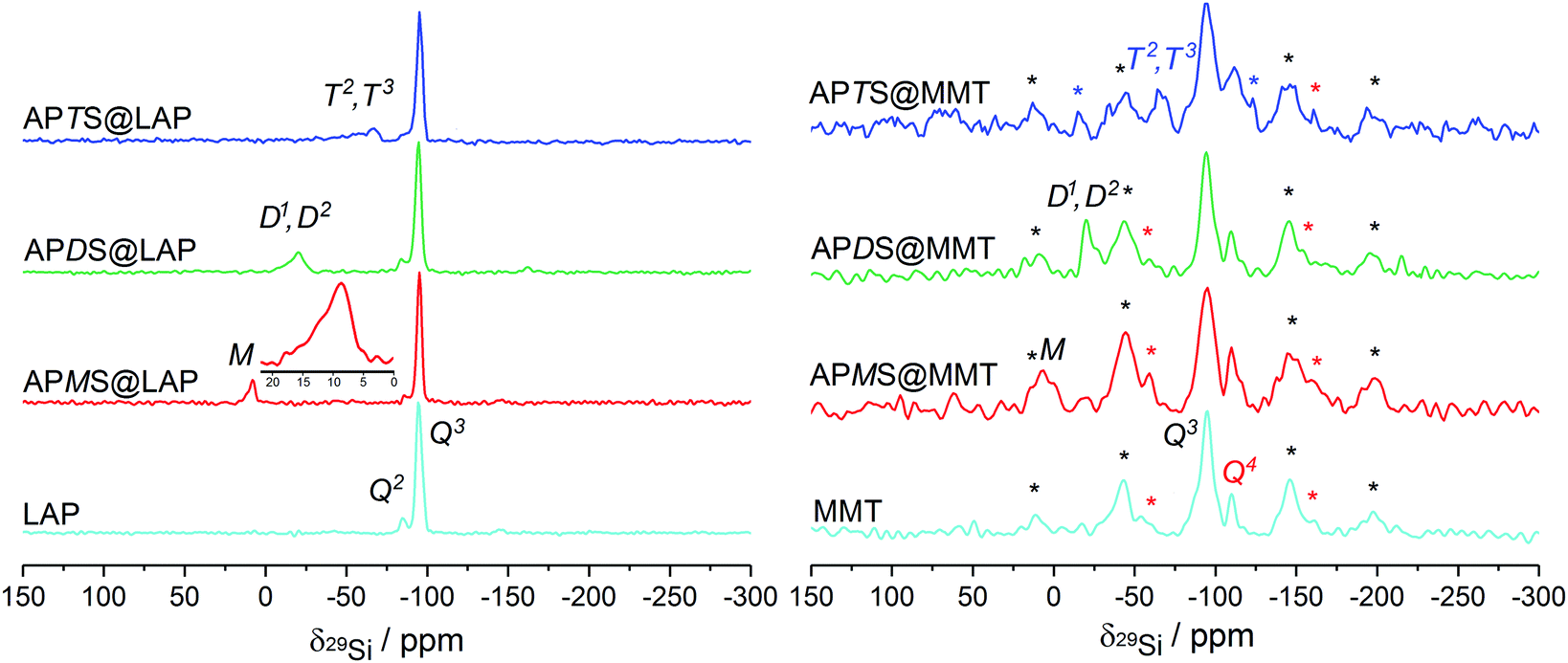 | ||
| Fig. 5 Proton-decoupled 29Si NMR spectra of the LAP and MMT series, obtained under MAS at 3 kHz. Red, black and blue asterisks denote spinning-sidebands of the Q3, Q4 and T2/T3 site, respectively. | ||
Although absolute intensities are inaccessible because of long spin–lattice relaxation times for Q3 sites, a Q2/Q3 ratio of 0.12 from peak deconvolution is in a good agreement with previous results.51
Treatment with APMS reduces the Q2/Q3 ratio from 0.12 to 0.07 which indicates that about 42% of the Si–OH groups have reacted. A broad, asymmetric M signal for R3SiO around 10 ppm can be assigned to grafted or dimerized APMS (M1 peak at 8.6 ppm)51 as well as the silanol (M0 peak at 12 ppm). However, the latter is not resolved but clearly visible as a distinct shoulder (cf.Fig. 5, inset). The M0 peak for the pristine alkoxy group in APMS has been reported to be at 16.9 ppm.52
In APDS@LAP a Q2/Q3 intensity ratio of 0.09 means that 25% of the silanols have been consumed in accordance with a broad and unresolved signal at −20.3 ppm. This is attributed to D2 species (R2SiO2) of oligomerized APDS. The shoulder at −17 ppm can be assigned to minor contents of D1 species (R2Si(OEt)O).53,54
With APTS, the Q2/Q3 ratio increases to 0.1 which corresponds to 17% of silanol conversion. This yields two broad peaks at −57.6 ppm and −66.6 ppm that are caused by T2 (RSi(OEt)O2) and T3 (RSiO3) silicon sites, respectively, being part of branched APTS oligomers.32,51,54,55
To summarize, the decrease of the Q2 signal intensity provides evidence of edge-grafting which decreases in the order APMS@LAP > APDS@LAP > APTS@LAP whereas the appearance of M, D and T peaks proves the condensation of the silanes' silanol groups.
After the reaction with either of the silanes, the Q2 shoulder is no longer recognizable because of the increased width of the Q3 peak. However, the appearance of M, D1/D2 and T2/T3 peaks at 6.9 ppm, −19.9 ppm and −67.9 ppm prove similar reaction pathways of the silanes as described in the previous section.51,53–55
3.4 Solvated sodium cations (23Na NMR)
The intercalation of silanes and their subsequent hydrolysis and condensation in the confined interlayer space is expected to change the state of the sodium cations, in particular their solvation sphere. This should have an impact on the electric field gradient and thus influence the anisotropy of the field gradient tensor of the sodium cations, which can be monitored by solid state 23Na NMR. A down-field shift of the 23Na peak in combination with a line narrowing has been attributed to an increased hydration of Na+ in the clays' interlayer space.57–59 Typically, signals in the vicinity of −14 ppm have been reported for sodium clays like MMT.57 The 23Na NMR spectra of the silylated and the reference clays are shown in Fig. 6.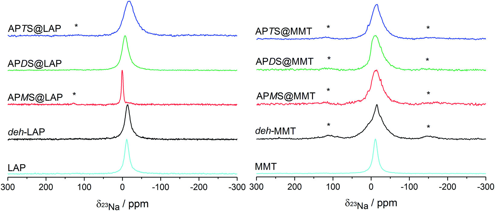 | ||
| Fig. 6 Proton-decoupled 23Na NMR spectra of the LAP and MMT series, obtained under MAS at 10 kHz. Spinning sidebands are labelled with asterisks. | ||
For the silylated samples the peak width significantly narrows from APTS to APMS. This reveals a detachment of planar coordinated Na+ ions near the clay surface (large quadrupole coupling) to a more central position and sphere-like coordination. The latter will enhance the Na+ dynamics which also narrows the lines.
The down-field shift, 0.5 ppm for APMS and −6.3 ppm for APDS, reflects changes in the electric field gradient of the Na+ ions in the neighborhood of the intercalated silanes. In particular the distinctly narrow and down-field shifted peak of APMS supports the findings obtained from the unique thermal behaviour of this hybrid material (cf. Section 3.1.1): the high water content and therefore a more symmetrical coordination sphere. On the contrary, the distinctly up-field shifted peak of APTS is in line with the absence of silane intercalation.
However, the lineshapes of all treated MMT samples indicate three nonequivalent sites as suggested by deconvolution.58 It can be concluded that sodium cations are present in different surroundings in the vicinity of the clay surface. In accordance with rather low silylation yields and modest increases of the interlayer distances (Table 1) the small observed changes may even not be attributed to the presence of intercalated silane. Only the distinct tailing on the up-field side and the steep slope on the down-field side of the peak of APDS@MMT may feature some solvation effect induced by the guest species. This sample is also the one with the largest d-value in the MMT series.
3.5 Further probes
In addition, 7Li and 27Al MAS NMR measurements were carried out for LAP- and MMT-based samples, respectively (cf. Fig. S6 and S7, ESI†). However, the spectra of the pristine and of the silylated clays are too similar for both nuclei in order to extract suitable information about the silylation impact. Basically, the 27Al spectra of MMT show broad signals of four- and six-fold coordinated aluminum.60Finally, further probes have been considered to support the results and are discussed briefly in the ESI.† Whereas EDX fails to unambiguously identify and locate the silanes at and within the clay lattice, respectively, zeta-potential measurements are expected to reveal the presence of positive charges that would result from protonated amino groups which are covalently attached to the particles through silylation. These were measured directly after dispersion of the clays in water (Table 1, cf. ESI,† for more details). They show that the silylation partly compensates the negative charge of the pristine particles. This effect is more pronounced for the LAP samples, which reflects the higher proportion of edges due to the smaller aspect ratio. With regard to the silanes, the shifted charge is most distinct for APTS, which does not intercalate and selectively binds to the layers' rims.
3.6 Silylation modes
Based on the analytical results various scenarios for the silane-clay hybrid formation with respect to chemical grafting and host–guest interaction are discussed regarding the role of the silanes' substitution pattern and the clays' peculiarities.APTS. Overall, the combined TGA, XRD and solid state NMR results prove that APTS, contrary to APMS and APDS, reacts exclusively with the rims of both clays. This is in accordance with previously reported results on the silylation of LAP with another trialkoxy silane32 but contrasts the findings of several other studies in which elevated temperatures were applied.34,61,62 However, Borrego et al.34 showed an XRD curve for their APTS@MMT analogue, which resembles the one of this work. The barely recognizable, broad hump around 2θ = 5° of low intensity was attributed by Asgari et al. to a widened and distorted rim of the layers.48
Our findings can best be understood to reflect branched APTS oligomers. They only consume a fraction of Si–OH at the edges due to steric constraints and low residual numbers of silanol groups (Fig. 7c). Oligomerization results from the high probability of condensation reactions between hydrolyzed silanes due to the high number of ethoxy groups in APTS. Grafted oligomers seal the layers' rims and thus impede further intercalation of APTS and its derivatives (Fig. 7c left edge). Nevertheless, in an early stage of MMT silylation, species might have successfully penetrated the interlayer space and formed a peripheral zone with an increased d-value. Even for the lower d-value the distance between neighboring silica sites is too wide to be linked through monomeric APTS (Fig. 7c right edge).
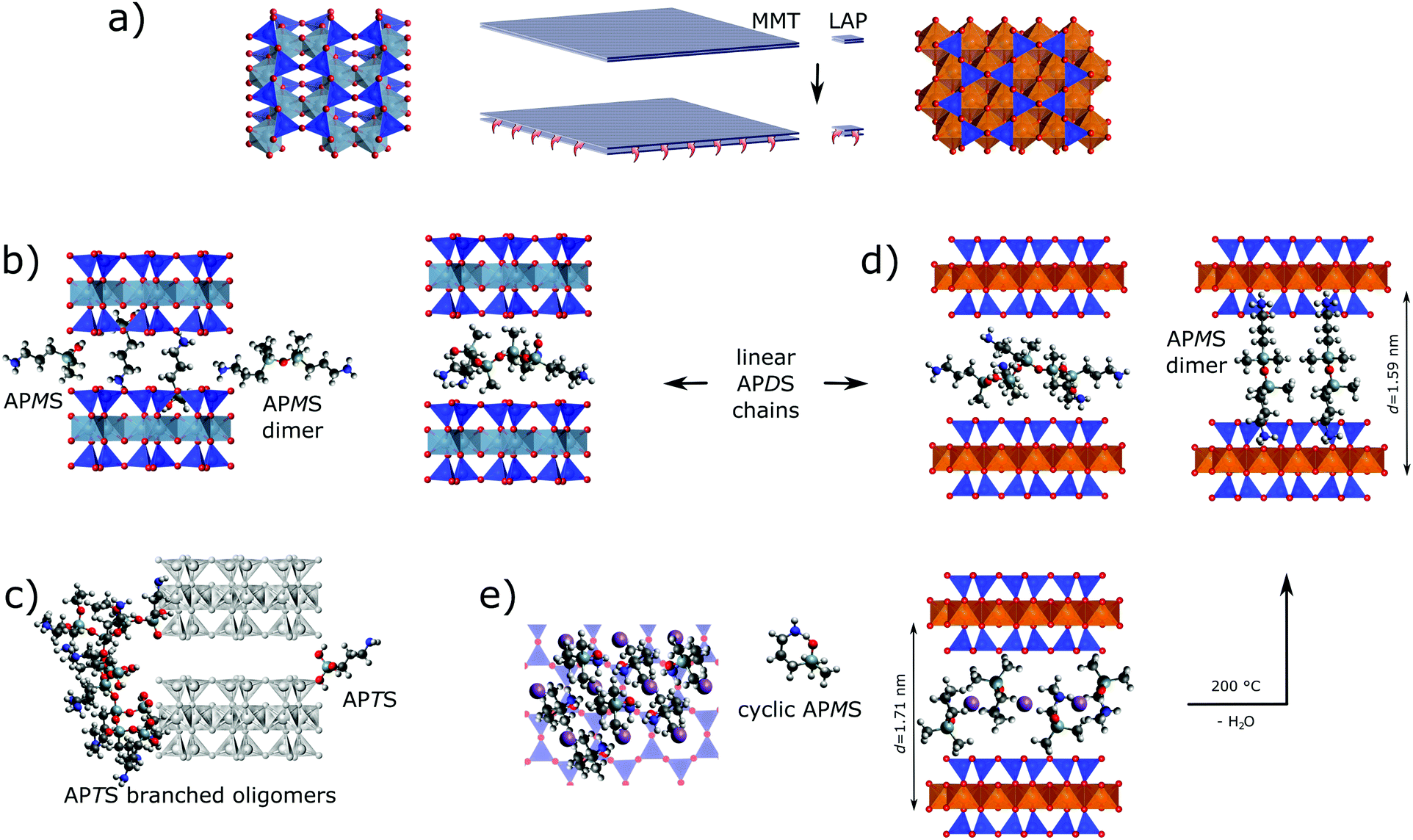 | ||
| Fig. 7 Intercalation of APMS and APDS versus edge grafting. (a) Size comparison and top views of clay layer sections (left MMT, right LAP). (b) No clear preference for the intercalation mode of APMS in APMS@MMT can be deduced from the basal distance if silica cavities accommodate amino or methyl groups, whereas APDS oligomers may fit the interlayer space of APDS@MMT without filling of the silica cavities. (c) Edge grafting of branched APTS oligomer versus monomeric APTS on either clay (d-value of APTS@MMT is shown). (d) Linear APDS oligomers fill the interlayer space of LAP in a similar way as in MMT, whereas fully extended, dimerized APMS (formed at 200 °C) only fits the interlayer space in an almost normal orientation if both amino groups are accommodated by opposing silica cavities. (e) Tentative intercalation scenario of APMS@LAP with cyclic APMS monomers in normal orientation. Projection along the clay stacking (left) visualizes lateral space filling whereas the cross-sectional view (right) reveals how Na+ (purple spheres) in a central plane can be surrounded by NH2/NH3+ groups (2 H2O per NH2 not shown). Drawn true to scale. | ||
APMS and APDS. To the best of our knowledge, silylation of LAP and MMT with APMS and APDS in a non-polar solvent like toluene has not yet been reported. Our results provide evidence for the intercalation of both homologous silanes into both clays. This contradicts reported results for the silylation of LAP with mono alkoxy-silanes that are bearing an octyl or a methacryloxypropyl group, respectively.32,33 In both cases the authors did not observe an increase of the interlayer space. Therefore it is reasonable to assume that the polarity of the primary amino group enables intercalation.
As already argued for the grafting of APTS quick hydrolysis will also take place with APMS and APDS. However, with fewer alkoxy groups the probability of edge grafting increases while grafted species are less (APDS) or not (APMS) bulky. Hence, more species can freely enter the interlayer space. Contrary to APDS silanols which yield linear chains, APMS silanols just condense to dimers. Nevertheless, γ-aminopropyl alkoxysilanes are known to be relatively stable even in aqueous phase which was explained by intramolecular H-bonding between NH2 and Si–OH.43 Consequently, in case of APMS with a single silanol group, intercalation of monomeric rings becomes more probable.
From a mechanistic and chemical perspective, a larger interlayer space, a smaller aspect ratio and a higher water content (that is linked with the pristine inter-layer distance) facilitate intercalation as observed with LAP. Additionally, different acidities of the metal hydroxide groups will yield different amine/ammonium equilibria of the silanes. Given a more acidic Al–OH and thus the presence of ammonium cations electrostatic repulsion between them and sodium as well as electrostatic attraction between ammonium and immobile counter ions (Al–O−) would also explain lower silylation yields with MMT and smaller interlayer distances. Within APMS@MMT, homogeneously oriented APMS monomer fits the interlayer distance, wheres a normal (or tilted) orientation would need the hexagonal silica cavities for the accommodation of either amino or methyl groups. The latter also applies for dimerized APMS (Fig. 7b).
This contrasts APMS@LAP which combines the highest silylation yield with the largest d-value, a rather thermostable water reservoir and distinct sodium dynamics. In accordance with the less acidic nature of Mg–OH intramolecular hydrogen bonding of the silanol with the γ-amino group can prevail and monomeric APMS is accommodated as rings in a normal or tilted orientation (Fig. 7e).
Although the precise assembly of silane, water and sodium evades the probes used in this study, sodium cations could thus be encircled in a central plane by water and polar NH2 (or NH2–H–OSi) moieties of silanes. The trimethylene sides of the APMS rings and their geminal methyl groups may then form hydrophobic arrays throughout the interlayer space. In contrast to more open and less ordered arrangements of linear APDS oligomers, such a compartmentalization of water withstands the drying process of the product but collapses at higher temperature: APMS rings open and 2.5 H2O per guest molecule are leaving the interlayer spaces. Bands in the FTIR spectrum, the half equivalent water per silane and a slightly shrunk d-value (Δd = 0.12 nm, cf. Fig. S4, ESI†) suggest the presence of dimerized APMS besides residual, monomeric silanol after annealing.
The drawn picture is probably oversimplified. It is well known that LAP is chemically not inert in aqueous phase63 and that it actually is a composite mineral from hectorite with ≈25% kerolite.64 Regarding MMT the situation is more complex because of a heterogeneous layer charge density in MMT. A kind of staging effect was proven by Stul and Mortier65 by means of “apparent d-values” for a homologous series of alkyl ammonium ions and a lateral uneven Fe(II) distribution was unveiled by Morris et al. with 27Al NMR spectroscopy.60 Such patchiness of charge (and Na+) density will have an impact on the uptake and accommodation of APDS and APMS.
4 Conclusion
To the best of our knowledge the silylation in a non-polar solvent of LAPONITE® and montmorillonite with three γ-aminopropyl(methyl,ethoxy)silanes of a homologous series with regard to the number of methyl and ethoxy groups is reported for the first time. This systematic investigation, which comprises the dehydrated clays as reference materials, unambiguously reveals the interplay between the silanes' reaction pathways and the clays' aspect ratio, water content and the acidity of the metal hydroxide group.Contrary to previous findings with other mono-alkoxy silanes γ-aminopropyl bearing silanes with one and two alkoxy groups can be intercalated due to the polarity and the hydrogen accepting role of the amino group. Remarkably, the uptake of mono-alkoxy silane in cyclic form leads to compartmentalization between polar domains of water, sodium and amino groups through hydrophobic walls that are formed by the methyl and trimethylene moieties.
The thermal stability of such arrangements may be used in applications where water is supposed to play a destructive role. This can be hydrolysis in interfaces between unlike materials, e.g., macroscopic parts from metal and polymer or nano-composites. With increasing demands for circular economies for the sake of sustainable growth it is highly desirable to separate the metal or the inorganic filler from the polymer phase once the service life has ended. Consequently, local release of water may initiate and facilitate the separation process via hydrolytic scission of covalent or hydrogen bonds in the interface or within polymer chains, respectively. Beyond that, blasting of the stacked clay layers would further promote the intended degradation of a composite. In this respect this study may spur the design of similar assemblies, in particular using clays which combine basicity and a much larger aspect ratio. In conjunction with higher heating rates the latter should limit diffusive water loss in favour of expansion and interphase burst.
In order to achieve promising architectures further insights into the space-time dependent chemistry and intercalation process could be obtained via real time monitoring of the clay's d-value during the silylation process using small angle scattering.
Finally, our results may be helpful for a (re)interpretation of previously published, apparently contradictory findings on the silylation of smectites, since a homologous series was used under identical reaction conditions.
Author contributions
W. K.: Analyses, evaluation of results. K. Z.: Silylation reactions, analyses. A. O.: Analyses, evaluation of results. W. B. & C. S.: Initiation, concept. H. H.-B: Concept, methodology, evaluation, review. All authors contributed to the manuscript.Conflicts of interest
There are no conflicts to declare.Acknowledgements
The help of Nadine Buitkamp (EDX and focussed ion beam experiments), Christian Weinberger (BET and XRD), and Josefin Klippstein (TGA-mass spectrometry) is gratefully acknowledged.Notes and references
- A. Okada, Y. Fukushima, M. Kawasumi, S. Inagaki, A. Usuki, S. Sugiyama, T. Kurauchi and O. Kamigaito, Composite material and process for manufacturing same, 1986, US patent 4739007 Search PubMed.
- Y. Kojima, A. Usuki, M. Kawasumi, A. Okada, T. Kurauchi and O. Kamigaito, J. Polym. Sci., Part A: Polym. Chem., 1993, 31, 983–986 CrossRef CAS.
- D. C. Lee and L. W. Jang, J. Appl. Polym. Sci., 1996, 61, 1117–1122 CrossRef CAS.
- A. Usuki, Y. Kojima, M. Kawasumi, A. Okada and Y. Fukushima, J. Polym. Sci., Part A: Polym. Chem., 1993, 8, 1179–1184 CAS.
- T. Lan, P. D. Kaviratna and T. J. Pinnavaia, Chem. Mater., 1994, 6, 573–575 CrossRef CAS.
- A. Usuki, A. Tukigase and M. Kato, Polymer, 2002, 43, 2185–2189 CrossRef CAS.
- Y. Kojima, A. Usuki, M. Kawasumi, A. Okada, Y. Fukushima, T. Kurauchi and O. Kamigaito, J. Mater. Res., 1993, 8, 1185–1189 CrossRef CAS.
- H. M. Park, X. Li, C. Z. Jin, C. Y. Park, W. J. Cho and C. S. Ha, Macromol. Mater. Eng., 2002, 287, 553–558 CrossRef CAS.
- A. Meunier, Clays, Springer-Verlag, Berlin, 2005 Search PubMed.
- Y.-M. Chen, H.-C. Lin, R.-S. Hsu, B.-Z. Hsieh, Y.-A. Su, Y.-J. Sheng and J.-J. Lin, Chem. Mater., 2009, 21, 4071–4079 CrossRef CAS.
- D. W. Thompson and J. T. Butterworth, J. Colloid Interface Sci., 1992, 151, 236–243 CrossRef CAS.
- L. Ammann, F. Bergaya and G. Lagaly, Clay Miner., 2005, 40, 441–453 CrossRef CAS.
- L. Delavernhe, M. Pilavtepe and K. Emmerich, Appl. Clay Sci., 2018, 151, 175–180 CrossRef CAS.
- A. Okada and A. Usuki, Mater. Sci. Eng., C, 1995, 3, 109–115 CrossRef.
- E. P. Giannelis, Adv. Mater., 1996, 8, 29–35 CrossRef CAS.
- C.-M. Leu, Z.-W. Wu and K.-H. Wei, Chem. Mater., 2002, 14, 3016–3021 CrossRef CAS.
- J. W. Gilman, C. L. Jackson, A. B. Morgan, R. Harris, E. Manias, E. P. Giannelis, M. Wuthenow, D. Hilton and S. H. Phillips, Chem. Mater., 2000, 12, 1866–1873 CrossRef CAS.
- I. K. Tonle, E. Ngameni and A. Walcarius, Electrochim. Acta, 2004, 49, 3435–3443 CrossRef CAS.
- B. Arkles, CHEMTECH, 1977, 7, 766 CAS.
- E. P. Plueddemann, Silane coupling agents, Springer, US, 1991 Search PubMed.
- D. Briesenick and W. Bremser, Prog. Org. Coat., 2015, 82, 26–32 CrossRef CAS.
- J.-T. Kim, D.-Y. Lee, T.-S. Oh and D.-H. Lee, J. Appl. Polym. Sci., 2003, 89, 2633–2640 CrossRef CAS.
- I. K. Tonle, E. Ngameni, D. Njopwouo, C. Carteret and A. Walcarius, Phys. Chem. Chem. Phys., 2003, 5, 4951–4961 RSC.
- S. R. Wasserman, L. Soderholm and U. Staub, Chem. Mater., 1998, 10, 559–566 CrossRef CAS.
- A. B. Bourlinos, D. D. Jiang and E. P. Giannelis, Chem. Mater., 2004, 16, 2404–2410 CrossRef CAS.
- K. Song and G. Sandi, Clays Clay Miner., 2001, 49, 119–125 CrossRef CAS.
- F. Piscitelli, P. Posocco, R. Toth, M. Fermeglia, S. Pricl, G. Mensitieri and M. Lavorgna, J. Colloid Interface Sci., 2010, 351, 108–115 CrossRef CAS PubMed.
- N. N. Herrera, J.-M. Letoffe, J.-P. Reymond and E. Bourgeat-Lami, J. Mater. Chem., 2005, 15, 863–871 RSC.
- H. He, J. Duchet, J. Galy and J. F. Gerard, J. Colloid Interface Sci., 2005, 288, 171–176 CrossRef CAS PubMed.
- W. Shen, H. P. He, J. Zhu, P. Yuan and R. L. Frost, J. Colloid Interface Sci., 2007, 313, 268–273 CrossRef CAS PubMed.
- J. Zhu, H. He, J. Guo, D. Yang and X. Xie, Chin. Sci. Bull., 2003, 48, 368–372 CAS.
- N. N. Herrera, J. M. Letoffe, J. L. Putaux, L. David and E. Bourgeat-Lami, Langmuir, 2004, 20, 1564–1571 CrossRef CAS.
- L. M. Daniel, R. L. Frost and H. Y. Zhu, J. Colloid Interface Sci., 2008, 321, 302–309 CrossRef CAS PubMed.
- T. Borrego, M. Andrade, M. L. Pinto, A. R. Silva, A. P. Carvalho, J. Rocha, C. Freire and J. Pires, J. Colloid Interface Sci., 2010, 344, 603–610 CrossRef CAS PubMed.
- L. Su, Q. Tao, H. He, J. Zhu, P. Yuan and R. Zhu, J. Colloid Interface Sci., 2013, 391, 16–20 CrossRef CAS PubMed.
- J. Herzfeld and A. E. Berger, J. Chem. Phys., 1980, 73, 6021–6030 CrossRef CAS.
- K. Eichele, HBA 1.7.5: Herzfeld-Berger analysis program, 2015, http://anorganik.uni-tuebingen.de/klaus/soft/.
- W. Oueslati, M. Ammar and N. Chorfi, Minerals, 2015, 5, 507–526 CrossRef CAS.
- W. Oueslati and M. Meftah, Adv. Mater. Sci. Eng., 2018, 2018, 5219624 Search PubMed.
- A. Viani, A. F. Gualtieri and G. Artioli, Am. Mineral., 2002, 87, 966–975 CrossRef CAS.
- D. Senich, T. Demirel and R. Handy, Proc. Natl. Acad. Sci. U. S. A., 1966, 73, 212–218 CAS.
- G. Lagaly, Philos. Trans. R. Soc., A, 1984, 311, 315–332 CrossRef CAS.
- H. Ishida, C.-H. Chiang and J. L. Koenig, Polymer, 1982, 23, 251–257 CrossRef CAS.
- C.-H. Chiang, H. Ishida and J. L. Koenig, J. Colloid Interface Sci., 1980, 74, 396–404 CrossRef CAS.
- S. Culler, H. Ishida and J. Koenig, J. Colloid Interface Sci., 1985, 106, 334–346 CrossRef CAS.
- D.-Q. Yang, M. Meunier and E. Sacher, Appl. Surf. Sci., 2005, 252, 1197–1201 CrossRef CAS.
- E. Ferrage, Clays Clay Miner., 2016, 64, 346–371 CrossRef.
- M. Asgari and U. Sundararaj, Appl. Clay Sci., 2018, 153, 228–238 CrossRef CAS.
- A. P. S. Mandair, P. J. Michael and W. R. McWhinnie, Polyhedron, 1990, 9, 517–525 CrossRef CAS.
- L. Delevoye, J. L. Robert and J. Grandjean, Clay Miner., 2003, 38, 63–69 CrossRef CAS.
- P. A. Wheeler, J. Wang, J. Baker and L. J. Mathias, Chem. Mater., 2005, 17, 3012–3018 CrossRef CAS.
- T.-M. Lee, C.-W. Ma, C.-C. M. Hsu and H.-L. Wu, J. Appl. Polym. Sci., 2006, 3491-3499, 1197–1201 Search PubMed.
- C. Ivaldi, I. Miletto, G. Paul, G. B. Giovenzana, A. Fraccarollo, M. Cossi, L. Marchese and E. Gianotti, Molecules, 2019, 24, 1–15 CrossRef PubMed.
- S. K. Young, W. L. Jarrett and K. A. Mauritz, Polymer, 2002, 43, 2311–2320 CrossRef CAS.
- M. Oubaha, M. Dubois, P. Murphy and B. Etienne, J. Sol-Gel Sci. Technol., 2006, 38, 111–119 CrossRef CAS.
- C. H. Rhee, H. K. Kim, H. Chang and J. S. Lee, Chem. Mater., 2005, 17, 1691–1697 CrossRef CAS.
- T. Ohkubo, K. Saito, K. Kanehashi and Y. Ikeda, Sci. Technol. Adv. Mater., 2004, 5, 693–696 CrossRef CAS.
- K. Sato, K. Numata, W. Dai and M. Hunger, Appl. Phys. Lett., 2014, 104, 131901 CrossRef.
- V. Laperche, J. Lambert, R. Prost and J. Fripiat, J. Phys. Chem., 1990, 94, 8821–8831 CrossRef CAS.
- H. D. Morris, S. Bank and P. D. Ellis, J. Phys. Chem., 1990, 94, 3121–3129 CrossRef CAS.
- L. C. Bandeira, P. S. Calefi, K. J. Ciuffi, E. H. de Faria, E. J. Nassar, M. A. Vicente and R. Trujillano, Polim. Int., 2012, 61, 1170–1176 CrossRef CAS.
- C. Pereira, S. Patrício, A. R. Silva, A. L. Magalhães, A. P. Carvalho, J. Pires and C. Freire, J. Colloid Interface Sci., 2007, 316, 570–579 CrossRef CAS PubMed.
- S. Jatav and Y. M. Joshi, Appl. Clay Sci., 2014, 97-98, 72–77 CrossRef CAS.
- G. E. Christidis, C. Aldana, G. D. Chryssikos, V. Gionis, H. Kalo, M. Stöter, J. Breu and J.-L. Robert, Minerals, 2018, 8, 314 CrossRef.
- M. S. Stul and W. J. Mortier, Clays Clay Miner., 1974, 22, 391–396 CrossRef CAS.
Footnote |
| † Electronic supplementary information (ESI) available: TGA-MS, XRD, EDX, 29Si NMR Herzfeld–Berger analysis, 23Na NMR, 7Li NMR, 27Al NMR, ζ-potential, BET surface, SEM. See DOI: 10.1039/d1cp03321b |
| This journal is © the Owner Societies 2022 |