 Open Access Article
Creative Commons Attribution 3.0 Unported Licence
Predicting a process window for the roll-to-roll deposition of solvent-engineered SnO2 in perovskite solar cells†
David
Richards
,
Daniel
Burkitt
 ,
Rahul
Patidar
 ,
David
Beynon
and
Trystan
Watson
 *
*
SPECIFIC, Faculty of Science and Engineering, Swansea University, Swansea, Wales. E-mail: t.m.watson@swansea.ac.uk
First published on 23rd September 2022
Abstract
Lightweight flexible perovskite solar cells (PSCs) offer advantages over rigid solar cells including power to weight, variety of form factor and ability to scale. With breakthroughs in the power conversion efficiency (PCE) of PSCs, scaling up PSCs with similar performance has become a topic of interest. Roll-to-roll (R2R) manufacturing is one promising method to leverage the low temperature processing ability of PSCs. In this work, we demonstrate the R2R slot-die coating of the SnO2 electron transport layer, applying the low flow limit to showcase its pertinence in assessing the coating window for slot-die coating. It was observed that low flow limit can accurately predict the processing window for solvent-engineered SnO2 solutions streamlining scale up from benchtop to full R2R coating. We achieved a PCE of 16.35% for R2R-coated SnO2-based MAPbI3 perovskite devices exceeding the performance of benchtop-coated devices.
1 Introduction
With the rise in the power conversion efficiency (PCE) of perovskite solar cells (PSCs) in the last decade, interest is now growing in technologies that facilitate the transition of lab scale processes to industrial scale. Due to their high defect tolerance, solution processed PSCs are an ideal candidate for high volume manufacture.1 At present, spin coating is the laboratory default method for depositing layers that demonstrate high efficiency but the method is incompatible with industrial scale as it suffers from low throughput and high material wastage. The future of perovskite solar cells lies in overcoming these disadvantages whilst maintaining high PCE and this can be achieved by the fabrication of PSCs at low temperature using high volume manufacturing techniques such as roll-to-roll (R2R) where the material is passed continuously between rollers underneath a print head. Under these circumstances, scalable printing methods such as screen printing, gravure printing, blade coating, inkjet printing, spray coating and slot-die coating can be applied. Most of these techniques are well studied albeit only in sheet-to-sheet (S2S) manufacturing,2–6 where the sample is passed from one coating station to the other. Although this represents a sensible development pathway, it is still a step removed from industrial scale and loses many of the unique benefits of perovskites such as the ability to deposit and anneal in very short time-scales.7,8 Further advantages include the ability to pre-meter materials, efficient use of materials and the ability to process a wide range of ink rheologies. Slot-die coating applied via R2R is the most common printing technique for manufacturing in both PSCs and organic photovoltaics (OPVs).9–14Developments so far in the R2R manufacturing of PSCs utilize flexible plastic substrates, typically polyethylene terephthalate (PET). Since PET cannot be used at high temperature (>150 °C), all the layers printed on PET must be processed under this temperature limit. This limits the choice of the electron transport layer (ETL) and hole transport layer (HTL), which make up critical components of the device stack either side of the photoactive perovskite layer. Commonly used high efficiency transport layers such as titanium dioxide (TiO2) and nickel oxide (NiO2) require high temperature sintering (>400 °C) to achieve efficient, compact pin hole free layers. Tin oxide (SnO2), however, is a potential low-cost, stable ETL capable of high efficiency, and most importantly, can be processed at low temperatures for deposition on flexible, temperature sensitive substrates;15–17 the feasibility of the R2R slot-die coating was demonstrated by Galagan et al.;10 however, this formed part of a larger body of work and was not discussed in detail despite the fundamental importance of successful device construction.
This work focuses exclusively on the challenges and complexity of the SnO2 layer, which plays a fundamental role in the delivery of a fully printable R2R perovskite solar cell. A full scale up route is presented from spin coating through benchtop slot-die to full roll-to-roll coating. Determination of the optimal ETL structure is achieved through spin coating. Solvent engineering is then employed to enable the transfer to S2S slot-die coating where the processing window for the different formulations is characterized using the low flow limit. The low flow limit model18 is used to define the coating window, which represents a region of acceptable coating quality in the space of deposition parameters; the results are employed in the final R2R stage to avoid expensive and iterative experimentation in transferring successful lab-scale spin-coated SnO2 films using industry-scaled R2R methods on coated flexible PET/ITO substrates.
2 Experimental methods
Spin-coated control devices were fabricated on 15 Ohm sq−1 ITO-coated glass substrates, which were cleaned sequentially using dilute Hellmanex, water, acetone and 2-propanol. Sheet-to-sheet and roll-to-roll devices were manufactured on 50 Ohm sq−1 ITO-coated PET (Meko-print) with no pre-cleaning routine. Sheet-to-sheet coatings were made using a bench-top slot-die coater (FOM), with an inline forced convection oven, contained in a fume-hood within a clean room environment with controlled humidity of 30% RH, matching the environmental conditions required for consistent perovskite coating ensuring compatibility with a continuous sequential coating process. The slot-die coating head had a coating width of up to 100 mm, and patterned shims were used to define coated areas, with the corresponding meniscus guides being used to aid meniscus formation between the slot-die head lips and the substrate. The length of the meniscus guide protrusions was 1000 μm. The slot-die head to substrate gap was set as close to 50 and 200 μm using feeler gauges and micrometer adjustment screws, resulting in an approximate gap of 1200 μm between the slot-die head and the substrate. Roll-to-roll coating was performed using a Coatema Smartcoater system with the same conditions as the sheet-to-sheet coatings. Two in-line ovens are present in the smart coater with a total length of 1 meter. SnO2 films were prepared by spin coating or slot-die coating a nanoparticle suspension (Alfa Aesar 15 wt% SnO2 colloidal suspension in water). For spin coating, solutions were further diluted using DI water to the desired wt%. Each solution was spin coated at 4000 rpm for 30 seconds and dried on a hot plate at 140 for 10 minutes. For slot-die coating, water-based colloidal suspensions were diluted using different alcohol/water mix. Sheet-to-sheet slot-die coated layers were deposited using a coating speed of 0.25 m min−1 and a coating width of 90 mm; layers were then passed through the inline ovens at 0.075 m min−1, giving a total residence time of 4 minutes. For roll-to-roll coating, the width was kept the same, but the speed increased to 1 m min−1 throughout, giving a total oven residence time of 1 minute. Both S2S and R2R coatings were used in air conditioned laboratories maintaining the temperature at 20 °C, ensuring minimum variation due to a possible temperature-induced viscosity change.The perovskite layer was deposited by spin coating a formulation of lead iodide (605 mg ml−1) (TCI Chemicals) and methyl ammonium iodide (199 mg ml−1) (Sigma Aldrich), dissolved in DMF![[thin space (1/6-em)]](https://www.rsc.org/images/entities/char_2009.gif) :
:![[thin space (1/6-em)]](https://www.rsc.org/images/entities/char_2009.gif) DMSO (0.8
DMSO (0.8![[thin space (1/6-em)]](https://www.rsc.org/images/entities/char_2009.gif) :
:![[thin space (1/6-em)]](https://www.rsc.org/images/entities/char_2009.gif) 0.2) (Sigma Aldrich). Spin coating was conducted in air in a humidity-controlled clean-room (30% RH). 100 μl of solution was dispensed onto substrates (28 × 28 mm) and spun at 4000 rpm for 30 seconds, with 150 μl of ethyl acetate anti-solvent dropped onto the spinning substrate after 17 seconds. Substrates were then placed on a hot plate at 110 °C and annealed for 10 minutes. The hole-transport material was spiro-MeOTAD. For all samples, the Spiro-OMeTAD solution (90 mg of spiro-Me-OTAD (Sigma Aldrich)), 34 μl of 4-tert-butylpyridine, 19 μl of a 520 mg ml−1 Li-TFSI (Sigma Aldrich) solution in acetonitrile, and 10 μl of a 300 mg ml−1 FK209 cobalt salt (Sigma Aldrich) in acetonitrile were added to 1 mL of chlorobenzene and spun at 4000 rpm for 30 seconds onto the perovskite film.
0.2) (Sigma Aldrich). Spin coating was conducted in air in a humidity-controlled clean-room (30% RH). 100 μl of solution was dispensed onto substrates (28 × 28 mm) and spun at 4000 rpm for 30 seconds, with 150 μl of ethyl acetate anti-solvent dropped onto the spinning substrate after 17 seconds. Substrates were then placed on a hot plate at 110 °C and annealed for 10 minutes. The hole-transport material was spiro-MeOTAD. For all samples, the Spiro-OMeTAD solution (90 mg of spiro-Me-OTAD (Sigma Aldrich)), 34 μl of 4-tert-butylpyridine, 19 μl of a 520 mg ml−1 Li-TFSI (Sigma Aldrich) solution in acetonitrile, and 10 μl of a 300 mg ml−1 FK209 cobalt salt (Sigma Aldrich) in acetonitrile were added to 1 mL of chlorobenzene and spun at 4000 rpm for 30 seconds onto the perovskite film.
Finally, Au electrodes were evaporated under a vacuum using a bell jar thermal evaporator, using a shadow mask to define pixel areas. Cells were masked to 0.09 cm2 for photovoltaic testing. Current–voltage testing of devices was performed using a class AAA solar simulator (Newport Oriel Sol3A) as a light source calibrated to AM1.5 sun equivalent intensity using a reference cell fitted with a KG5 filter (Newport Oriel 91150-KG5). Reverse and forward current–voltage curves were collected using a Keithley 2400 source meter unit between the bias of 1.1 and −0.1 V at a scan rate of 0.15 V s−1 m, with 5 seconds of light soaking applied to the cell prior to scanning. Cyclic voltammetry measurements were conducted using a platinum counter electrode, a calomel reference electrode and a working electrode (sample substrate) with a defined exposed area of 1 cm2. A 0.5 millimolar solution of potassium ferri/ferrocyanide of both potassium ferricyanide and potassium ferrocyanide in a 0.5 molar potassium chloride aqueous solution was used as the electrolyte. Scans were taken using a potentiostat from −0.8 to 0.8 V with a scan rate of 100 mV s−1. Scanning electron microscopy (SEM) images were taken on a JEOL JSM-7800F field emission gun electron microscope. Thermogravimetric analysis (TGA) was performed using a Simultaneous Thermal Analysis (STA) 6000 unit obtained from PerkinElmer under air.
3 Results and discussion
3.1 Spin coating optimization
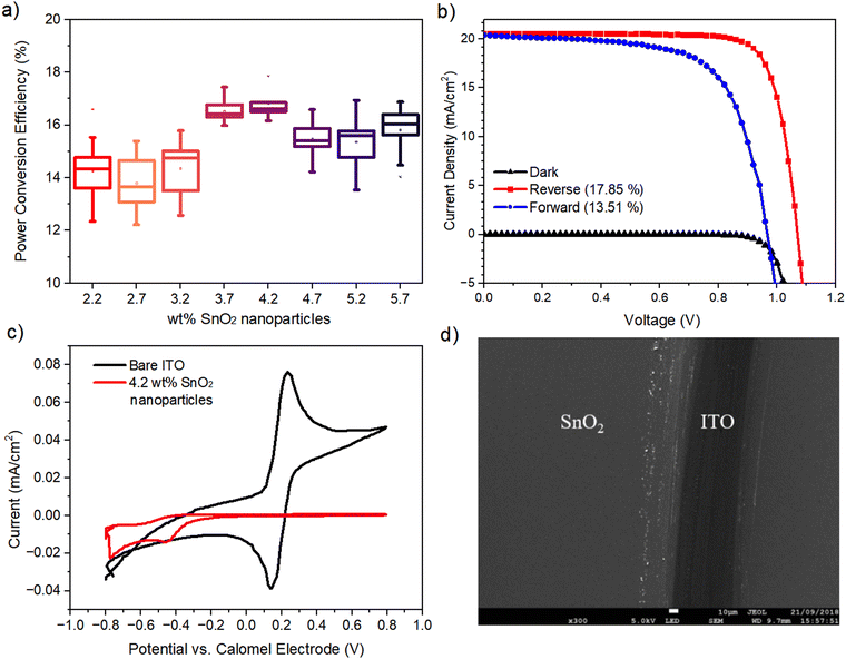
In order to understand and benchmark the behavior of the SnO2 layer prior to slot-die coating, it was necessary to determine the optimized ETL layer characteristics (thickness, morphology and uniformity) to narrow in on a suitable slot-die ink formulation with regard to its wt% and subsequent wet film coating thickness; it should be noted that wt% is used here as an analog to film thickness. This was undertaken using the more familiar spin-coating technique, which has already been proven to give functional and effective SnO2 layers. A planar n–i–p perovskite device with the following architecture is used throughout this work: glass or PET/ITO/SnO2/MAPbI3/Spiro-OMeTAD/Au. SnO2 thickness optimizations were carried out under ambient conditions via spin coating different wt% SnO2 nanoparticles in the range 2.2–5.7 wt%, achieved via dilution of 15 wt% of commercial water with additional DI water, at a set speed of 4000 rpm s−1 onto glass/ITO substrates followed by drying for 10 minutes at 140 °C. An optimal precursor containing 4.2 wt% of SnO2 nanoparticles was found with a film thickness of 50 nm, giving a champion PCE of 17.86%. The corresponding statistical J–V data and champion device J–V curve are shown in Fig. 1(a) and (b) with a Jsc of 20.56 mA cm−2, Voc of 1.07 V and an FF of 81.41%. We note the significant hysteresis observed in our devices for all dilutions of SnO2; however, this is fairly common in planar PSCs due to lower contact area between the ETL and MAPbI3 leading to poor charge extraction.19 Various methods have been tried to mitigate this behavior by improving the interface, but these are beyond the scope of this work.20–22Cyclic voltammetry (CV) was used to determine the “blocking” behavior of the SnO2 films by observing any anodic current produced using a potassium ferri/ferrocyanide redox couple. Fig. 1(c) shows a typical CV trace of a bare ITO film (black trace) producing strong anodic and cathodic current peaks where the electrolyte redox couple is reducing and oxidizing at the ITO surface as voltage is applied. With regard to the SnO2-coated ITO substrate, no anodic current was observed confirming a film with excellent hole blocking behavior. Scanning electron microscopy (SEM) images of the SnO2 film confirm a very homogeneous, defect free layer (Fig. 1(d)).
3.2 Sheet-to-sheet slot-die coating
In order to proceed from spin-coating to the final R2R deposition, an intermediate stage is necessary to identify and understand the coating parameters and operating window using the slot-die coating method. A bench-top S2S slot-die system (FOM) is used, which allows a wide range of input parameters to be varied and output material to be produced on a batch type basis for easy handling and analysis. For the deposition of the SnO2 nanoparticle films, a slot-die coater with a 30 cm long inline convection oven and a moving substrate bed was employed (Fig. 2(a) and (b)). For further preparation for the transition to R2R, the substrate is now switched from glass/ITO to PET/ITO (50 Ohm sq−1), this offers new challenges not only in terms of material handling but also in terms of the condition of the surface as the same manual for washing and cleaning routine used on glass substrates is not possible for the coiled ITO/PET material that is supplied with no cleaning/pre-treatment. The first experimental observation was that direct translation of the material that produced a successful SnO2 films via spin-coating was not possible. Initial trials were inconsistent as the SnO2 nanoparticle did not deposit well onto the PET/ITO; the water-based SnO2 suspension led to poor film morphology owing to the high surface tension of water (72 dynes cm−1), which becomes more challenging not only due to the condition of the ITO/PET surface but also due to the static deposition (slot-die) rather than dynamic deposition (spin-coating). To overcome this, the addition of a low surface tension solvent was explored. The low toxicity short chain alcohols, 1-propanol, 2-propanol (IPA), ethanol and 1-butanol were considered a suitable choice due to their miscibility with water and compatible boiling points.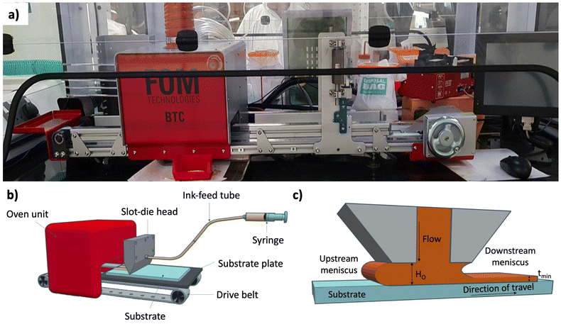 | ||
| Fig. 2 The slot-die sheet-to-sheet system used in this work. (a) Photographic image, (b) schematic and (c) coating head cross-section. | ||
For a 50 nm dry film (as optimized in spin coating), a 5 μm wet film thickness is required and is achieved using a 1.2 wt% concentration of SnO2 calculated using eqn (1).
 | (1) |
 | (2) |
| Solvent | Volume% | σ (Dyn cm−1) | μ (Dyns cm−2) |
|---|---|---|---|
| IPA | 40 | 29.6 | 0.285 |
| Ethanol | 40 | 35.3 | 0.0285 |
| 1-Propanol | 40 | 25.1 | 0.0288 |
| 1-Butanol | 10 | 26.2 | 0.0144 |
A modest speed of 0.25 m min−1 was chosen initially with the intention to increase this in roll-to-roll coatings. The gap height between the meniscus guide protrusions was set as 200 μm, and the use of a meniscus guide with the tab length of 1000 μm led to a head-substrate gap height of 1200 μm in total. We have reported in our previous work the applicability of the low flow limit with meniscus guide coating.23 Plotting the parameters for a range of solvent formulations on the low flow limit model formed the basis of the solvent system chosen for slot-die coating (Fig. S3, ESI†). All four solvent systems, which did not show precipitation (<50 vol%) appear in the stable coating window; therefore to reduce the surface tension for better wet film coatings, the maximum vol% addition of each formulation was selected for coating trials.
Prior to coating, it was deemed important to validate the low flow limit as a good indication of whether the chosen formulations will provide a stable coating. According to the model, a 60 vol% addition of IPA to the SnO2 ink, despite precipitating after 24 h in solution form, will lead to unstable coatings (Fig. 3) and was thus chosen for further scrutiny. This vol% was chosen intentionally in order to illustrate the boundary conditions between a stable and unstable coating regime. In order to visually confirm the stability of the coating, 1 mg ml−1 of pararosaniline acetate dye was added to the inks, ensuring that the viscosity was unchanged. By coating each ink, it was immediately clear that the 60 vol% IPA addition led to significant visible defects confirming the low flow limit prediction. To alleviate the defects, the model suggests that there are two ways to achieve this: reduction of the dimensionless gap (Ho/tmin) or reducing the coating speed, V. Since reduction in coating speed would affect the output manufacturing capacity, we reduced the dimensionless gap by increasing the wet film thickness. Coating a 10 μm layer of the 60 vol% IPA ink led to the removal of the defects observed in the 5 μm wet film, again matching the low flow limit model prediction, producing a stable coating. Additionally, a demonstration of the influence of changing the ink concentration is observed as a decrease from 60 vol% to 40 vol% also transforms the coating into a stable regime.
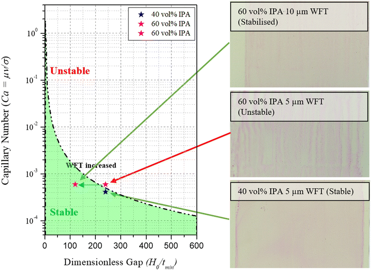 | ||
| Fig. 3 Low flow limit model illustrating coating quality when parameters are in the stable and unstable range. | ||
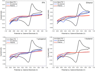
Coating of each solvent system (40 vol% IPA, 40 vol% ethanol, 40 vol% 1-propanol, 10 vol% butanol) was then used on 30 × 10 cm pre-patterned ITO-coated PET substrates at a speed of 0.25 m min−1 and dried in an inline oven, at 140 °C at 0.075 m min−1, giving an overall residence drying time of 4 minutes. Each ink was coated onto an untreated substrate as well as a substrate subjected to 1 minute of plasma treatment. The plasma treatment was employed here for two reasons: first, as a cleaning step and second to determine whether an increase in substrate surface energy would lead to higher quality film formation. Cyclic voltammetry was used to measure the blocking behavior of each of the slot-die-coated layers in order to narrow down the final solvent choice (Fig. 4). The first observation is that plasma treatment of the substrate leads to an improvement in blocking behavior for all solvents apart from the 1-butanol solvent system. The 1-butanol system shows almost perfect blocking qualities on both plasma-treated and -untreated PET substrates, whereas the other three exhibit slightly higher anodic currents, even with a plasma treatment. Thermogravimetric analysis (Fig. S4, ESI†) reveals that although a stable coating is achieved, instabilities occur in the drying phase as the lower boiling point solvents (IPA, 1-propanol and ethanol) exhibit individual mass loss peaks before complete evaporation of the coating. It is likely under these circumstances that the remaining coating reticulates due to the surface energy mismatch causing coating defects and therefore reduction in blocking behavior. However, with 1-butanol having a higher boiling point than water, the 1-butanol evaporates after or with the water meaning that the contact angle of the solution is maintained at a low value throughout the drying process, thus suppressing drying defects.
Although it appeared that adequate blocking layers could be deposited onto plasma cleaned substrates using the lower boiling point solvents, the absence of a plasma cleaning process would be advantageous to the overall capital and processing costs of the SnO2 layer, thus further optimization was carried out using the 1-butanol solvent system.
Finally, the wet film thickness was optimized by increasing it from 5 μm in 2 μm intervals up to 11 μm. In terms of the low flow limit, illustrated in Fig. 3, an increase in WFT is likely to push the coating outcome further into a stable regime. It was found that the optimal wet film thickness was 7 μm which led to a champion PCE of 15.99% and a stabilized efficiency of 11.66%, compared to a stabilized efficiency of 13.24% for a spin-coated film on a glass substrate (Fig. S5 and S6, ESI†).
3.3 Roll-to-roll slot-die coating
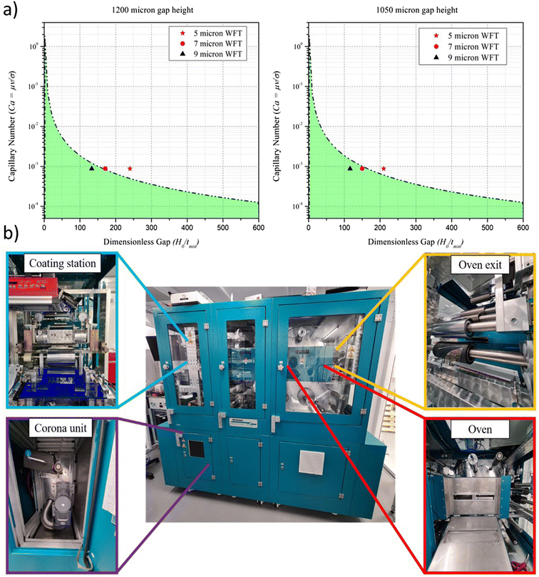
The coating parameters and solution formulation for the optimized blocking behavior are next transferred to a roll-to-roll coating system. One of the key challenges of scaling along with the changes in geometry is the increase in production speed that can be achieved. Therefore, roll-to-roll coating was performed at 1 m min−1 to prove that the speed could be increased to more suitable production speeds without the loss of coating quality. In increasing coating speed from 0.25 to 1 m min−1, the viscocapillary model was updated resulting in a prediction that coating a 5 μm wet film moves into the unstable region, and the 7 μm film sits on the boundary. Reduction of the gap height (Ho) from 1200 to 1050 μm shifted the 7 μm film into the stable region but not the 5 μm film (Fig. 5(a)).Further reduction in this gap height would be difficult to measure accurately. Three wet film thicknesses were coated (5, 7 and 9 μm) onto the substrate at 1 m min−1 and dried in the in-line ovens at 140 with a total residence time of 1 minute. Although predicted to be unstable, the 5 μm film was coated to again see the accuracy of the low flow limit, meaning that the results for this film should be sporadic due to the unstable coating.
The PET roll was removed from the R2R coater, seen in Fig. 5, and unwound, separating each section by the wet film coated. Sections of each film were then cut into 28 × 28 cm squares and the rest of the perovskite device stack spin coated on top. Then, 5 devices (40 pixels) from each film thickness were tested under a solar simulator, shown in Fig. 6(a) and (b). The results from the roll-to-roll coating were in agreement with the S2S coating, in which the optimum performance was achieved by the 7 μm wet film. A champion efficiency of 16.34% was achieved from the slot-die coated film compared to 18.52% for the spin-coated control device (Table 2). The results also proved the validity of the low flow limit, which suggested that the 5 μm wet film had a large variation in performance owing to coating consistency issues. Stabilized efficiency measurements were made on the hero devices for spin-coating and slot-die coating (Fig. 6(c)) and reveal that a small amount of hysteresis was present in both coating methods with average stabilized efficiencies of 13.9% for the spin-coated device and 11.81% for slot-die. An overall difference in PCE of 2.1% between the two coating methods showed that the slot-die coated film gave comparable performances, albeit slightly lower, mostly due to a reduction in fill factor, owing to the resistance of the PET/ITO being over 3 times higher than that of the glass/ITO comparison (15 V 50 Ohm sq−1).
| Deposition | J sc (mA cm−2) | V oc (V) | FF (%) | PCE (%) |
|---|---|---|---|---|
| Spin coated | 20.13 ± 0.46 | 1.06 ± 0.01 | 79 ± 1.08 | 16.8 ± 0.54 |
| S2S Slot-die | 19.38 ± 1.02 | 0.95 ± 0.01 | 73.8 ± 4.4 | 13.5 ± 0.8 |
| R2R Slot-die | 18.9 ± 1.43 | 1.02 ± 0.02 | 69.6 ± 4 | 13.4 ± 1.41 |
Clearly, performance increases are possible by using a lower resistance substrate, optimisation of the perovskite and use of interfacial modifiers. Nonetheless, it was proven that a high-performance roll-to-roll SnO2 film can be deposited via slot-die coating at reasonable coating speeds. In addition to this, the stabilized efficiency was almost identical to the benchtop slot-die-coated film and in fact slightly higher, confirming that the upscaling from sheet-to-sheet to roll-to-roll-coating can be achieved with no loss of performance with careful control of process parameters and use of the low flow limit.
4 Conclusions
This work demonstrates that an efficient ETL of SnO2 can be slot-die coated onto flexible PET substrates under ambient conditions, by low-temperature drying and high throughput capability. Solvent engineering of the coating formulation and the use of the low flow limit are critical to effective coating and drying and therefore forming defect-free blocking layers. Rheology of the solutions was studied and applied to slot-die coating theory by means of the low flow limit, which proved to model real world coating defects well. This model can therefore be used when changing coating parameters, or solution properties, as well as being applicable to subsequent layer deposition, reducing the need for laborious trial and error-type coating trials. Through a full scale up route using low toxicity solvents and therefore having no barrier to industrial scale printing, the formation of an effective, sufficient blocking layer has been maintained. This blocking layer formed on both glass and patterned PET substrates resulted in roll-to-roll-coated SnO2-based perovskite devices with the champion efficiency of 16.34%, thereby leading to only a 11.8% reduction on spin coated glass devices and matching sheet-to-sheet coating.Conflicts of interest
There are no conflicts to declare.Acknowledgements
This work is in part funded by the European Regional Development Fund through the Welsh Government and was supported by the Engineering and Physical Sciences Research Council (EPSRC) through the SPECIFIC Innovation and Knowledge Centre (EP/N020863/1, EP/T028513/1) Self-assembling Perovskite Absorbers—Cells Engineered into Modules Project (EP/M015254/2). This project has received funding from the European Union Horizon 2020 Research and Innovation Programme under the Marie Sklodowska—Curie grant agreement no. 764787. The authors would like to acknowledge the Financial support provided by the M2A that has been made possible through funding from the European Social Fund via the Welsh Government, the Engineering and Physical Sciences Research Council (EP/L015099/1) and Tata Steel Europe that has made this research possible.References
- J. M. Ball and A. Petrozza, Nat. Energy, 2016, 1, 1–13 CrossRef.
- A. Mei, X. Li, L. Liu, Z. Ku, T. Liu, Y. Rong, M. Xu, M. Hu, J. Chen, Y. Yang, M. Gratzel and H. Han, Science, 2014, 345, 295–298 CrossRef CAS PubMed.
- Y. Deng, E. Peng, Y. Shao, Z. Xiao, Q. Dong and J. Huang, Energy Environ. Sci., 2015, 8, 1544–1550 RSC.
- H. Huang, J. Shi, L. Zhu, D. Li, Y. Luo and Q. Meng, Nano Energy, 2016, 27, 352–358 CrossRef CAS.
- Y. Y. Kim, T. Yang, R. Suhonen, M. Välimäki, T. Maaninen, A. Kemppainen, N. J. Jeon and J. Seo, Adv. Sci., 2019, 6, 1802094 CrossRef PubMed.
- F. Mathies, E. J. W. List-Kratochvil and E. L. Unger, Energy Technol., 2020, 8, 1900991 CrossRef CAS.
- J. Troughton, C. Charbonneau, M. J. Carnie, M. L. Davies, D. A. Worsley and T. M. Watson, J. Mater. Chem. A, 2015, 3, 9123–9127 RSC.
- J. Troughton, M. J. Carnie, M. L. Davies, C. Charbonneau, E. H. Jewell, D. A. Worsley and T. M. Watson, J. Mater. Chem. A, 2016, 4, 3471–3476 RSC.
- B. Dou, J. B. Whitaker, K. Bruening, D. T. Moore, L. M. Wheeler, J. Ryter, N. J. Breslin, J. J. Berry, S. M. Garner, F. S. Barnes, S. E. Shaheen, C. J. Tassone, K. Zhu and M. F. A. M. van Hest, ACS Energy Lett., 2018, 3, 2558–2565 CrossRef CAS.
- Y. Galagan, F. Di Giacomo, H. Gorter, G. Kirchner, I. de Vries, R. Andriessen and P. Groen, Adv. Energy Mater., 2018, 8, 1801935 CrossRef.
- K. Hwang, Y. S. Jung, Y. J. Heo, F. H. Scholes, S. E. Watkins, J. Subbiah, D. J. Jones, D. Y. Kim and D. Vak, Adv. Mater., 2015, 27, 1241–1247 CrossRef CAS PubMed.
- D. Burkitt, R. Patidar, P. Greenwood, K. Hooper, J. McGettrick, S. Dimitrov, M. Colombo, V. Stoichkov, D. Richards, D. Beynon, M. Davies and T. Watson, Sustainable Energy Fuels, 2020, 4, 3340–3351 RSC.
- R. Søndergaard, M. Hösel, D. Angmo, T. T. Larsen-Olsen and F. C. Krebs, Mater. Today, 2012, 15, 36–49 CrossRef.
- R. Patidar, D. Burkitt, K. Hooper, D. Richards and T. Watson, Mater. Today Commun., 2020, 22, 100808 CrossRef CAS.
- Q. Jiang, X. Zhang and J. You, Small, 2018, 14, 1801154 CrossRef PubMed.
- T. Bu, J. Li, F. Zheng, W. Chen, X. Wen, Z. Ku, Y. Peng, J. Zhong, Y.-B. Cheng and F. Huang, Nat. Commun., 2018, 9, 4609 CrossRef PubMed.
- D. Yang, R. Yang, K. Wang, C. Wu, X. Zhu, J. Feng, X. Ren, G. Fang, S. Priya and S. Liu, Nat. Commun., 2018, 9, 3239 CrossRef PubMed.
- M. S. Carvalho and H. S. Kheshgi, AIChE J., 2000, 46, 1907–1917 CrossRef CAS.
- L. Xiong, M. Qin, C. Chen, J. Wen, G. Yang, Y. Guo, J. Ma, Q. Zhang, P. Qin and S. Li, et al. , Adv. Funct. Mater., 2018, 28, 1706276 CrossRef.
- K.-H. Jung, J.-Y. Seo, S. Lee, H. Shin and N.-G. Park, J. Mater. Chem. A, 2017, 5, 24790–24803 RSC.
- D. Yang, R. Yang, K. Wang, C. Wu, X. Zhu, J. Feng, X. Ren, G. Fang, S. Priya and S. F. Liu, Nat. Commun., 2018, 9, 1–11 CrossRef PubMed.
- N. Zhu, X. Qi, Y. Zhang, G. Liu, C. Wu, D. Wang, X. Guo, W. Luo, X. Li and H. Hu, et al. , ACS Appl. Energy Mater., 2019, 2, 3676–3682 CrossRef CAS.
- D. Burkitt, P. Greenwood, K. Hooper, D. Richards, V. Stoichkov, D. Beynon, E. Jewell and T. Watson, MRS Adv., 2019, 4, 1399–1407 CrossRef CAS.
Footnote |
| † Electronic supplementary information (ESI) available. See DOI: https://doi.org/10.1039/d2ma00841f |
| This journal is © The Royal Society of Chemistry 2022 |

