 Open Access Article
Transparent thermal insulation ceramic aerogel materials for solar thermal conversion†
Lu
An
 a,
Zheng
Li
 a,
Zipeng
Guo
 c,
Yong
Hu
a,
Yulong
Huang
a,
Jason N.
Armstrong
a,
Chi
Zhou
c and
Shenqiang
Ren
 *abd
*abd
aDepartment of Mechanical and Aerospace Engineering, University at Buffalo, The State University of New York, Buffalo, NY 14260, USA. E-mail: shenren@buffalo.edu
bDepartment of Chemistry, University at Buffalo, The State University of New York, Buffalo, NY 14260, USA
cDepartment of Industrial and Systems Engineering, University at Buffalo, The State University of New York, Buffalo, NY 14260, USA
dResearch and Education in Energy, Environment & Water (RENEW) Institute, University at Buffalo, The State University of New York, Buffalo, NY 14260, USA
First published on 6th September 2022
Abstract
Thermal management in energy-efficient solar thermal energy conversion and transparent windows requires advanced materials with low thermal conductivity and high transparency, such as transparent silica aerogel materials. However, the large scatter domains in porous silica materials would deteriorate their optical transparency. Herein, we report transparent silica aerogels by controlling hydrolyzation and meanwhile silylation modification to enhance the integrity of the microstructure under ambient pressure drying. The transparent silica aerogel materials show a broad-spectrum transparency of 70% from 400 nm and 800 nm, showing promising applications in transparent windows and solar thermal energy conversion systems. The scalability for transparent windows could be achieved with a composite material by incorporating transparent polymeric materials. The solar receiver coupled with a transparent silica aerogel could reach 122 °C within 12 min at a solar irradiance of 1 Sun, ∼200% higher than that in the ambient atmosphere. The engineered structure of the transparent porous silica backbone provides a pathway for solar thermal systems and transparent window applications.
Introduction
Each year, over 627 TW h of energy in the United States is converted from fossil fuel sources to thermal energy,1 while its environmental impact motivates an alternative pathway towards solar thermal generation.2–6 Effective thermal management is critical for energy-efficient solar thermal applications, which requires advanced thermal management materials.2,7,8 In this context, transparent silica aerogel materials show great promise in solar thermal conversion,3 since they show high solar light transmission and heat loss suppression due to their transparent porous microstructure. Optical transparency and thermal insulation are two important aspects of solar thermal systems and window materials.9–13 Compared with conventional transparent glass materials, silica aerogels have high-volume nanoporous structures, which bring unique properties such as lightweight (density of 0.01–0.1 g cm−3) and ultra-low thermal conductivity (as low as 15 mW m−1 K−1 under ambient conditions). Thus, silica aerogels are ideal for thermal and acoustic insulators. Furthermore, the fabrication costs of glass materials are very high, and also the fabrication involves prolonged heat treatment, consuming a significant amount of energy. On the other hand, by adopting the low-cost ambient pressure drying process, the fabrication costs of transparent silica aerogels can be significantly saved. However, silica aerogels are generally mechanically brittle due to their necklace microstructure with weak interparticle bonding,14 and maintaining high thermal insulation together with high optical transparency is still challenging in aerogel materials.15 Thus, it is crucial to achieve transparent and mechanically robust silica aerogels while exhibiting low thermal conductivity.In this study, we report a synthetic strategy to manufacture transparent thermal insulation silica aerogel materials, achieving a low thermal conductivity of 18 mW m−1 K−1, and visible transparency (a broad-spectrum transparency of 70% from 400 nm and 800 nm). The solvent exchange process facilitates their optical transparency while hydrophobic surface modification resists the pore collapse during ambient pressure drying and maintains their structural integrity. The high visible light transparency, low thermal conductivity, together with soundproofing of 8% lower sound intensity, and the scalable manufacturing with the incorporation of a transparent polymer demonstrate their potential applications in transparent window materials. Meanwhile, the solar receiver coupled with a transparent silica aerogel could reach 122 °C within 12 min at a solar irradiance of 1 Sun, ∼200% higher than that in the ambient atmosphere. The engineered structure of the transparent porous silica backbone provides a pathway for solar thermal systems and transparent window applications.
Materials and methods
Materials
The chemicals used in this work were tetraethoxysilane (TEOS), urea (CH4N2O; 98%|Beantown Chemical), hydrogen chloride (HCl), cetyl trimethyl ammonium bromide (CTAB), Mesitylene (TMB), ethanol, trimethylchlorosilane (TMCS), and n-hexane.Synthesis process of T-Aero
CTAB, urea, and TMB were completely dissolved in DI water. Afterwards, TEOS was added and the molar ratio of TEOS![[thin space (1/6-em)]](https://www.rsc.org/images/entities/char_2009.gif) :
:![[thin space (1/6-em)]](https://www.rsc.org/images/entities/char_2009.gif) CTAB
CTAB![[thin space (1/6-em)]](https://www.rsc.org/images/entities/char_2009.gif) :
:![[thin space (1/6-em)]](https://www.rsc.org/images/entities/char_2009.gif) urea
urea![[thin space (1/6-em)]](https://www.rsc.org/images/entities/char_2009.gif) :
:![[thin space (1/6-em)]](https://www.rsc.org/images/entities/char_2009.gif) TMB
TMB![[thin space (1/6-em)]](https://www.rsc.org/images/entities/char_2009.gif) :
:![[thin space (1/6-em)]](https://www.rsc.org/images/entities/char_2009.gif) H2O was kept constant at 1
H2O was kept constant at 1![[thin space (1/6-em)]](https://www.rsc.org/images/entities/char_2009.gif) :
:![[thin space (1/6-em)]](https://www.rsc.org/images/entities/char_2009.gif) 0.122
0.122![[thin space (1/6-em)]](https://www.rsc.org/images/entities/char_2009.gif) :
:![[thin space (1/6-em)]](https://www.rsc.org/images/entities/char_2009.gif) 2.21
2.21![[thin space (1/6-em)]](https://www.rsc.org/images/entities/char_2009.gif) :
:![[thin space (1/6-em)]](https://www.rsc.org/images/entities/char_2009.gif) 0.063
0.063![[thin space (1/6-em)]](https://www.rsc.org/images/entities/char_2009.gif) :
:![[thin space (1/6-em)]](https://www.rsc.org/images/entities/char_2009.gif) 49.25, respectively. The samples with initial pH values of 6.5, 3.2, 2.8, 2.5, and 2.2 are studied by adding HCl (37 wt%) into the solution. The solution (20 mL) was transferred into a sealed plastic container for gelation and aging, lasting for 24 hours in an oven under 60 °C. Urea could be decomposed into ammonia for promoting the pH during the gelation process. The organic chemical residues in gel could be removed with EtOH which was replaced every 8 hours for 1 day. Before ambient pressure drying through a pinhole under 60 °C, the gels were surface silylation modified with a volume of ethanol/TMCS/n-hexane (1
49.25, respectively. The samples with initial pH values of 6.5, 3.2, 2.8, 2.5, and 2.2 are studied by adding HCl (37 wt%) into the solution. The solution (20 mL) was transferred into a sealed plastic container for gelation and aging, lasting for 24 hours in an oven under 60 °C. Urea could be decomposed into ammonia for promoting the pH during the gelation process. The organic chemical residues in gel could be removed with EtOH which was replaced every 8 hours for 1 day. Before ambient pressure drying through a pinhole under 60 °C, the gels were surface silylation modified with a volume of ethanol/TMCS/n-hexane (1![[thin space (1/6-em)]](https://www.rsc.org/images/entities/char_2009.gif) :
:![[thin space (1/6-em)]](https://www.rsc.org/images/entities/char_2009.gif) 1
1![[thin space (1/6-em)]](https://www.rsc.org/images/entities/char_2009.gif) :
:![[thin space (1/6-em)]](https://www.rsc.org/images/entities/char_2009.gif) 8) for 24 h.16,17 On the other hand, the unwashed organic residue in dried samples could be removed by sintering treatment (600 °C for 1 h) while the carbon dioxide sealed inside could maintain the porous microstructures.
8) for 24 h.16,17 On the other hand, the unwashed organic residue in dried samples could be removed by sintering treatment (600 °C for 1 h) while the carbon dioxide sealed inside could maintain the porous microstructures.
Characterization
The microstructures of the samples are imaged using a Carl Zeiss AURIGA scanning electron microscope (SEM) and a JEOL 2010 high-resolution transmission electron microscope (HRTEM). Thermogravimetric analysis (TGA) is performed on a TA instruments SDT Q600. Fourier Transform Infrared (FTIR) spectra are acquired in attenuated total reflection mode (ATR-FTIR spectroscopy) with a Bruker VERTEX 70 on a ZnSe substrate, and atmospheric compensation is implemented during the measurement. A Tristar II 3020 (Micromeritics Corp. Atlanta, GA) is used for Brunauer–Emmett–Teller (BET) analysis measurements. The pure aerogels are degassed at 200 °C for 2 hours before measurement. The specific surface area (SSA) and the pore size distributions are obtained from the low-temperature nitrogen adsorption–desorption isotherm measurement. The surface areas are calculated with the BET theory using isotherm adsorption data at P/P0 from 0.05 to 0.30. The pore size is calculated from the adsorption branch based on the Barrett, Joyner, and Halenda (BJH) method and the average pore diameter is obtained using the equation d = 4V/A. The packing bed density of the aerogel sample was obtained by filling it in a cylindrical column of known volume and the density was calculated from its mass to volume ratio. Bulk density (ρb) is defined as the ratio of the aerogel's mass to its volume. A Micromeritics Accu-Pyc II 1340 Gas Pycnometer using helium gas is used for measuring the skeletal density of samples. The porosity of the aerogels is determined as follows, porosity (%) = (1 − ρb/ρs) × 100, where, ρs is the skeletal density, and ρb is the bulk density of the silica aerogel. Thermal conductivity is measured using a home-designed setup following the ASTM C518 standard. The reference calibration is performed on a commercial Cabot aerogel with a known value of thermal conductivity. The acoustic test is performed in a home-customized sound box with a sound insulation material inside and a sound detector from Kasuntest. The hardness is measured using a Durometer A. The transmittance spectra were measured using a UV-visible spectrophotometer (Agilent Cary 7000). The spectral scanning was performed from 900 nm to 400 nm with a data collection interval of 1 nm. The scan rate was 120 nm min−1, and the spectral bandwidth was 4 nm. The distance between the sample and detector was 15 mm. The light illumination was provided by a solar simulation system (Oriel, LCS-100).Results and discussion
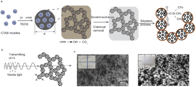
Fig. 1a demonstrates the scheme of the synthetic process of transparent silica aerogel materials (T-Aero) through the sol–gel process of tetraethyl orthosilicate (TEOS) templated by self-assembled cetyl trimethyl ammonium bromide (CTAB) surfactant micelles. The control of the initial pH values is important to obtain a fast hydrolysis rate of TEOS in water inducing homogeneous aggregation with a size dimension smaller than the visible light wavelength.10,18,19 A lower pH has a faster hydrolysis rate, and thus a smaller domain size could be further frozen during the fast gelation process. The gelation process together with the in situ urea foaming addresses the pore collapsing issue induced by the capillary force.20,21 The mesoporous silica network is created, consisting of silica porous nanoparticles and their backbone. Organic residues could be removed during the solvent exchange process,19 by using ethanol followed by hydrophobic silylation modification using an ethanol/TMCS/n-hexane mixture (1![[thin space (1/6-em)]](https://www.rsc.org/images/entities/char_2009.gif) :
:![[thin space (1/6-em)]](https://www.rsc.org/images/entities/char_2009.gif) 1
1![[thin space (1/6-em)]](https://www.rsc.org/images/entities/char_2009.gif) :
:![[thin space (1/6-em)]](https://www.rsc.org/images/entities/char_2009.gif) 8 volume ratio).16,17 After removing organic residues, optical transparency is improved when the size of homogeneous nanoparticle aggregation is smaller than the wavelength of visible light (Fig. 1b). Fig. 1c compares the microstructures of transparent aerogels after the chemical residue removal by sintering treatment and solvent exchange, respectively. High transparency is achieved in the porous microstructure of uniform smaller nanoparticle domains, while decreased optical transparency results from the larger domains.
8 volume ratio).16,17 After removing organic residues, optical transparency is improved when the size of homogeneous nanoparticle aggregation is smaller than the wavelength of visible light (Fig. 1b). Fig. 1c compares the microstructures of transparent aerogels after the chemical residue removal by sintering treatment and solvent exchange, respectively. High transparency is achieved in the porous microstructure of uniform smaller nanoparticle domains, while decreased optical transparency results from the larger domains.
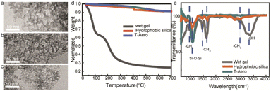
Thermal insulation performance and optical transparency are affected by the nanoporous microstructure and scattering domains. Fig. 2a–c show the homogeneous nanoparticles and small scattering domains of porous silica networks in the optically transparent wet-gel, hydrophobic aerogel and sintered aerogel, respectively, while Fig. 2d shows their corresponding thermogravimetric (TGA) curves. The TGA curve of the wet-gel material indicates a silica weight concentration of 20 wt%, while both hydrophobic and sintered aerogel materials exhibit more than 92 wt% of silica phase. This confirms organic residue removal using solvent exchange and surface modification processes. The hydrophobic silylation modification of the silica aerogel is verified by the peaks corresponding to –CH3 groups in the FTIR spectrum.
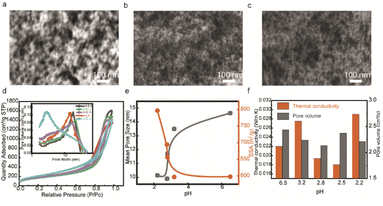
In this work, the initial acidic pH environment could achieve transparent porous silica aerogels, and we studied the samples with different initial acidic pH values. Since the pH value could change the hydrolysis and condensation reactions rate, the morphology of 3D networks would also be changed, which affects the optical transparency and thermal conductivity. The morphologies of transparent silica porous networks under reaction conditions with different initial pH values are shown in scanning electron microscopy (SEM) images (Fig. 3a–c), where the particle sizes decrease as the initial pH values decrease. Thermal insulation performance is related to the pore structures in the networks, and we use the BET technique to compare the pore features of samples with different initial pH values. The N2 adsorption isotherms (type IV) show an H1 hysteresis loop for mesoporous silica networks (Fig. 3d), reflecting the cylindrical pores with uniform diameter distribution. The pore size distribution (the inset in Fig. 3d) from the Barrett, Joyner, and Halenda (BJH) method indicates mesoscale pore sizes smaller than 70 nm to restrain air molecule movement. The mean pore size of porous silica increases, and the specific surface area decreases with increasing pH (Fig. 3e), which is consistent with the morphologies in SEM images (Fig. 3a–c). Fig. 3f compares the thermal conductivity and pore volume of different silica porous networks with different pHs. When there are similar microstructures (open pore with size distribution less than 70 nm, particle sizes and morphologies) in different samples, a higher pore volume indicates a higher porosity, which decreases thermal conductivity. Typically, with decreasing initial pH, the thermal conductivity decreases. The reason for the sample with the initial pH 2.2 having the higher thermal conductivity is probably the aggregated microstructures with an increased solid contact.
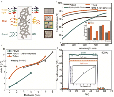
Advanced solar window materials require comprehensive features of visible transparency, thermal insulation, sound resistance, mechanical robustness, and scalable manufacturing. The mechanism for transparent silica aerogels in Fig. 4a depicts how nanoporous structures restrain heat transfer, shield sound waves, and transmit visible light.22–25 Light transmission in aerogels is dominated by Rayleigh scattering and the scattering centers are formed by silica particles and air pockets (Fig. 4a), and thus the transparency of silica aerogels is affected by their nanoporous morphologies.25–27Fig. 4b compares the transparency of the corresponding aerogel samples. Through a quick hydrolysis and condensation process together with a solvent exchange step, the wet-gel ensures small and uniform scattering centers with a transmittance of above 65% for the entire visible wavelength range. The post-sintering treatment could further improve the transmittance above 70% for the entire visible light wavelength range. To enable large-scale transparent insulation materials for solar windows, the polydimethylsiloxane (PDMS) polymer is incorporated into the rapid-prototyped transparent silica aerogel composites. The optical images show the composites composed of PDMS and transparent silica aerogels. The transmittance could be retained at 65% at 700 nm wavelength. The temperature resistance of the different samples shown in Fig. 4c shows that the transparent silica has better thermal resistance than that of pure PDMS, while the transparent composite maintained a good thermal resistance. The temperature difference (ΔT) for transparent silica increases from 6 °C to 13 °C with thickness increasing from 2 mm to 7 mm, almost 3 °C higher than that of pure PDMS at a similar thickness. In addition, nanoporous networks in transparent silica aerogels (T-Aero) could effectively absorb and reflect the sound wave, and Fig. 4d shows the soundproof performance of samples with different thicknesses (0, 3, and 6 mm) under a sound intensity of 500 Hz. The inset demonstrates the roughly linear thickness dependence of soundproof performance, and the sound resistance could be 5 dB at a thickness of 3 mm under a frequency of 500 Hz. The durometer tests in Fig. S6† demonstrate a mechanical robust transparent silica material (92 Shore A), and meanwhile the other samples cannot be measured due to the fragile nature.
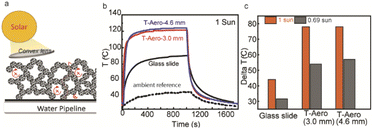
High transparency and low thermal conductivity of porous silica aerogels are ideal for solar thermal systems, and they simultaneously improve the solar energy transmission efficiency and thermal insulation.2,28–30Fig. 5a shows the scheme of solar thermal management; the convex lens is above the transparent silica with an absorbent sheet below while solar energy could be confined to suppress thermal loss. The small particles and pores allow the transmission of solar wavelengths, which is critical for solar thermal applications. Fig. 5b shows the temperature response of the absorbers with T-Aero and a glass slide under one sun illumination. When the temperature induced by the solar simulator (1 sun intensity) is 44 °C, the temperature below the solar thermal system composed of the T-Aero sample (3 mm thickness), absorbent tape, and convex lens could increase the solar thermal temperature to 122 °C, compared with 88 °C using a glass slide in the system. Fig. 5c shows the delta T (temperature difference) for the samples in the solar thermal system under different light intensities (1 Sun and 0.69 Sun). Under 1 Sun condition, the delta T for T-Aero (3 mm) is 78 °C as compared with 44 °C for the glass slide. When the solar intensity reduces to 0.69 Sun, the delta T for T-Aero (3 mm) decreases to 54 °C (69% compared with 1 Sun), while the delta T for glass reduces to 44 °C.
Conclusions
In summary, transparent silica aerogel materials show a broad-spectrum transparency of 70% from 400 nm to 800 nm, a thermal conductivity of 18 mW m−1 K−1, a soundproof performance of 8% lower sound intensity at a frequency of 500 Hz, and scalability through incorporating a transparent polymer (e.g., PDMS), providing promising opportunities for applications in transparent window materials. The solar receiver coupled with a transparent silica aerogel could reach 122 °C within 12 min at a solar irradiance of 1 Sun, ∼200% higher than that in the ambient atmosphere. The engineered structure of the transparent porous silica backbone provides a pathway for solar thermal systems and transparent window applications.Conflicts of interest
The authors declare no competing financial interest.Acknowledgements
This work at University at Buffalo is supported by the U.S. Department of Energy's Office of Energy Efficiency and Renewable Energy (EERE) under the Building Technology Office (BTO) Award Number DE-EE0008675.Notes and references
- P. Kurup and C. Turchi, Initial Investigation into the Potential of CSP Industrial Process Heat for the Southwest United States, National Renewable Energy Lab.(NREL), Golden, CO (United States), 2015 Search PubMed.
- L. Zhao, B. Bhatia, S. Yang, E. Strobach, L. A. Weinstein, T. A. Cooper, G. Chen and E. N. Wang, ACS Nano, 2019, 13, 7508–7516 CrossRef CAS PubMed.
- Z. J. Berquist, A. J. Gayle, N. P. Dasgupta and A. Lenert, Adv. Funct. Mater., 2022, 32, 2108774 CrossRef CAS.
- K. Zhao, H. Jin, Z. Gai and H. Hong, Appl. Energy, 2022, 309, 118508 CrossRef.
- Y. Pang, J. Zhang, R. Ma, Z. Qu, E. Lee and T. Luo, ACS Energy Lett., 2020, 5, 437–456 CrossRef CAS.
- T. Ding and G. W. Ho, Joule, 2021, 5, 1639–1641 CrossRef.
- D. Real, R. Johnston, J. Lauer, A. Schicho and N. Hotz, Sol. Energy, 2014, 108, 421–431 CrossRef.
- T. Beikircher, M. Möckl, P. Osgyan and G. Streib, Sol. Energy Mater. Sol. Cells, 2015, 141, 398–406 CrossRef CAS.
- F. Hu, L. An, C. Li, J. Liu, G. Ma, Y. Hu, Y. Huang, Y. Liu, T. Thundat and S. Ren, Cell Rep. Phys. Sci., 2020, 1, 100140 CrossRef CAS.
- L. An, M. Di Luigi, D. Petit, Y. Hu, Y. Chen, J. N. Armstrong, Y. C. Li and S. Ren, ACS Appl. Nano Mater., 2022, 5, 2655–2663 CrossRef CAS.
- Z. J. Berquist, K. K. Turaczy and A. Lenert, ACS Nano, 2020, 14, 12605–12613 CrossRef CAS.
- A. Lamy-Mendes, A. D. R. Pontinha, P. Alves, P. Santos and L. Durães, Construct. Build. Mater., 2021, 286, 122815 CrossRef CAS.
- D. M. Butts, P. E. McNeil, M. Marszewski, E. Lan, T. Galy, M. Li, J. S. Kang, D. Ashby, S. King, S. H. Tolbert, Y. Hu, L. Pilon and B. S. Dunn, MRS Energy Sustain., 2021, 7, 39 CrossRef.
- M. Marszewski, A. Dashti, P. E. McNeil, M. Fox, V. Wall, D. M. Butts, S. C. King, G. N. Kashanchi, S. H. Tolbert, B. Dunn and L. Pilon, Microporous Mesoporous Mater., 2022, 330, 111569 CrossRef CAS.
- J. Wang, D. Petit and S. Ren, Nanoscale Adv., 2020, 2, 5504–5515 RSC.
- S.-W. Hwang, H.-H. Jung, S.-H. Hyun and Y.-S. Ahn, J. Sol-Gel Sci. Technol., 2007, 41, 139–146 CrossRef CAS.
- A. V. Shlyakhtina and Y.-J. Oh, J. Non-Cryst. Solids, 2008, 354, 1633–1642 CrossRef CAS.
- X. Ji, Y. Du and X. Zhang, Adv. Mater., 2022, 34, 2107168 CrossRef CAS PubMed.
- K. Kanamori, M. Aizawa, K. Nakanishi and T. Hanada, Adv. Mater., 2007, 19, 1589–1593 CrossRef CAS.
- R. Yang, F. Hu, L. An, J. Armstrong, Y. Hu, C. Li, Y. Huang and S. Ren, Nano Lett., 2019, 20, 1110–1116 CrossRef PubMed.
- X. Han, K. T. Hassan, A. Harvey, D. Kulijer, A. Oila, M. R. C. Hunt and L. Šiller, Adv. Mater., 2018, 30, 1706294 CrossRef PubMed.
- Z. Mazrouei-Sebdani, H. Begum, S. Schoenwald, K. V. Horoshenkov and W. J. Malfait, J. Non-Cryst. Solids, 2021, 562, 120770 CrossRef CAS.
- C. Mandal, S. Donthula, R. Soni, M. Bertino, C. Sotiriou-Leventis and N. Leventis, J. Sol-Gel Sci. Technol., 2019, 90, 127–139 CrossRef CAS.
- S. C. King, M. Li, T. Galy, Y. Yan, J. S. Kang, V. M. Basile, Y. L. Li, M. Marszewski, L. Pilon, Y. Hu and S. H. Tolbert, J. Phys. Chem. C, 2020, 124, 27442–27452 CrossRef CAS.
- A. J. Hunt, Light-scattering Studies of Silica Aerogels, Lawrence Berkeley Lab, CA (USA), 1983 Search PubMed.
- A. Emmerling, R. Petricevic, A. Beck, P. Wang, H. Scheller and J. Fricke, J. Non-Cryst. Solids, 1995, 185, 240–248 CrossRef CAS.
- Y. Du, X. Zhang, J. Wang, Z. Liu, K. Zhang, X. Ji, Y. You and X. Zhang, ACS Nano, 2020, 14, 11919–11928 CrossRef CAS.
- K. McEnaney, L. Weinstein, D. Kraemer, H. Ghasemi and G. Chen, Nano Energy, 2017, 40, 180–186 CrossRef CAS.
- S. Svendsen, J. Non-Cryst. Solids, 1992, 145, 240–243 CrossRef CAS.
- A. A. Günay, H. Kim, N. Nagarajan, M. Lopez, R. Kantharaj, A. Alsaati, A. Marconnet, A. Lenert and N. Miljkovic, ACS Appl. Mater. Interfaces, 2018, 10, 12603–12611 CrossRef PubMed.
Footnote |
| † Electronic supplementary information (ESI) available. See https://doi.org/10.1039/d2na00412g |
| This journal is © The Royal Society of Chemistry 2022 |

