 Open Access Article
Growth mechanisms from tetrahedral seeds to multiply twinned Au nanoparticles revealed by atomistic simulations†
El yakout
El koraychy
a,
Cesare
Roncaglia
 a,
Diana
Nelli
a,
Manuella
Cerbelaud
a,
Diana
Nelli
a,
Manuella
Cerbelaud
 b and
Riccardo
Ferrando
 *c
*c
aDipartimento di Fisica dell'Università di Genova, via Dodecaneso 33, Genova, 16146, Italy
bUniversité de Limoges, CNRS, IRCER, UMR 7315, F-87000 Limoges, France
cDipartimento di Fisica dell'Università di Genova and CNR-IMEM, via Dodecaneso 33, Genova 16146, Italy. E-mail: ferrando@fisica.unige.it
First published on 20th June 2022
Abstract
The growth pathways from tetrahedral to multiply twinned gold nanoparticles in the gas phase are studied by molecular dynamics simulations supported by density functional theory calculations. Our results show that the growth from a tetrahedron to a multiple twin can take place by different pathways: directly from a tetrahedron to a decahedron (Th → Dh pathway), directly from a tetrahedron to an icosahedral fragment (Th → Ih), and from a tetrahedron to an icosahedron passing through an intermediate decahedron (Th → Dh → Ih). The simulations allow to determine the key atomic-level growth mechanism at the origin of twinning in metal nanoparticles. This mechanism is common to all these pathways and starts from the preferential nucleation of faulted atomic islands in the vicinity of facet edges, leading to the formation and stabilization of twin planes and of fivefold symmetry axes.
New conceptsMultiply twinned particles (MTPs) are nanoparticles composed of tetrahedra joined by twin planes. Well known types of MTPs are decahedra and icosahedra, where the tetrahedra are arranged around fivefold axes. These structures can develop by growth from a single tetrahedron, as also shown by recent experiments in which the complete pathways from the elementary unit to the different types of MTPs were observed. In spite of the numerous experimental observations, the interpretation of the growth pathways from tetrahedra to MTPs is a long-standing open problem, since the atomic-level mechanisms responsible for twinning and growth pathway differentiation are still unclear. Our molecular dynamics simulations of the growth of gold nanoparticles reveal the two key mechanisms at the origin of these processes. The first mechanism is the formation of specific metastable defects on the surface of the initial tetrahedron. The second mechanism is the stabilization of those defects that cause the necessary symmetry breaking and the subsequent nucleation of fivefold axes, around which cyclic twinning develops. We demonstrate that twinning can take place in the gas phase without the intervention of ligands or surfactants, by mechanisms common to several metals besides gold. |
Among various types of nanomaterials, gold promises to play a crucial role in the fields of photonic, catalytic, sensing, and hydrogen storage devices, because of its optical properties, enhanced catalytic activities and electrical conductivity.1–6 These properties can be improved even more when the shape of the gold nanoparticles is controlled to produce multiply twinned morphology. Common forms of multiply twinned structures are the 5-fold or 20-fold twinning of tetrahedra (Th), which correspond to decahedra (Dh) and icosahedra (Ih), respectively. Multiply twinned particles (MTPs) are found in a wide range of materials7–12 and they are particularly interesting due to their crystallographically forbidden pentagonal symmetry and concomitant lattice strain. Strain has been shown to have a major effect on surface reactivity offering an exciting opportunity to tailor the catalytic properties by surface strain engineering.13–17
Recently, the fabrication of MTPs with tailored structures and properties has received great attention. However, in spite of numerous experimental data, the physical mechanisms responsible for the formation of twin boundaries and of particles with cyclic fivefold twinning are still a controversial subject.18–21 In ref. 18, it was observed that these particles can form through successive growth twinning, in which a single crystalline tetrahedral seed develops twin defects to yield an MTP structure. As noted in ref. 21, this requires a symmetry breaking of the tetrahedral structure whose atomic-level origin is still an open problem. There are further steps in the growth of MTPs from tetrahedra that are not yet understood at the atomic level. These steps comprise the subtle mechanisms behind the nucleation of a new fivefold axis, and the growth pathways of tetrahedra around that fivefold axis.
The objective of this Communication is to shed light on these open issues, by unravelling the atomic-level physical mechanisms at the origin of twinning in metal nanoparticles. Our results show that:
(i) The growth of pure gold MTPs from an initial tetrahedron can occur in the gas phase, without the action of surfactants or passivating agents.
(ii) The nucleation of a fivefold axis is triggered by the stabilization of specific defects, i.e. two faulted (hcp stacking) islands on the two sides of the same edge. Faulted islands form because of the preferential adatom placement on hcp sites at facet edges.
(iii) The growth of the four new tetrahedra around that fivefold axis to form a decahedron is simultaneous, but with different growth mechanisms and rates depending on their positions with respect to the first tetrahedron.
(iv) The concurrent stabilization of a third faulted island on another facet can start the direct formation of an icosahedral fragment instead of a decahedron.
Nanoparticle growth is simulated by molecular dynamics (MD), which allow to monitor the process atom by atom22, reproducing physical trajectories without any ad hoc assumption about diffusion mechanisms and transition rates. Au nanoparticles are grown starting from tetrahedral seeds of sizes N < 1000 atoms. New atoms are deposited one by one from random directions, with deposition rates rdep between 0.1 and 10 atoms per ns.22,23 Growth temperatures T are between 300 and 500 K, where nanoparticles are solid. MD simulations results are supported by density functional theory (DFT) results (see the ESI†). Au is modelled by the Gupta potential24,25 (see the ESI† for details), which was used to simulate the growth of gas-phase Au clusters up to ∼900 atoms in very good agreement with the experiments.23
In the initial growth stage, adatoms quickly diffuse on the (111) facets of the tetrahedron. These adatoms may either originate from deposition or from detachment of top atoms from sharp tips, which are unstable at room temperature and above, so that a perfect tetrahedron quickly transforms into a slightly truncated tetrahedron. In our model, the diffusion barrier on flat (111) terraces is of 0.12 eV,26 in excellent agreement with recent DFT calculations and experimental estimates.27,28 The adatoms can meet each other and nucleate islands. The most likely adsorption sites for island nucleation are in the close vicinity of facet edges, where adsorption energy is larger by ∼0.1 eV than in the central sites of the facet. This is similar to what was found for Pt/Pt(111).22,29,30 The closest sites to the sharp edges of the tetrahedron are the continuation of the hcp lattice of adsorption sites, so that atomic islands nucleating there are naturally placed on stacking fault.22 Preferential adsorption at edges is the first key step causing symmetry breaking. For this reason, we have checked adsorption energies by DFT calculations (see the ESI,† Table S2), which confirm that hcp sites in the close vicinity of edges are the most favorable, in good agreement with Gupta results.
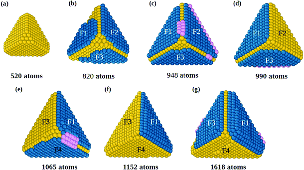
The initial growth stages are better understood by means of Fig. 1, where we report snapshots from a simulation starting from a slightly truncated tetrahedron (Fig. 1(a)). As shown in Fig. 1(b and c), faulted islands can grow on all facets. Between two nearby faulted islands, a groove is formed along their common edge, as between F1 and F2 in Fig. 1(b and c). Adatoms that accumulate in the groove (in pink, Fig. 1(c)) are in principle in the correct position for nucleating a new fivefold axis along the edge. However, the faulted islands are metastable and can easily revert to fcc stacking (for example the island on face F2 in Fig. 1(d)), eliminating the groove and thus continuing tetrahedral growth without nucleating any fivefold axis. In order to nucleate a five fold axis, faulted islands facing the same edge need to be stabilized. Island stabilization occurs when a new atomic layer nucleates on top of a faulted island, as in F1 of Fig. 1(e), locking the island on hcp stacking and starting the formation of a twin boundary. Island stabilization is a second crucial step of the growth pathway. It is necessary for both islands at a common edge, to avoid displacement to fcc stacking (that happened to island F4 in Fig. 1(f)).
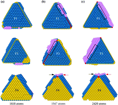
When both hcp islands are stable, as F1 and F3 of Fig. 1(g), also the groove becomes stable so that adatoms can fill it and start the formation of the fivefold axis, as shown in Fig. 2 (see also Fig. S2, ESI†), which continues the simulation of Fig. 1. The groove between islands F1 and F3 (Fig. 2(a)) acts as a trap for adatoms that diffuse on the islands and cross their borders, so that atomic columns begin to form there. These columns (pink atoms in Fig. 2(b)) are parallel to the common tetrahedral edge, and they are at the origin of two further key steps of the growth pathway. First, an atomic column in the groove can cover the edge of the original tetrahedron, which becomes a local fivefold axis (whose end atom is colored in red). Correspondingly, new twin boundaries begin to develop. Second, the columns in the groove create fourfold adsorption sites at the borders of F1 and F3. The fourfold sites are enclosed in the black rectangles in the first and second rows of Fig. 2(b and c); their position is also indicated by the arrows in the third row of the figure. The fourfold sites are traps for adatoms, because adsorption energy is larger than in three-fold sites by about 0.3 eV. These fourfold adsorption sites are of two types, i.e. sites on the groove side (trg sites), and on the terrace side (trt sites). In Fig. 2, trg and trt sites are indicated by black and red arrows, respectively. Adatoms filling trg sites nucleate further atomic columns in the groove, creating at the same time new trt sites on the nearby terrace. On the other hand, adatoms filling trt sites start new layers on the terrace, and create new trg sites. This process is of similar nature to the autocatalytic process causing the growth of tetrahedral Pt nanocrystals from octahedra.22
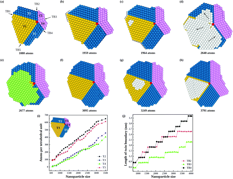
The consequences of this autocatalytic process on further growth steps are shown in Fig. 3, which shows the completion of the Th → Dh growth pathway (see also Fig. S3, ESI†). The initial tetrahedral unit is labelled T1, whereas the other four tetrahedra that will complete the decahedron are labelled T2, T3, T4 and T5. Twin boundaries are labelled from TB1 to TB5. The initial part of the growth (not shown) takes place as in Fig. 1 and 2 up to the stage of Fig. 3(a), which is similar to that of Fig. 2(c). Favorable adsorption sites in Fig. 3(a) are at the bottom of the grooves, in correspondence of the twin boundaries. T2 and T5 grow differently from T3 and T4, because T2 and T5 have to grow only in height, while T3 and T4 have to grow both in height and in width. Let us explain this point by comparing T2 and T3. The completion of T2 takes place by growth in the direction of TB2. When a column nucleates at the re-entrance corresponding to TB2, a new atomic layer is grown on T2 by a step flow mechanism, thus increasing the height of T2 along TB2 direction. On the other hand, the same column also causes the growth of T3 along TB2 direction, but this means that T3 increases its width but not its height. In order to increase the height of T3, growth must proceed along TB3 direction, a process occurring when an atomic column is nucleated at TB3. In this case, step flow takes place on both T3 and T4, since they share the same twin boundary. Snapshots in Fig. 3(c–h) clearly show the step flow mechanisms leading to the growth of the four tetrahedra, in such a way that a well developed decahedron is finally formed. The number of atoms in the four new tetrahedra grows at comparable rates (see Fig. 3(i)), but T3 and T4 start their growth later and, since they need to increase both height and width, their heights grow slower than those of T2 and T5 (see Fig. 3(j)).
During the growth of the Dh, we observe the closing and reopening of re-entrant grooves (see Fig. 3(b–c)) at the ends of twin boundaries (a strain relaxation mechanisms31). Another frequent phenomenon is the capping of the decahedron by a faulted island that cover several tetrahedra. In Fig. 3(d), the faulted island (white atoms) almost completely covers the top facets of T1 and T5, and half of the top facet of T2. The island is one-layer thick, and as such, it is not stabilized, so that it may shift to the correct stacking, as in Fig. 3(e). This hcp → fcc stacking transformation occurs by successive shifts of the parts of the capping island, in the directions indicated by the arrows in Fig. 3(d), starting from the piece on top of T2 and continuing anticlockwise. As previously noted, faulted islands are stabilized by the nucleation of a second layer on top of them. A stabilized faulted island is present in Fig. 3(h).
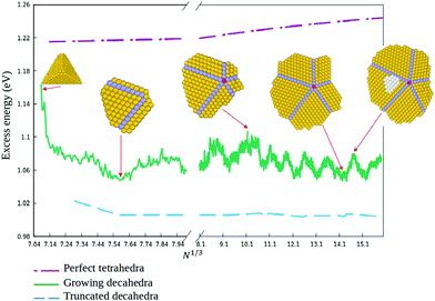
In order to quantitatively monitor decahedral growth, in Fig. 4 we report the size-dependent excess energy Eexc32
 | (1) |
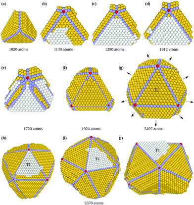
In Fig. 5 we show snapshots of the Th → Ih pathway, directly producing icosahedral fragments with several fivefold axes without passing through a well developed decahedron (see also Fig. S4, ESI†). The initial stages (Fig. 5(a and b)) are of the same type as in Fig. 2: the growing tetrahedron develops two twin planes simultaneously on two (111) facets, leading to the formation of the first fivefold axis, with five tetrahedra growing around it. During the formation of this fivefold axis, the structure becomes more and more strained at the end of the non grooved twin boundary. This strain is released by displacing of some atoms from the sharp edge and tip to the nearby (111) facet of the initial tetrahedron, where they form a third faulted island, which grows by subsequent deposition of atoms (white atoms in Fig. 5(b)) and triggers the fast growth of the tetrahedral tip that has a border in common with it (see Fig. 5(c)).22 The structure then undergoes a grooving process again at this twin boundary through the migration of some low-coordination atoms to the nearby facets. If by chance these atoms move on top of the new faulted island, they may nucleate a second layer on top of it (as in Fig. 5(d)), thus stabilizing this third faulted island. A third twin plane is thus formed, together with a second and a third fivefold axis simultaneously (Fig. 5(e and f)). These new fivefold axes promote the growth of four new tetrahedra between the three twin planes (Fig. 5(f)), leading to a multi-twinned nanoparticle comprising the first tetrahedron plus nine truncated tetrahedral units (Fig. 5(g)). This structure is a half icosahedron. The nine new tetrahedra grow at different rates, since the tetrahedral units on the three (111) facets of the initial tetrahedron grow faster (see Fig. 5(h–j)), because of a large number of favorable adsorption sites at their borders (see Fig. S4 in the ESI† for more details). These results indicate that the direct formation of an icosahedral fragment from an initial tetrahedron starts from the stabilization of three faulted islands, instead of the two needed for the decahedron. On the other hand, when only one faulted island is stabilized, a double tetrahedron (dTh) is formed (Th → dTh pathway, see Fig. S5, ESI†).
Finally we remark that the direct Th → Ih pathway is different from that of ref.33 and 34 for Ag nanoparticles, where icosahedra were formed by growing on pre-formed decahedra (Dh → Ih pathway). A two-step Th → Dh → Ih pathway is indeed observed also in our present simulations (see simulations G5 and G9 in Fig. S6, ESI†).
To quantify the occurrence of the growth pathways, we performed 10 independent MD simulations at rdep= 1 and 10 atoms per ns, for T = 500 K. We deposited on a tetrahedron of 356 atoms up to a final size of 3500 atoms. The complete results are reported in the ESI† (Table S3 and Fig. S6, S7). We find that decahedral growth is favored by the slower deposition rate, while the faster rate favors icosahedra. Structures without fivefold axes are grown at both rdep, but those at the faster rate comprise also irregular shapes besides truncated dTh.
Conclusions
The overall picture arising from our simulations is that the growth of MTPs from tetrahedra occurs via a sequence of key steps. The first step is the nucleation of hcp islands on the (111) facets of the initial tetrahedron, because of favorable adsorption on hcp sites in the closest vicinity of tetrahedral edges. Therefore, the nucleation of small hcp islands is energetically favored, as in the growth of Pt nanocrystals.22 The hcp islands become no longer energetically favorable when they grow big, so that they may revert to the fcc stacking, which would continue tetrahedral growth. On the contrary, if a second layer nucleates on top of a faulted island, the island is locked on hcp stacking and starts the formation of a twin boundary. This is the second key step: when two islands are stabilized, a new fivefold axis may start to nucleate at their common edge where their associated twin planes meet. This is the starting point of the Th → Dh pathway. On the other hand, if three faulted islands are stabilized, three fivefold axes can form along their common edges. These axes meet at a point, so that they can start the direct Th → Ih pathway. Icosahedra can also grow from the stabilization of faulted islands on top of decahedra (Th → Dh → Ih pathway). Our simulation pathways well correspond to pathways experimentally observed in ref. 18, with the exception of those in which tetrahedra are added one at a time. In our simulations, Dh structures are always obtained by five tetrahedra simultaneously growing around the fivefold axis.In order to support the generality of the growth mechanisms of MTPs from tetrahedra, we performed growth simulations for silver and palladium nanoparticles, starting from the same type of initial structures as in gold. Growth sequences from these simulations are reported in the ESI,† Fig. S8–S11. These sequences show that both Ag and Pd nanoparticles qualitatively present the same growth pathways as Au ones, and that these pathways originate from the same type of atomic-level mechanisms.
In summary, our results reproduce different growth pathways of multiply twinned decahedral and icosahedral Au nanoparticles from an initial tetrahedron, which closely resemble the pathways observed in the liquid-phase experiments of ref. 18 for Au MTPs growth by successive twinning. Our results reveal the basic physical mechanisms at the origin of the twinning process. In addition, they show that multiple twins can form from tetrahedra because of the growth kinetics of pure gold, without the intervention of ligands or surfactants. We believe that our identification of the key growth mechanisms for nanoparticles in vacuum is likely to be of great help also in the context of metal nanoparticles grown by wet-chemistry techniques. In fact, we note that the liquid-phase growth experiments of ref. 18 obtained the same type of growth pathways both in the presence and without ligand CTAB. This indicates that the observed growth pathways were likely to originate mainly from the kinetics of pure Au, while other factors played comparatively a minor role.
Author contributions
EE performed and analyzed most of the growth simulations. DN and RF participated to the analysis of the growth simulations. CR made the DFT calculations. MC prepared and tested the GPU version of the code for growth simulations. RF supervised the work. All authors contributed to writing the manuscript.Conflicts of interest
There are no conflicts to declare.Acknowledgements
The authors acknowledge support from the PRIN 2017 project UTFROM of the Italian MIUR and from the Progetto di Eccellenza of the Physics Department of the University of Genoa. The authors acknowledge networking support from the IRN Nanoalloys of CNRS. The authors thank Dr Chloé Minnai for useful discussions.Notes and references
- Y.-H. Chien, C.-C. Huang, S.-W. Wang and C.-S. Yeh, Green Chem., 2011, 13, 1162–1166 RSC.
- I. Pastoriza-Santos, A. Sánchez-Iglesias, F. García de Abajo and L. Liz-Marzán, Adv. Funct. Mater., 2007, 17, 1443–1450 CrossRef CAS.
- M. Turner, V. B. Golovko, O. P. H. Vaughan, P. Abdulkin, A. Berenguer-Murcia, M. S. Tikhov, B. F. G. Johnson and R. M. Lambert, Nature, 2008, 454, 981–983 CrossRef CAS PubMed.
- K. Saha, S. S. Agasti, C. Kim, X. Li and V. M. Rotello, Chem. Rev., 2012, 112, 2739–2779 CrossRef CAS PubMed.
- K. McNamara and S. A. M. Tofail, Phys. Chem. Chem. Phys., 2015, 17, 27981–27995 RSC.
- R. S. Riley and E. S. Day, Wiley Interdiscip. Rev.: Nanomed. Nanobiotechnol., 2017, 9, e1449 Search PubMed.
- L. D. Marks, Rep. Prog. Phys., 1994, 57, 603–649 CrossRef CAS.
- Z. Li, N. Young, M. D. Vece, S. Palomba, R. Palmer, A. Bleloch, B. Curley, R. Johnston, J. Jiang and J. Yuan, Nature, 2008, 451, 46–48 CrossRef CAS PubMed.
- Y. Xia, Y. Xiong, B. Lim and S. Skrabalak, Angew. Chem., Int. Ed., 2009, 48, 60–103 CrossRef CAS PubMed.
- L. Zhang, C. Z. Huang, Y. F. Li and Q. Li, Cryst. Growth Des., 2009, 9, 3211–3217 CrossRef CAS.
- Z. W. Wang and R. E. Palmer, Phys. Rev. Lett., 2012, 108, 245502 CrossRef CAS PubMed.
- C. Liang and Y. Yu, IUCrJ, 2019, 6, 447–453 CrossRef CAS PubMed.
- M. Mavrikakis, B. Hammer and J. K. Nørskov, Phys. Rev. Lett., 1998, 81, 2819–2822 CrossRef.
- L. Gan, R. Yu, J. Luo, Z. Cheng and J. Zhu, J. Phys. Chem. Lett., 2012, 3, 934–938 CrossRef CAS PubMed.
- R. Reske, M. Duca, M. Oezaslan, K. J. P. Schouten, M. T. M. Koper and P. Strasser, J. Phys. Chem. Lett., 2013, 4, 2410–2413 CrossRef CAS.
- M. Luo and S. Guo, Nat. Rev. Mater., 2017, 2, 17059 CrossRef CAS.
- M. J. Walsh, K. Yoshida, A. Kuwabara, M. L. Pay, P. L. Gai and E. D. Boyes, Nano Lett., 2012, 12, 2027–2031 CrossRef CAS PubMed.
- X. Ma, F. Lin, X. Chen and C. Jin, ACS Nano, 2020, 14, 9594–9604 CrossRef CAS PubMed.
- M. Tsuji, M. Ogino, R. Matsuo, H. Kumagae, S. Hikino, T. Kim and S.-H. Yoon, Cryst. Growth Des., 2010, 10, 296–301 CrossRef CAS.
- M. R. Langille, J. Zhang, M. L. Personick, S. Li and C. A. Mirkin, Science, 2012, 337, 954–957 CrossRef CAS PubMed.
- J. S. Du, W. Zhou, S. M. Rupich and C. A. Mirkin, Angew. Chem., Int. Ed., 2021, 60, 6858–6863 CrossRef CAS PubMed.
- Y. Xia, D. Nelli, R. Ferrando, J. Yuan and Z. Y. Li, Nat. Commun., 2021, 12, 3019 CrossRef PubMed.
- D. M. Wells, G. Rossi, R. Ferrando and R. E. Palmer, Nanoscale, 2015, 7, 6498–6504 RSC.
- F. Cyrot-Lackmann and F. Ducastelle, Phys. Rev. B: Condens. Matter Mater. Phys., 1971, 4, 2406–2412 CrossRef.
- R. P. Gupta, Phys. Rev. B: Condens. Matter Mater. Phys., 1981, 23, 6265 CrossRef CAS.
- R. Ferrando and G. Tréglia, Surf. Sci., 1995, 331–333, 920–924 CrossRef CAS.
- L. T. Roling and M. Mavrikakis, Nanoscale, 2017, 9, 15005–15017 RSC.
- P. M. Spurgeon, K. C. Lai, Y. Han, J. W. Evans and P. A. Thiel, J. Phys. Chem. C, 2020, 124, 7492–7499 CrossRef CAS.
- M. Villarba and H. Jónsson, Surf. Sci., 1994, 317, 15–36 CrossRef CAS.
- A. Gölzhäuser and G. Ehrlich, Phys. Rev. Lett., 1996, 77, 1334–1337 CrossRef PubMed.
- L. Marks and L. Peng, J. Phys.: Condens. Matter, 2016, 28, 053001 CrossRef CAS PubMed.
- F. Baletto, R. Ferrando, A. Fortunelli, F. Montalenti and C. Mottet, J. Chem. Phys., 2002, 116, 3856–3863 CrossRef CAS.
- F. Baletto, C. Mottet and R. Ferrando, Phys. Rev. B: Condens. Matter Mater. Phys., 2001, 63, 155408 CrossRef.
- F. Baletto and R. Ferrando, Rev. Mod. Phys., 2005, 77, 371–423 CrossRef CAS.
Footnote |
| † Electronic supplementary information (ESI) available: Description of the Gupta force field and of the growth simulation method; DFT and Gupta results on Au atom adsorption on tetrahedra; complementary results of growth simulations. See DOI: https://doi.org/10.1039/d1nh00599e |
| This journal is © The Royal Society of Chemistry 2022 |

