 Open Access Article
Enhancement of triboelectricity based on fully organic composite films with a conducting polymer†
Moon Hyun Chung ab,
Hyun-Jun Kimb,
Seunghwan Yooab,
Hakgeun Jeong*b and
Kyung-Hwa Yoo
 *a
*a
aDepartment of Physics, Yonsei University, 50 Yonsei-ro, Seodaemun-gu, Seoul 03722, Republic of Korea. E-mail: khyoo@yonsei.ac.kr
bEnergy ICT Convergence Research Department, Energy Efficiency Research Division, Korea Institute of Energy Research, 152 Gajeong-ro, Yuseong-gu, Daejeon 34129, Republic of Korea. E-mail: hgjeong@kier.re.kr
First published on 19th January 2022
Abstract
Triboelectric nanogenerators (TENGs) based on ferroelectric organic materials have advantages of high flexibility, biocompatibility, controllable ferroelectric properties, etc. However, this has limited the electrical output performance due to their lower ferroelectric characteristics than those of inorganic ferroelectric materials. A lot of effort has been made to improve the organic ferroelectric characteristics through composites, surface modifications, structures, etc. Herein, we report TENGs made of ferroelectric composite materials consisting of poly(vinylidene fluoride-co-trifluoroethylene) (PVDF-TrFE) and poly(3,4-ethylenedioxythiophene):poly(styrenesulfonate) (PEDOT:PSS). The composite was prepared by simply blending PVDF-TrFE and PEDOT:PSS with a weight ratio from 0% to 60%. When the ratio was 20%, the ferroelectric-crystalline phase was enhanced and the highest dielectric constant was observed. Accordingly, the TENGs consisting of 20% composite film and polyimide exhibited the best output performance: the maximum open circuit voltage and short circuit current were ∼15 V and ∼2.3 μA at 1 Hz oscillation, respectively. These results indicate that the ferroelectric characteristics of PVDF-TrFE can be enhanced by adding PEDOT:PSS as a nanofiller.
1 Introduction
Triboelectric nanogenerators (TENGs) based on ferroelectric polymers, self-powered energy harvesters, have attracted considerable attention because they can convert low-frequency and irregular mechanical energy to electrical energy. Also, they can be flexible, light-weight, bio-compatible, low-temperature, and solution-processable.1–3 They provide opportunities for application to self-powered electronics, such as the Internet-of-Things, sensors, and wearable and healthcare devices.4–7 TENGs have many harvesting applications, such as mechanical, thermal, magnetic, and solar.8,9 Specifically, a flutter-driven TENG (FTENG) can use small-scale wind energy by utilizing a fluctuating object in the air flow, and it directly converts it to electric energy based on triboelectrification and electrostatic induction.10,11 Moreover, the electrical output performance of TENGs is affected by the ferroelectric characteristics and surface charges. Thus, TENGs of ferroelectric polymer materials afford an improvement through the use of various methods, such as composite materials, structure, relative permittivity, and surface modifications.12,13Among ferroelectric polymer materials, such as polyvinylidene fluoride (PVDF) and its copolymers, are extensively used for TENGs and piezoelectric nanogenerator active films because of their outstanding chemical resistivity, flexibility, biocompatibility, and mechanical and controllable ferroelectric properties.14,15 PVDF has five phases, including α, β, γ, δ, and ε. In particular, the β and γ phases can affect the ferroelectric characteristics and promote the surface charge density. Thus, that phases need to be improved.16,17 The electrical output performance of PVDF is limited owing to its low-ferroelectric properties,18 and PVDF is used to enhance the ferroelectric properties by using its copolymer. Among the copolymers, poly(vinylidene fluoride-co-trifluoroethylene) (PVDF-TrFE), the ferroelectric properties and dielectric are higher than those of PVDF and the others owing to the TrFE monomers.19,20 Thus, they are good candidates as host materials for TENGs.
When it comes to a contact-separation operational mode in TENGs, it can lead to deformation and can cause the wear of the surface during energy harvesting. This can lead to a negative influence on the electrical output performance. The additive materials with nanoscale dimensions adding to the host material that called nanofillers. Through the adequate nanofillers added to the host materials, it can be enhanced physical properties of the host materials. Moreover, this approach involves modifying the bulk properties of materials based on the functionalization of the chemical structure.21,22 Therefore, ferroelectric materials with nanofillers can increase the physical properties and the relative dielectric constant, which plays a significant role in the generation of triboelectric charges.23,24 Inorganics, metal oxide nanoparticles, and conducting materials such as BaTiO3,18 Au,23 AlOx,25 Ag,26 carbon nanotubes,27 polyaniline,28 and so on,29,30 have been utilized as nanofillers in the ferroelectric polymers to enhance their electrical output.
Among the conducting polymers, poly(3,4-ethylenedioxythiophene)–poly(styrenesulfonate) (PEDOT:PSS) has the advantages of a flexible, highly stable, and low-intrinsic thermal conductivity, and can be used in a solution process.31,32 Additionally, it has a higher electrical conductivity than other conducting polymers.33 Hence, PEDOT:PSS has been extensively used for the top and bottom electrodes of devices, buffer layer of optoelectronic devices, and as thermoelectric materials because of the aforementioned properties.34–38 There are some studies has been conducted to fabricate the PEDOT:PSS coated on PVDF-TrFE films, but the characteristics of the composite films have yet to researched.39 We expect that TENG composite films that PEDOT:PSS serves as a nanofiller in PVDF-TrFE.
In this study, we fabricated fully organic materials for TENG films and proposed PEDOT:PSS as a nanofiller in PVDF-TrFE composite films to increase the electrical output performance of the films. Using X-ray diffraction (XRD), Fourier transform infrared (FT-IR), and differential scanning calorimetry (DSC) characterization, we investigated the effect of PEDOT:PSS at different concentrations on PVDF-TrFE composite films, in terms of the ferroelectric crystallization of the phase. We then optimized the PVDF-TrFE/PEDOT:PSS composite by varying the PEDOT:PSS concentration. The electrical output enhancement of the TENG films with PVDF-TrFE/PEDOT:PSS composite films was then measured. The dielectric constants of the PVDF-TrFE films and PVDF-TrFE/PEDOT:PSS composite films were evaluated. Furthermore, we demonstrated an FTENG using PVDF-TrFE/PEDOT:PSS composite films in the presence of air flow.
2 Experimental section
2.1 Materials
PEDOT:PSS (Clevios PH1000) solution was purchased from Heraeus (Germany). PVDF-TrFE (70–30 mol%) copolymer powder and DMF were purchased from Piezotech (France) and Sigma-Aldrich (USA), respectively. A polyethylene terephthalate (PET)/indium tin oxide (ITO) film (125 μm, 60 Ω sq−1) and conductive copper foil tape (Cu tape, thickness = 80 μm) were obtained from Sigma-Aldrich and 3M (USA), respectively. Polyimide tape (PI tape, thickness = 60 μm) was purchased from DupontTM (USA).2.2 Preparation of the PVDF-TrFE/PEDOT:PSS composite films
PVDF-TrFE/PEDOT:PSS composite films were prepared as shown in Fig. S1.† First, the PEDOT:PSS solution in water was dispersed in DMF (10 mL) solvent at a certain fraction (0–60 wt% based on its PVDF-TrFE weight), and PVDF-TrFE copolymer powder (2.5 g) was added to the PEDOT:PSS/DMF solution, followed by stirring at 35 °C for 12 h (Fig. S1a†). To fabricate the PVDF-TrFE/PEDOT:PSS composite films (Fig. S1b†), the composite solution was poured into the silicon square mold with a size of 40 × 40 × 0.1 mm3 (inner 30 × 30 × 0.1 mm3) (width (W) × depth (D) × height (H)) on the PET/ITO, and flattened with a blade. The silicone mold was then peeled off, followed by annealing in a vacuum chamber at 30 °C for 1 h and then at 80 °C for 3 h. Finally, the PET/ITO film that was not covered with the composite film was removed except for the part where the copper wire was connected. The thickness of the composite film measured by using a surface profiler (DektakXT stylus profiler, Bruker, USA) was ∼17 μm.2.3 Fabrication of triboelectric nanogenerator
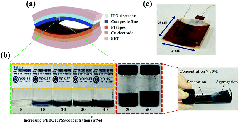
An arch-shaped TENG was fabricated by bending composite film/ITO/PET and PET/Cu tape/PI layers of the same size (contact area: 30 × 30 mm2), and was then sealed at the two short edges with PI tape. Thus, the composite films of PVDF-TrFE/PEDOT:PSS and PI were face to face (Fig. 1a and c). Subsequently, the two electrodes were connected using copper wires.2.4 Fabrication of FTENG
The FTENG was composed of PVDF-TrFE/PEDOT:PSS composite films, a Cu tape electrode, PI films, and polycarbonate (PC). A PC cuboid with inner dimensions of 30 mm × 75 × 30 mm3 (width (W) × depth (D) × height (H)) was made using a laser cutter. PVDF-TrFE/PEDOT:PSS composite films were coated on Cu tape, as described in Section 2.2. A piece of PVDF-TrFE/PEDOT:PSS composite film/Cu tape (30 × 75 mm2) was attached to the PC plates at the top and bottom. Two electrodes were connected using copper wires. The PI film (30 × 75 mm2, 65 μm) was fixed at one end on a bluff body.2.5 Characterization
The surface morphology was confirmed using field emission scanning electron microscope (FE-SEM, JSM-6500F, JEOL, Japan). The structures of the composite films were investigated using XRD (D/max-2500 pc, Rigaku, Japan), FT-IR spectroscopy (Nicolet iS50, Thermo Fisher Scientific Instrument, USA), and DSC (DSC 4000, PerkinElmer, USA). The output performance of the TENG was measured using an oscilloscope (DPO 2002 B, Tektronix, USA), a low-noise current preamplifier (Model SR 570, Stanford Research Systems, Inc., USA), and an electrometer (6517 B, Keithley, USA). A function generator and mechanical wave driver (PI-8127 and SF-9324, PASCO, USA) were used to provide mechanical motion for the TENG. The capacitance of the composite films was measured using an LCR meter (E4980AL capacitance meter, Keysight, USA) in the frequency range of 100 Hz to 300 MHz. The airflow rate was estimated using a hot-wire anemometer (Testo 425, Testo SE & Co. KGaA, Germany).3 Results and discussions
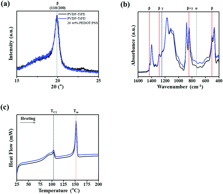
We prepared PVDF-TrFE/PEDOT:PSS composite films with weight ratios in the range of 0–40%. PVDF-TrFE is insoluble in water, and PEDOT:PSS is a water-based solution; thus, when PEDOT:PSS is added at a weight ratio greater than 40%, the solution is aggregated. However, the composite solution with a ratio smaller than 40% was well dispersed, and the film made from the composite solution was semi-transparent (Fig. 1b). The morphology of PVDF-TrFE/PEDOT:PSS composite films was analyzed by FE-SEM as shown in Fig. S2.† It consisted of the surface of rod-like shape. To investigate the effect of PEDOT:PSS on the crystalline phase of PVDF-TrFE, we measured the XRD spectra of the composite films in the 2θ range of 15–25° (Fig. 2a and S3a†). All films yielded a peak at 19.8°, which is associated with the β-phase at the (110) and (200) planes.40,41 These results indicate that the crystallinity of PVDF-TrFE did not significantly affect by adding PEDOT:PSS.Using FT-IR spectroscopy, we investigated the films for the transformation of phases and chain orientation within a wavenumber range of 400–1600 cm−1. The spectra reveal important information about PVDF-TrFE and PVDF-TrFE/PEDOT:PSS composite films on the basis of the presence of the crystalline phase (Fig. 2b and S3b†). Crystallization of the β + γ phase was observed in all the films in the absorption bands at 840 cm−1.42 The strong peak was classified as a characteristic of the β + γ phase, which is a characteristic of CF2 symmetric stretching. In addition, the peaks at 1430 and 1288 cm−1 is attributed to the β phase. The presence of the γ phase was observed at 1235 cm−1. The bands at 763 cm−1 were associated with the α-phase.43,44
Evaluation of the electroactive phase (β + γ phase) fraction (FEA) in the samples was calculated using the Lambert–Beer law eqn (1):45
 | (1) |
 | (2) |
 | (3) |
| PVDF-TrFE | 10 wt% PEDOT:PSS | 20 wt% PEDOT:PSS | 30 wt% PEDOT:PSS | 40 wt% PEDOT:PSS | |
|---|---|---|---|---|---|
| FEA (%) | 76.46 | 73.32 | 70.72 | 66.86 | 62.66 |
| ΧC (%) | 30.10 | 30.82 | 37.11 | 29.08 | 31.30 |
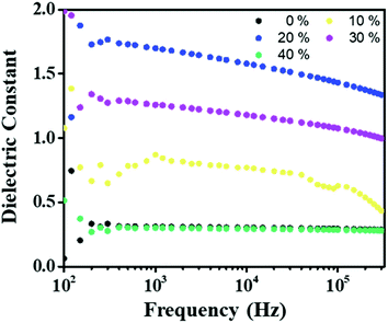 | ||
| Fig. 3 Comparison of the dielectric constant for the PVDF-TrFE/PEDOT:PSS composite films with different PEDOT:PSS concentration from 0% to 40% at 300 K. | ||
| PVDF-TrFE | 10 wt% PEDOT:PSS | 20 wt% PEDOT:PSS | 30 wt% PEDOT:PSS | 40 wt% PEDOT:PSS | |
|---|---|---|---|---|---|
| Thickness (μm) | 17.95 | 17.03 | 16.94 | 16.65 | 16.69 |
| Dielectric constant (at 1 kHz) | 0.31 | 0.87 | 1.70 | 1.25 | 0.30 |
The working mechanism of the fabricated TENG, which includes triboelectrification and electrostatic induction, is shown in Fig. 4. As shown in Fig. 4a, when the composite films and the PI tapes are in contact, the opposite charges are equally generated between the composite and PI tapes of the contact surfaces. The composite films generated more electrically negative charges than the PI tapes.53,54 Releasing the two films, the potential difference drives electrons from the ITO electrode to the Cu electrode (Fig. 4b)The electron flows continually until the maximum value of Vo is reached as the composite films fully separate from the original states (Fig. 4c). In sequence, the electrons are driven from the Cu electrode back to the ITO electrode, decreasing the amount of induced charges when the composite films approach the PI tapes (Fig. 4d). Consequently, an alternating current is generated by the contact and separation modes between the composite films and PI tapes.
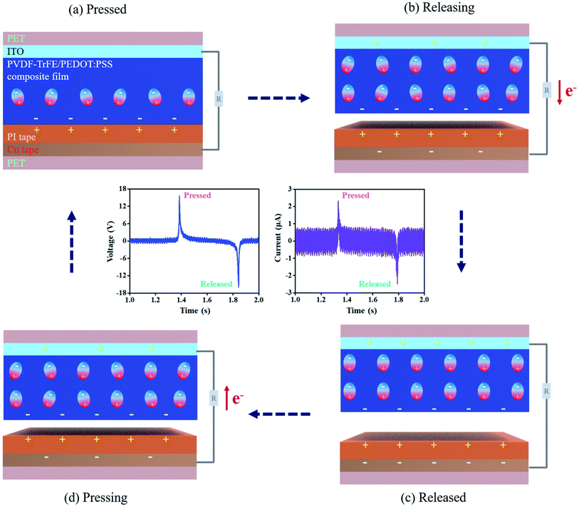 | ||
| Fig. 4 Working mechanism of TENG with the PVDF-TrFE/PEDOT:PSS composite films: (a) pressed, (b) releasing, (c) released and (d) presssing. | ||
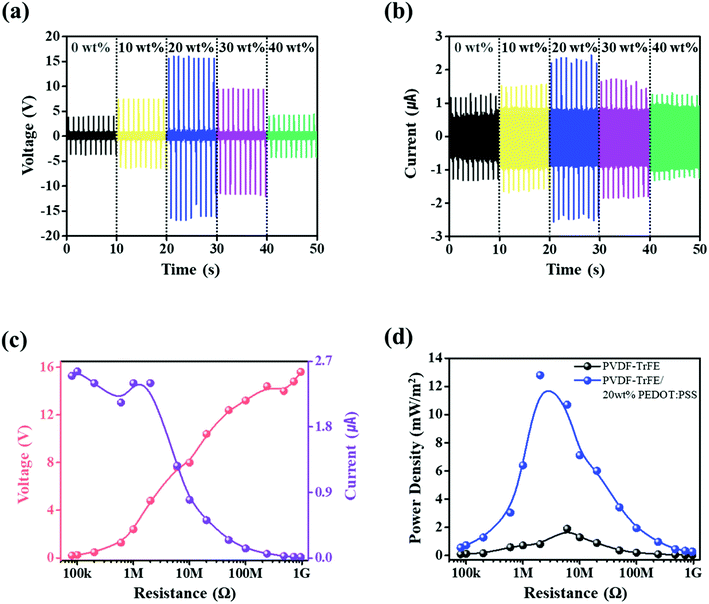
To assess the electrical output performance of the PVDF-TrFE and PVDF-TrFE/PEDOT:PSS composite films, a wave driver was used for the periodic contact and separation modes. The applied tapping force was ∼8 N with 1 Hz oscillation, and the maximum distance of the contact separation was set to 7 mm. Fig. 5a and b shows the open-circuit voltage and closed-circuit current of PVDF-TrFE and PVDF-TrFE/PEDOT:PSS composite piezoelectric films containing different concentrations of PEDOT:PSS. PVDF-TrFE films generated an open-circuit voltage (Vo) equal to 4 V and a short-circuit current (Isc) equal to 1.16 μA. As the concentration of PEDOT:PSS increased, Vo and Isc were observed to increase up to 20 wt% PEDOT:PSS to respective values equal to 15.6 V and 2.32 μA, respectively. For PEDOT:PSS contents above 20 wt%, Vo and Isc decreased. It seems that the predominance of PEDOT:PSS can be attributed to the reduced ferroelectric characteristics. These trends appear similar to the results of the preceding analysis.
The TENG can be explained by an inherent capacitive behavior, and we expected the quantities of triboelectric charges with electrical potential according to eqn (4):55,56
 | (4) |
 | (5) |
As shown in Fig. 5c, to estimate the external load resistance (RL) on the electrical output performance of PVDF-TrFE/20 wt% PEDOT:PSS composite films, Vo and Isc were measured at different RL values from 80 kΩ to 960 MΩ. With the increase of RL, the Vo value of PVDF-TrFE/20 wt% PEDOT:PSS composite films increased from 0.2 to 15.6 V, and the Isc value decreased from 2.3 μA to 160 nA. In addition, the power density was 12.8 mW m−2 at an RL of 2 MΩ (Fig. 5d). Compared with the power density of the PVDF-TrFE films, the maximum power density was shifted by 6 MΩ. These trends were observed at the other PEDOT:PSS contents (Fig. S4, Table S1†). It is thus shown that PEDOT:PSS has an effect on the internal resistance in PVDF-TrFE owing to its conductivity. The free mobile electrons in the conducting polymers have an effect on the movement of electrical charges in PVDF-TrFE.28 Thus, it can be inferred that the composite films can generate more triboelectric charges. However, for contents above 20 wt% PEDOT:PSS, the power density decreased owing to the deterioration of the properties of the ferroelectric.
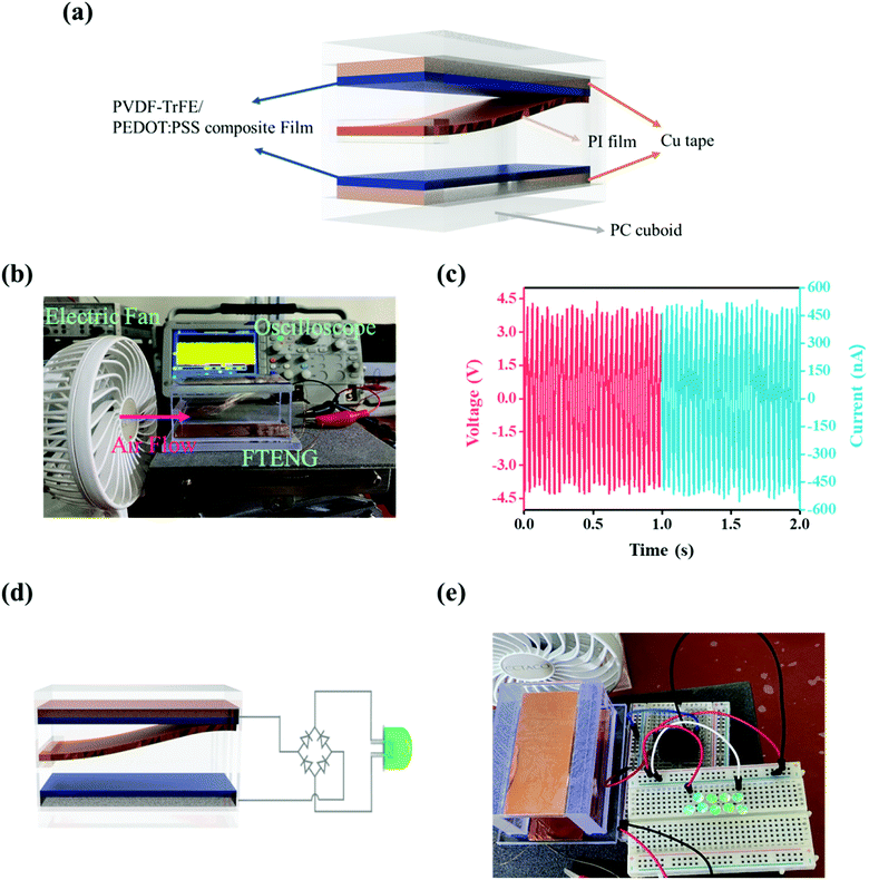
As the frequency of the PVDF-TrFE/20 wt% PEDOT:PSS composite films in the contact-separation mode varied from 1 Hz to 20 Hz (Fig. 6a and b), the corresponding Vo and Isc increased from 15 V to 68 V and from ∼2 μA to ∼23 μA, respectively. The Vo of the TENG should theoretically be constant at various frequencies. We used the wave driver to change the stroke distance between the PVDF-TrFE/PEDOT:PSS composite films and PI tapes with increasing frequency.58 In addition, the capacitance changed and the charge accumulated on the composite films as the contact-separation frequencies increased; this increased the electrical output performance of the TENG.59 The TENG using PVDF-TrFE/20 wt% PEDOT:PSS composite films was used to charge a capacitor from 1 to 1000 μF. The electrical output of the TENG was rectified by a full-bridge diode. The 1 μF capacitor which charged up to 3 V within 25 s (Fig. 6c). To utilize the wind energy, we demonstrated the FTENG. Fig. 7a schematically illustrates the FTENG. The FTENG is shown in Fig. 7b and Video S1.† The Vo and Isc of FTENG using PVDF-TrFE/20 wt% PEDOT:PSS composite films generated 3.7 V and 450 nA, respectively, at an air flow rate of 6.5 m s−1 (Fig. 7c). The electrical output performance of FTENG using PVDF-TrFE films generated a Vo of 1.3 V and an Isc of 210 nA (Fig. S5†). The FTENG was connected to a full-bridge rectifier, and nine commercial green LEDs which were connected in series instantly lit on via the FTENG (Fig. 7d, e and Video S2†). Additional studies in this area are needed to affect the wind velocity, size of the FTENG, and flutter materials.
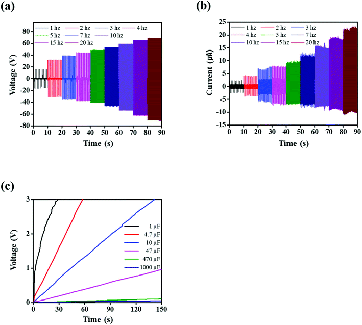 | ||
| Fig. 6 PVDF-TrFE/20 wt% PEDOT:PSS composite films at different oscillations from 1 Hz to 20 Hz: (a) voltage and (b) current. (c) Charging profiles of capacitors at an oscillation of 20 Hz. | ||
The TENG performances of the PVDF-based composite films with nanofillers reported in the previous literatures are listed in Table S2.† The TENG performances would be a change in properties by the host materials with nanofillers or contacting the opposite materials. It can be seen that the PEDOT:PSS is effective nanofillers to enhance the triboelectric properties of PVDF-TrFE. Furthermore, it is expected that it will have the opportunity to be applied as a power supply for a variety of sensors.
4 Conclusions
In summary, we attempted to create all-organic triboelectric composite films with PVDF-TrFE and PEDOT:PSS. The PVDF-TrFE/PEDOT:PSS composite films maintained the characteristics of organic materials while they produced a high-electrical output. PEDOT:PSS was used as a nanofiller and was stably blended with PVDF-TrFE/PEDOT:PSS composite solutions. The effects of PEDOT:PSS at various weight ratios in PVDF-TrFE were investigated using XRD, FT-IR, and DSC. The XRD and FT-IR results showed that the electroactive phase of the composite films was preserved after the addition of different PEDOT:PSS concentrations in PVDF-TrFE. Additionally, the DSC analysis results showed an improvement Χc at different PEDOT:PSS concentrations compared with the PVDF-TrFE films. It seems that PEDOT:PSS affects the conformation of the ferroelectric characteristics. The electrical output performance reached a maximum at a PEDOT:PSS composite film content of 20 wt%, showing an open-circuit voltage of ∼15 V, and a closed-circuit current of ∼2.3 μA for oscillations at 1 Hz. The power density of the PVDF-TrFE/20 wt% PEDOT:PSS composite films was 12.8 mW m−2 at an RL of 2 MΩ, which was shifted to an RL of 6 MΩ for the PVDF-TrFE films. The dielectric constant value increased up to the PVDF-TrFE/30 wt% PEDOT:PSS composite films compared with the PVDF-TrFE films. It can be inferred that PEDOT:PSS has a leverage effect on the ferroelectric characteristics of PVDF-TrFE. Therefore, this led to an increase in the electrical output performance by improving the accumulation of triboelectric charges. These results indicate that PVDF-TrFE/20 wt% PEDOT:PSS composite films can be applied to FTENGs at a small-scale air flow. They have the potential as a power source for a variety of sensors.Author contributions
Moon Hyun Chung: conceptualization, methodology, formal analysis, investigation, writing – original draft, writing – review & editing. Hyun-Jun Kim: methodology, formal analysis, writing – review & editing. Seunghwan Yoo: formal analysis, investigation, writing – review & editing. Hakgeun Jeong: supervision, investigation, validation, project administration, writing – review & editing. Kyung-Hwa Yoo: methodology, validation, supervision, writing – review & editing.Conflicts of interest
The authors declare that they have no known competing financial interests or personal relationships that could have appeared to influence the work reported in this paper.Acknowledgements
This research was supported by the Research and Development Program of the Korea Institute of Energy Research (Grant No. C1-2404). It was also supported by the Korea Institute of Energy Technology Evaluation and Planning (KETEP) grant funded by the Korea government (MOTIE) (20202020800030).References
- X. Cao, Y. Jie, N. Wang and Z. L. Wang, Adv. Energy Mater., 2016, 6, 1600665 CrossRef
.
- R. A. Whiter, C. Boughey, M. Smith and S. Kar-Narayan, Energy Technol., 2018, 6, 928–934 CrossRef CAS PubMed
.
- G. Li, L. Li, P. Zhang, C. Chang, F. Xu and X. Pu, RSC Adv., 2021, 11, 17437–17444 RSC
.
- J. Chang, H. Meng, C. Li, J. Gao, S. Chen, Q. Hu, H. Li and L. Feng, Adv. Mater. Technol., 2020, 5, 1901087 CrossRef CAS
.
- Z. Ren, Q. Zheng, H. Wang, H. Guo, L. Miao, J. Wan, C. Xu, S. Cheng and H. Zhang, Nano Energy, 2020, 67, 104243 CrossRef CAS
.
- X. Chen, Z. Ren, M. Han, J. Wan and H. Zhang, Nano Energy, 2020, 75, 104980 CrossRef CAS
.
- D. Kim, H. M. Lee and Y.-K. Choi, RSC Adv., 2016, 7, 137–144 RSC
.
- T. Quan and Y. Yang, Nano Res., 2016, 9(8), 2226–2233 CrossRef
.
- K. Zhang, S. Wang and Y. Yang, Adv. Energy Mater., 2017, 7, 1601852 CrossRef
.
- Y. Zhang, S.-C. Fu, K. C. Chan, D.-M. Shin and C. Y. H. Chao, Nano Energy, 2021, 88, 106284 CrossRef CAS
.
- X. Zhao, D. Zhang, S. Xu, W. Qian, W. Han and Y. Yang, Adv. Mater. Technol., 2020, 5, 2000466 CrossRef
.
- H. Ryu, J. H. Lee, T. Y. Kim, U. Khan, J. H. Lee, S. S. Kwak, H. J. Yoon and S. W. Kim, Adv. Energy Mater., 2017, 7, 1700289 CrossRef
.
- M. Kim, D. Park, M. M. Alam, S. Lee, P. Park and J. Nah, ACS Nano, 2019, 13, 4640–4646 CrossRef CAS PubMed
.
- J. P. Lee, J. W. Lee and J. M. Baik, Micromachines, 2018, 9, 532 CrossRef PubMed
.
- K. Y. Lee, S. K. Kim, J. H. Lee, D. Seol, M. K. Gupta, Y. Kim and S. W. Kim, Adv. Funct. Mater., 2016, 26, 3067–3073 CrossRef CAS
.
- L. Ruan, X. Yao, Y. Chang, L. Zhou, G. Qin and X. Zhang, Polymers, 2018, 10, 1–27 CrossRef PubMed
.
- S. Cheon, H. Kang, H. Kim, Y. Son, J. Y. Lee, H. J. Shin, S. W. Kim and J. H. Cho, Adv. Funct. Mater., 2018, 28, 1703778 CrossRef
.
- Y. Park, Y. E. Shin, J. Park, Y. Lee, M. P. Kim, Y. R. Kim, S. Na, S. K. Ghosh and H. Ko, ACS Nano, 2020, 14, 7101–7110 CrossRef CAS PubMed
.
- S. Gupta, R. Bhunia, B. Fatma, D. Maurya, D. Singh, Prateek, R. Gupta, S. Priya, R. K. Gupta and A. Garg, ACS Appl. Energy Mater., 2019, 2, 6364–6374 CrossRef CAS
.
- C. Ribeiro, C. M. Costa, D. M. Correia, J. Nunes-Pereira, J. Oliveira, P. Martins, R. Gonçalves, V. F. Cardoso and S. Lanceros-Méndez, Nat. Protoc., 2018, 13, 681–704 CrossRef CAS PubMed
.
- P. Fakhri, H. Mahmood, B. Jaleh and A. Pegoretti, Synth. Met., 2016, 220, 653–660 CrossRef CAS
.
- B. Wang and H. X. Huang, Composites, Part A, 2014, 66, 16–24 CrossRef CAS
.
- L. Wang, X. Yang and W. A. Daoud, Nano Energy, 2019, 55, 433–440 CrossRef CAS
.
- J. Chen, H. Guo, X. He, G. Liu, Y. Xi, H. Shi and C. Hu, ACS Appl. Mater. Interfaces, 2016, 8, 736–744 CrossRef CAS PubMed
.
- Y. Yu, Z. Li, Y. Wang, S. Gong and X. Wang, Adv. Mater., 2015, 27, 4938–4944 CrossRef CAS PubMed
.
- X. Xia, J. Chen, H. Guo, G. Liu, D. Wei, Y. Xi, X. Wang and C. Hu, Nano Res., 2017, 10, 320–330 CrossRef CAS
.
- M. Matsunaga, J. Hirotani, S. Kishimoto and Y. Ohno, Nano Energy, 2020, 67, 104297 CrossRef CAS
.
- S. Yu, Y. Zhang, Z. Yu, J. Zheng, Y. Wang and H. Zhou, Nano Energy, 2021, 80, 105519 CrossRef CAS
.
- V. A. Cao, S. Lee, M. Kim, M. M. Alam, P. Park and J. Nah, Nano Energy, 2020, 67, 104300 CrossRef CAS
.
- B. Zhang, G. Tian, D. Xiong, T. Yang, F. Chun, S. Zhong, Z. Lin, W. Li and W. Yang, Research, 2021, 2021, 1–8 Search PubMed
.
- H. Song, C. Liu, J. Xu, Q. Jiang and H. Shi, RSC Adv., 2013, 3, 22065–22071 RSC
.
- D. Ni, H. Song, Y. Chen and K. Cai, Energy, 2019, 170, 53–61 CrossRef CAS
.
- Z. Zhang, M. Liao, H. Lou, Y. Hu, X. Sun and H. Peng, Adv. Mater., 2018, 30, 1704261 CrossRef PubMed
.
- P. Talemi, M. Delaigue, P. Murphy and M. Fabretto, ACS Appl. Mater. Interfaces, 2015, 7, 8465–8471 CrossRef PubMed
.
- S. Lee and Y. Lim, Macromol. Mater. Eng., 2018, 303, 1700588 CrossRef
.
- M. A. Khan, U. S. Bhansali and H. N. Alshareef, Org. Electron., 2011, 12, 2225–2229 CrossRef CAS
.
- Y. Kim, J. Na, C. Park, H. Shin and E. Kim, ACS Appl. Mater. Interfaces, 2015, 7, 16279–16286 CrossRef CAS PubMed
.
- S. H. Jeong, S. Ahn and T. W. Lee, Macromol. Res., 2019, 27, 2–9 CrossRef CAS
.
- G. Wang, H. Xia, X. C. Sun, C. Lv, S. X. Li, B. Han, Q. Guo, Q. Shi, Y. S. Wang and H. B. Sun, Sens. Actuators, B, 2018, 255, 1415–1421 CrossRef CAS
.
- A. Aliane, M. Benwadih, B. Bouthinon, R. Coppard, F. Domingues-Dos Santos and A. Daami, Org. Electron., 2015, 25, 92–98 CrossRef CAS
.
- D. Mao, B. E. Gnade, M. A. Quevedo-Lopez, in Ferroelectric Physical Effects, ed. M. Lallart, IntechOpen, United Kingdom, 2011, vol. 4, pp. 77–100 Search PubMed
.
- S. Chen, K. Yao, F. E. H. Tay and L. L. S. Chew, J. Appl. Polym. Sci., 2010, 116, 3331–3337 CAS
.
- S. Lanceros-Méndez, J. F. Mano, A. M. Costa and V. H. Schmidt, J. Macromol. Sci., Part B: Phys., 2001, 40, 517–527 CrossRef
.
- N. A. Shepelin, P. C. Sherrell, E. Goudeli, E. N. Skountzos, V. C. Lussini, G. W. Dicinoski, J. G. Shapter and A. V. Ellis, Energy Environ. Sci., 2020, 13, 868–883 RSC
.
- N. A. Shepelin, A. M. Glushenkov, V. C. Lussini, P. J. Fox, G. W. Dicinoski, J. G. Shapter and A. V. Ellis, Energy Environ. Sci., 2019, 12, 1143–1176 RSC
.
- X. Cai, T. Lei, D. Sun and L. Lin, RSC Adv., 2017, 7, 15382–15389 RSC
.
- S. Kulandaivalu, Z. Zainal and Y. Sulaiman, Int. J. Polym. Sci., 2016, 2016, 1–12 CrossRef
.
- P. Cebe and J. Runt, Polymer, 2004, 45, 1923–1932 CrossRef CAS
.
- T. Feng, D. Xie, Y. Zang, X. Wu, T. Ren and W. Pan, Integr. Ferroelectr., 2013, 141, 187–194 CrossRef CAS
.
- J. Kim, J. H. Lee, H. Ryu, J. H. Lee, U. Khan, H. Kim, S. S. Kwak and S. W. Kim, Adv. Funct. Mater., 2017, 27, 1–8 Search PubMed
.
- A. Lonjon, L. Laffont, P. Demont, E. Dantras and C. Lacabanne, J. Phys. D: Appl. Phys., 2010, 43, 345401 CrossRef
.
- G. S. Ekbote, M. Khalifa, A. Mahendran and S. Anandhan, Soft Matter, 2021, 17, 2215–2222 RSC
.
- H. Zou, Y. Zhang, L. Guo, P. Wang, X. He, G. Dai, H. Zheng, C. Chen, A. C. Wang, C. Xu and Z. L. Wang, Nat. Commun., 2019, 10, 1427 CrossRef PubMed
.
- J. Kim, H. Ryu, J. H. Lee, U. Khan, S. S. Kwak, H. J. Yoon and S. W. Kim, Adv. Energy Mater., 2020, 10, 1903524 CrossRef CAS
.
- S. Niu and Z. L. Wang, Nano Energy, 2014, 14, 161–192 CrossRef
.
- W. Seung, H. J. Yoon, T. Y. Kim, H. Ryu, J. Kim, J. H. Lee, J. H. Lee, S. Kim, Y. K. Park, Y. J. Park and S. W. Kim, Adv. Energy Mater., 2017, 7, 1600988 CrossRef
.
- J. H. Lee, R. Hinchet, T. Y. Kim, H. Ryu, W. Seung, H. J. Yoon and S. W. Kim, Adv. Mater., 2015, 27, 5553–5558 CrossRef CAS PubMed
.
- J. Wang, X. Li, Y. Zi, S. Wang, Z. Li, L. Zheng, F. Yi, S. Li and Z. L. Wang, Adv. Mater., 2015, 27, 4830–4836 CrossRef CAS PubMed
.
- X. Xie, Y. Zhang, C. Chen, X. Chen, T. Yao, M. Peng, X. Chen, B. Nie, Z. Wen and X. Sun, Nano Energy, 2019, 65, 103984 CrossRef CAS
.
Footnote |
| † Electronic supplementary information (ESI) available. See DOI: 10.1039/d1ra07408c |
| This journal is © The Royal Society of Chemistry 2022 |

