 Open Access Article
Synthesis of hollow core–shell ZnFe2O4@C nanospheres with excellent microwave absorption properties
Huimin Hao ,
Liming Wang*,
Lihui Xu,
Hong Pan,
Liuqi Cao and
Kouqin Chen
School of Textiles and Fashion, Shanghai University of Engineering Science, Shanghai 201620, China. E-mail: wlm@sues.edu.cn; Tel: +86-13601982260
First published on 7th April 2022
Abstract
The special hollow core–shell structure and excellent dielectric-magnetic loss synergy of composite materials are two crucial factors that have an important influence on the microwave absorption properties. In this study, hollow ZnFe2O4 nanospheres were successfully synthesized by a solvothermal precipitation method firstly; based on this, a C shell precursor phenolic resin was coated on the ZnFe2O4 hollow nanospheres' surface by an in situ oxidative polymerization method, and then ZnFe2O4@C was obtained by high-temperature calcination. Samples were characterized by SEM, TEM, XRD, XPS, BET, VSM, VNA. The results show that the maximum reflection loss (RLmax) reaches −50.97 dB at 8.0 GHz, and the effective bandwidth (EAB) of hollow core–shell structure ZnFe2O4@C is 3.2 GHz (6.16–9.36 GHz) with a coating thickness of 3.5 mm. This work provides a useful method for the design of lightweight and high-efficiency microwave absorbers.
1. Introduction
With the booming development and wide application of electrical equipment, especially the coming of age of 5G, electrical interference and electromagnetic radiation have caused serious electromagnetic pollution problems, which not only interfere and damage the precision of electronic equipment but also do great damage to human health and safety.1–3 Microwave absorbers play a great role in solving these issues, as they can dissipate electromagnetic energy and convert it into heat or other forms of energy to be consumed. Ferrite, as a kind of material with stable chemical properties, a simple preparation process, low price, and high impedance matching, has attracted extensive attention in the field of microwave absorption materials. Among them, spinel ZnFe2O4 is particularly prominent in the field of microwave absorbers due to its chemical stability and superparamagnetism.4–7 Examples include ZnFe2O4 nanospheres, ZnFe2O4 nanorods, and ZnFe2O4 nanoparticles.4,8,9 However, the single ZnFe2O4 only has excellent magnetic loss and relatively weak dielectric loss performance, and this single complex permeability makes the impedance matching imbalanced; at the same time, as a ferromagnetic material, ZnFe2O4 has a large density, these two problems make ZnFe2O4 unable to meet the requirements of high-quality microwave absorbing materials, such as lightweight, wide frequency band and thin thickness.8 Based on the above problems, it is necessary to improve the microwave absorption performance of ZnFe2O4 by composite modification.As a kind of dielectric material, carbon material has a wide range of applications in the field of microwave absorbers, such as carbon fiber,10 graphene,11 carbon nanosphere,12 carbon nanotubes,13 etc. Wang et al.14 designed multi-shell hollow carbon spheres through hydrothermal method combined with calcination, etching means, and obtained an excellent microwave absorption material that exhibits the RLmax of −48.5 dB and a wide effective microwave absorption bandwidth. Carbon material with good dielectric loss can be combined with ferromagnetic material to construct a binary composite of a nanosphere with outstanding microwave absorption performance. Many researchers have demonstrated that this scheme is feasible to improve microwave absorption performance. Deng15 synthesized FeCoNiZn alloy@carbon nanocomposite with a unique heterostructure, which owned the RLmax of −54.46 dB at 16.65 GHz and the effective bandwidth reaches 4.19 GHz under the thickness of 1.62 mm. Gu16 prepared Fe3O4/HPC (hierarchical porous carbon) by a facile strategy. Fe3O4/HPC composite presented a significant improvement of the microwave absorption compared with a single HPC frame when the Fe3O4 filling content is 40%, the RLmax value is up to −57.8 dB at 7.36 GHz with a thinner thickness of 3.48 mm, and the bandwidth lower than −10 dB ranging from 11.92 GHz to 17.92 GHz.
It's worth noting that not only do the components of the composite have an impact on the microwave absorption performance, its structure is also a fatal factor. In general, a regular structure may put an excellent influence on the microwave absorption of composite, which is evidenced by many studies, such as yolk–shell structure,17 multi-shell structure,18 hollow structure,19 and so on.20 The hollow structure can not only reduce the weight of the sample, which is beneficial to the preparation of lightweight microwave absorbing materials, but also conducive to the multiple reflection and scattering of electromagnetic waves because of the huge cavity inside the hollow sphere, which promotes to achieve the effect of attenuation of electromagnetic waves.
Based on the preparation of hollow ZnFe2O4, we introduce dielectric C material to prepare ZnFe2O4@C composite with a core–shell structure. On one hand, the introduction of a C shell increases the interfacial area of the sample, which is conducive to the generation of interfacial polarization. At the same time, a large amount of free charge accumulates on the interface, which is beneficial to the formation of dipole polarization. The synergistic effect of dielectric loss and magnetic loss enhance the impedance matching degree of the sample, so the electromagnetic wave can enter the material to the maximum extent for subsequent attenuation. A core–shell or hollow structure can reduce the density of the material and increase the specific surface area of the material. Wang21 construct Co7Fe3@C composite with core–shell structure, which with an ultra-thin coating thickness of 1.6 mm, and the RLmax is −117.4 dB at 11.9 GHz. At the same time, the composite has the most excellent effective microwave absorption bandwidth and is as wide as 9.2 GHz, during the range 8.8–18 GHz. This result proves the core–shell structure composite should be a promising high-efficiency microwave absorber.
In this paper, we prepared a hollow core–shell ZnFe2O4@C nanosphere by self-assembly and subsequently calcined it at high temperatures. The obtained sample owns a special structure that meets the requirements of lightweight and high strength of excellent microwave absorbing materials. In specific, the sample presents excellent microwave absorption performance with the RLmax is −50.97 dB, and the effective bandwidth reaches 3.2 GHz (6.16–9.36 GHz) under the thickness of 3.5 mm. It is no doubt that the obtained composite will have a widespread application in the field of microwave absorption during the next few years.
2. Experimental section
2.1 Materials
Iron chloride (FeCl3·6H2O), zinc chloride (ZnCl2), urea, ethylene glycol, polyethylene glycol 2000 (PEG-2000), resorcinol, formaldehyde solution (38%), ammonia solution (38%), ethanol absolute (99.5%). All reagents were pure analytical grade without further purification.2.2 Synthesis of hollow ZnFe2O4 nanospheres
The hollow structure ZnFe2O4 nanospheres were prepared by thermal precipitation. Firstly, 0.45 g ZnCl2, 1.784 g FeCl3·6H2O were dissolved into 60 ml ethylene glycol and magnetically stirred for 2 hours to obtain a homogeneous solution. After that, 2 g precipitant urea and 2 g PEG-2000 were added, and then magnetically stirred until the solution hybrid completely, then transferred into a 100 ml Teflon lined jar in an autoclave and heated at 200 °C for 24 h. At high temperatures, Zn(OH)2 is decomposed into ZnO and Fe2O3 first and then forms small ZnFe2O4 particles. With the assistance of PEG-2000, small ZnFe2O4 particles are arranged to form hollow ZnFe2O4 nanospheres. This phenomenon can be attributed to Ostwald's ripening theory. Finally, samples were separated by magnetic separation technology, washed with water and alcohol until the washing solution was clarified, and then dried overnight in an oven at 60 °C for 12 h to obtain hollow ZnFe2O4 nanospheres in the form of black powder.2.3 Synthesis of core–shell hollow ZnFe2O4@C nanospheres
0.18 g of obtained hollow ZnFe2O4 nanospheres were dispersed in a mixture solution of 18 ml distilled water, 36 ml absolute ethanol, and 0.84 ml concentrated ammonia solution by mechanical agitation. Next, 0.2 g of resorcinol and 0.16 ml of formaldehyde were respectively added, and the mixture solution was continuously mechanical stirred for polymerization at 30 °C for 2 h, forming a layer of phenolic resin (PR) on the surface of hollow ZnFe2O4. After polymerization, the obtained hollow ZnFe2O4@PR nanospheres were obtained by magnetic separated and washed with water and ethanol absolute and dried at 60 °C for 12 h under vacuum. Subsequently, the as-prepared ZnFe2O4@C precursor (ZnFe2O4@PR) nanospheres were calcined under N2 atmosphere at 650 °C for 2 h with a heating rate of 5 °C min−1 to obtain the hollow core–shell ZnFe2O4@C precursor nanospheres.2.4 Characterization
The crystal type and crystallinity of the samples were analyzed by X-ray powder diffraction (XRD) with the scanning angle was 10–80° and the scanning rate was 10° min−1. The types and valence states of each element in the sample were measured by a Thermo Scientific K-Alpha+ X-ray photoelectron spectrometer (XPS), which was equipped with a monochromatized AlKα X-ray source (hν = 1486.6 eV). The Raman spectrum was determined by a Raman spectrometer (Raman) using an Ar ion laser with a wavelength of 514 nm as the excitation source for spectroscopic measurements. The surface morphology and internal structure of the samples were characterized by scanning electron microscopy (SEM) and transmission electron microscopy (TEM), respectively. Nitrogen adsorption and desorption isotherms of samples were collected by a fully automatic specific surface and porosity analyzer. Samples were degassed at 200 °C under vacuum for 2 h before measurements, and then the specific surface area and pore size distribution of samples were determined by Brunauer–Emmett–Teller (BET) method and Barrett–Joyner–Halenda (BJH) model, respectively. The vibrating sample magnetometer (VSM) was used to perform the hysteresis loop of the sample, and the saturation magnetization (Ms) and coercivity (Hc) of the sample were obtained by data analysis. In order to record the reflection loss of electromagnetic waves and the corresponding electromagnetic parameters of the sample in the frequency band of 2–18 GHz, the sample was compressed to a cylindrical with 7.00 mm outer diameter, 3.04 mm inner diameter (60 wt% sample and 40 wt% paraffin) and measured by vector network analyzer (VNA).3. Results and discussion
3.1 Schematic diagram of hollow core–shell ZnFe2O4@C nanospheres
Schematic diagram Fig. 1 depicts the preparation of the hollow core–shell ZnFe2O4@C nanospheres. Firstly, the hollow ZnFe2O4 nanospheres were synthesized by a solvothermal precipitation method and there are a lot of functional groups such as –COOH, –OH on their surface, which are conducive to the later growth of the PR shell. Secondly, the ZnFe2O4@PR nanospheres were calcined at a high temperature in the N2 atmosphere, and the PR shell was carbonized into a dielectric C shell.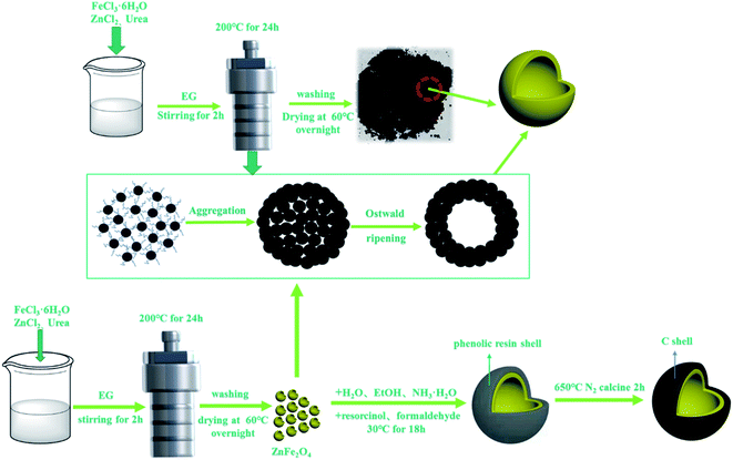 | ||
| Fig. 1 Schematic illustration of the process for the synthesis of hollow core–shell ZnFe2O4@C composites. | ||
3.2 Morphology analysis
The surface morphology and internal microstructure of the as-prepared ZnFe2O4 and ZnFe2O4@C were characterized by SEM and TEM. Fig. 2(a) shows that pure ZnFe2O4 without a C shell is composed of heterogeneous nanospheres with an average size of 300–400 nm. It is noteworthy that some nanospheres in the figure show spherical rupture. Fig. 2(b) is a local magnified view of the fractured spheres. This rupture is most likely due to the impact of CO2 and NH3 gas produced during the formation of the hollow ZnFe2O4 spheres. Fig. 2(c) is a TEM image of ZnFe2O4. It can be seen from the figure that the sample dispersion well, and the spheres have different sizes, with an average size of 300–400 nm, which is following the SEM result. Interestingly, the color around the center of the nanosphere is slightly lighter than the outer ring of the nanospheres, which can be attributed to the formation of hollow ZnFe2O4. Fig. 2(d) is the SEM diagram after the introduction of the C shell. It can be clearly observed that the C shell is uniformly and completely coated on the ZnFe2O4 core, and the corresponding spherical size is also enlarged. Fig. 2(e) is a SEM local amplification of ZnFe2O4@C with core–shell structure. It can be observed from the figure that the C shell has a certain thickness, and this regular core–shell structure provides favorable conditions for the reflection and scattering of electromagnetic waves. Fig. 2(f) is TEM of ZnFe2O4@C, from which it can be observed that the chroma difference of ZnFe2O4 hollow structure is significantly weakened because the addition of C shell makes the size of spherical particles larger, which is not conducive to the observation of the inner cavity, but the hollow structure still exists. In addition, the presence of a C shell around the hollow ZnFe2O4 nanospheres was obviously observed, above all the pictures indicate that we have successfully prepared the hollow core–shell structure ZnFe2O4@C.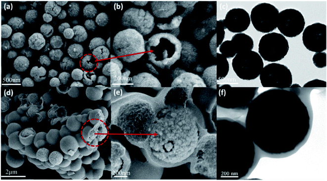 | ||
| Fig. 2 SEM images of ZnFe2O4 (a and b) and ZnFe2O4@C (d and e); TEM images of ZnFe2O4 (c) and ZnFe2O4@C (f). | ||
3.3 Structure analysis
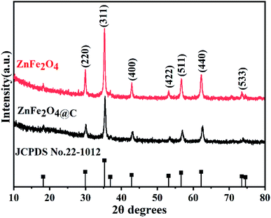
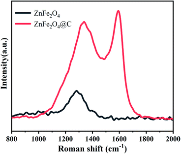
The crystalline structure and phase composition of ZnFe2O4 and ZnFe2O4@C samples were characterized by X-ray diffractometer (XRD). As seen from Fig. 3, it can be observed that apparent diffraction peaks of ZnFe2O4, which are well consistent with the ZnFe2O4 (JCPDS card no. 22-1012),22 the results indicate that ZnFe2O4 with good crystallinity has been successfully prepared. Compared with ZnFe2O4, the position of ZnFe2O4@C of the diffraction peak does not change except only the peak intensity decreases after recombination with the C shell. Another point worth noting is that there are no carbon peaks, which indicates that C exists in an amorphous state.23The degree of graphitization of carbon in ZnFe2O4@C nanocomposite was investigated by Raman spectroscopy, and the result is shown in Fig. 4. There exist two obvious characteristic peaks of D and G bands at around 1350 cm−1 and 1595 cm−1. The peak of the D-band indicates the structural disorders and defects of the C shell,24 while the peak of the G-band reveals the planar vibrations of graphite with lattice structure.25 The intensity ratio of the D-peak to the G-peak (ID/IG) is usually used to describe the degree of disorder of carbon.26 The ID/IG value of ZnFe2O4@C is relatively high (≈0.90), indicating that C shell has a certain degree of graphitization, so there are still many defects within the surface of C shell. The defects can be used as polarization centers to cause polarization relaxation, which contributes to the improvement of electromagnetic wave absorption.27 These results are consistent with the results of XRD patterns and a previous report.28
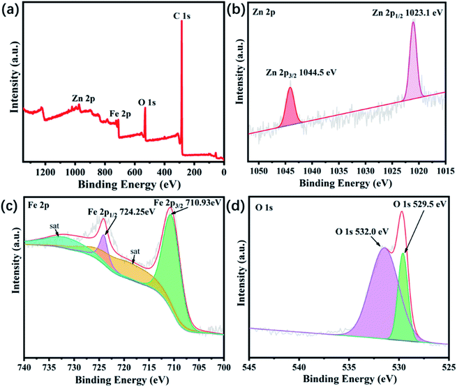
The chemical composition and element valence states of the ZnFe2O4@C are further investigated by XPS. Fig. 5(a) shows the full spectrum of ZnFe2O4@C. Peaks at 284, 530, 721, and 1021 eV corresponded to C 1s, O 1s, Fe 2p, and Zn 2p orbitals, respectively. Fig. 5(b) presents that the Zn 2p spectrum can be deconvoluted into two peaks corresponding to Zn 2p1/2 and 2p3/2 at 1023.1 eV and 1044.5 eV, respectively, indicating that the Zn exists in a bivalent state, which is consistent with the existing form of Zn in spinel structure ZnFe2O4 reported in the previous literature.29 Fig. 5(c) shows four binding energy peaks at 710.9 eV, 718.6 eV, 724.2 eV and 733.6 eV. Interestingly, the two peaks centered at 710.9 eV and 724.2 eV can be ascribed to Fe 2p3/2 and Fe 2p1/2, the other two peaks at 718.6 eV and 733.6 eV are consistent with reconstructed satellite peaks, which suggest Fe element is present as Fe3+ instead of Fe2+ in ZnFe2O4@C composite. In addition, the peak of Fe2+ was not shown, indicating that the prepared sample is pure and free of any impurities. The O 1s spectrum is displayed in Fig. 5(d) and the resolved peaks at 529.5 eV and 532.0 eV, the peak at 529.5 eV represents the lattice oxygen of Fe–O and Zn–O bonds in ZnFe2O4@C and the peak at 532.0 eV corresponds to –OH, H2O and other substances adsorbed on the sample surface. This result, combined with XRD and Raman spectra, indicates that we have successfully prepared ZnFe2O4@C with good purity.
The hollow core–shell structure of the as-obtained ZnFe2O4@C was further investigated by the nitrogen adsorption and desorption test to characterize the specific surface area and pore size type and distribution. As revealed in Fig. 6, the adsorption–desorption isotherms curves all show a typical type IV isotherm, which indicates that all the samples exist in mesoporous structure.30 The surface area of ZnFe2O4 and ZnFe2O4@C is 45.05 m2 g−1 and 69.87 m2 g−1, which may be attributed to the introduction of dielectric C shell not only reducing the lightweight of the composite but also increasing the interfacial area. The illustrations of Fig. 6(a) and (b) show the pore size distribution of ZnFe2O4 and ZnFe2O4@C, respectively. The pore size distribution of ZnFe2O4 is relatively uneven, mainly distributed in 3–40 nm. The large pore size distribution may be due to the fracture of some ZnFe2O4 hollow structures. After the introduction of dielectric C shell, the pore size distribution is mainly distributed in 3–5 nm, and its pore size is significantly smaller, which may be because C shell is a complete and uniform coating on ZnFe2O4 core, filling the holes generated by the rupture of hollow ZnFe2O4. The large specific surface area and the presence of mesoporous pores are beneficial to the generation of interfacial polarization and the multiple reflection and refraction of electromagnetic waves.31,32 Meanwhile, the ZnFe2O4@C of hollow core–shell structure is beneficial to the reduction of the density of the material, which provides favorable conditions for ZnFe2O4@C to become a lightweight microwave absorbing material.
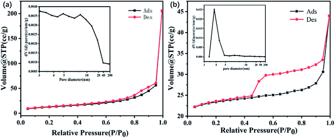 | ||
| Fig. 6 Nitrogen adsorption–desorption isotherm and pore size distribution curves of ZnFe2O4 (a) and ZnFe2O4@C (b). | ||
3.4 Magnetic properties
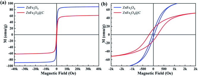
The hysteresis loops of ZnFe2O4 and ZnFe2O4@C were measured by VSM at room temperature with a magnetic field between −40k and +40k Oe.As shown in Fig. 7, all samples reach saturation at the magnetic field less than 10 kOe, which identify samples show typical soft magnetic properties, and the saturation magnetization (Ms) value of the ZnFe2O4 and ZnFe2O4@C was presented to be 89.25 emu g−1 and 61.82 emu g−1, the remanent magnetization (Mr) were 6.39 emu g−1 and 14.19 emu g−1, the coercivity was 50.17 Oe and 200.01 Oe, respectively. It's obvious that the Ms value of ZnFe2O4@C is evidently lower than the pure ZnFe2O4, which is caused by the dielectric C shell. The introduction of a dielectric C shell is beneficial to enhance the dielectric loss of the composite, which is conducive to the good impedance matching between dielectric loss and magnetic loss.33
3.5 Microwave absorption properties
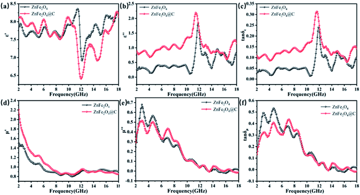
The prepared core–shell structure is composed of ZnFe2O4 with magnetic loss and a C shell with dielectric loss. The complex dielectric constant (ε = ε′ − jε′′) and complex permeability (μ = μ′ − jμ′′) of the core–shell structure ZnFe2O4@C are further studied at 2–18 GHz to investigate the microwave absorbing mechanism of the composite material by the vector network analyzer. The real and imaginary parts of the complex permittivity represent the storage and attenuation capacity of the sample to the electric energy, and the real and imaginary parts of the complex permeability represent the storage and loss capacity of the sample to the magnetic energy, respectively.34 From Fig. 8(a), it can be vividly seen that the ε′ values of ZnFe2O4 and ZnFe2O4@C present a roughly similar trend. Compared with ZnFe2O4@C, the real part of complex permittivity are higher than ZnFe2O4 at 2.0–10.2 GHz, the value varies from 7.5 to 8.5. With increasing frequency from 10.2 to 18.0 GHz, the real part of complex permittivity possesses a reverse trend. The imaginary part of the complex permittivity value of the ZnFe2O4 is lower than ZnFe2O4@C in the whole frequency, that's because the nonmagnetic C shell reduces the magnetism of ZnFe2O4@C. Meanwhile, the ε′′ value curves of ZnFe2O4 and ZnFe2O4@C present a peak around 11.7 GHz, which can be accounted for the interfacial polarization of ZnFe2O4/air, ZnFe2O4/paraffin, ZnFe2O4/C, C/air. Besides, dielectric loss tangent (tan![[thin space (1/6-em)]](https://www.rsc.org/images/entities/char_2009.gif) δε = ε′′/ε′) are utilized to elucidate the dielectric dissipation performance of the microwave absorbers. It is evidently observed that the tan
δε = ε′′/ε′) are utilized to elucidate the dielectric dissipation performance of the microwave absorbers. It is evidently observed that the tan![[thin space (1/6-em)]](https://www.rsc.org/images/entities/char_2009.gif) δε of ZnFe2O4/C is higher than the ZnFe2O4 during the whole frequency range, which shows ZnFe2O4@C own much excellent dielectric loss property. μ′ value of ZnFe2O4 and ZnFe2O4@C are display a monotonically decreasing trend, which decreases from 1.5 at 2.0 GHz to 0.9 at 18 GHz and 2.2 at 2.0 GHz to 0.8 at 18 GHz respectively. It's notable that the phenomenon is typical frequency dispersion behavior and is usually found in carbon-based microwave absorption material.35 As shown in Fig. 8(e), the μ′′ value presents a decreasing trend with moderate fluctuations, the value ranging from 0.68 to 0.05 and 0.5 to −0.02, respectively. The existence of the negative value of μ′′ was interpreted to the partial eddy current loss caused by the movement of charge between C shell and ZnFe2O4. As seen in Fig. 8(f), the curves of tan
δε of ZnFe2O4/C is higher than the ZnFe2O4 during the whole frequency range, which shows ZnFe2O4@C own much excellent dielectric loss property. μ′ value of ZnFe2O4 and ZnFe2O4@C are display a monotonically decreasing trend, which decreases from 1.5 at 2.0 GHz to 0.9 at 18 GHz and 2.2 at 2.0 GHz to 0.8 at 18 GHz respectively. It's notable that the phenomenon is typical frequency dispersion behavior and is usually found in carbon-based microwave absorption material.35 As shown in Fig. 8(e), the μ′′ value presents a decreasing trend with moderate fluctuations, the value ranging from 0.68 to 0.05 and 0.5 to −0.02, respectively. The existence of the negative value of μ′′ was interpreted to the partial eddy current loss caused by the movement of charge between C shell and ZnFe2O4. As seen in Fig. 8(f), the curves of tan![[thin space (1/6-em)]](https://www.rsc.org/images/entities/char_2009.gif) δμ of ZnFe2O4 and ZnFe2O4@C have highly similar changing trends, which certify there is no evident difference about the magnetic loss mechanisms. It's notable that, the value of tan
δμ of ZnFe2O4 and ZnFe2O4@C have highly similar changing trends, which certify there is no evident difference about the magnetic loss mechanisms. It's notable that, the value of tan![[thin space (1/6-em)]](https://www.rsc.org/images/entities/char_2009.gif) δε and tan
δε and tan![[thin space (1/6-em)]](https://www.rsc.org/images/entities/char_2009.gif) δμ of ZnFe2O4, ZnFe2O4/C are close to each other, indicating that EM microwave absorption capability of ZnFe2O4, ZnFe2O4/C is the result of the synergistic effect of magnetic loss and dielectric loss.
δμ of ZnFe2O4, ZnFe2O4/C are close to each other, indicating that EM microwave absorption capability of ZnFe2O4, ZnFe2O4/C is the result of the synergistic effect of magnetic loss and dielectric loss.
To further evaluate the microwave absorption performance of ZnFe2O4 and ZnFe2O4@C, the reflection loss (RL) values are calculated by a vector network analyzer (VNA). In general, an RL value of less than −10 dB means that the microwave absorbing material can absorb 90% of the electromagnetic wave. Therefore, a material with an RL value of less than −10 dB is considered a suitable electromagnetic wave absorbing material. According to the transmission line theory, the RLmax of the sample was calculated and analyzed by the following formula:
 | (1) |
The reflection loss of ZnFe2O4 and ZnFe2O4@C are calculated and analyzed according to the formula (1). As depicted in Fig. 9, the RLmax of ZnFe2O4 reach −32.95 dB with the bandwidth of 2.24 GHz (4.08–6.32 GHz) and ZnFe2O4@C reach −50.97 dB with the bandwidth of 3.2 GHz (6.16–9.36 GHz), meanwhile, it can be seen from the 2D projection curve that the projected area of ZnFe2O4@C is always larger than single ZnFe2O4, no matter the reflection loss is less than −10 dB or −20 dB. Compared with a single ZnFe2O4, the optimal microwave absorbing performance of ZnFe2O4@C is significantly increased, and the coating thickness of the sample decreases from 5.0 mm to 3.5 mm at the optimal reflection loss, which will be beneficial to the sample being widely used as a lightweight microwave absorbing material. Furthermore, the reflection loss of both samples moves to the low frequency with the increased coating thickness, which can be explained by the λ/4 matching model.36
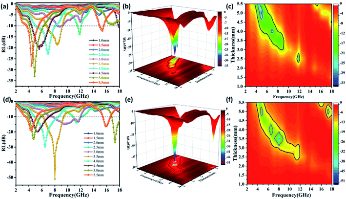 | ||
| Fig. 9 Reflection loss curves of (a) ZnFe2O4, (d) ZnFe2O4@C, 3D RL curves of (b) ZnFe2O4, (e) ZnFe2O4@C, 2D projection curves of (c) ZnFe2O4, (f) ZnFe2O4@C. | ||
The impedance matching (Z) refers to the degree of matching between the free space and the material, attenuation constant (α) is comprehensive electromagnetic wave attenuation ability capability, both of them are also two important factors to evaluate the microwave absorbing performance, which can be described as follows:
 | (2) |
 | (3) |
It can be vividly seen from Fig. 10, the attenuation constant α is not gradually increasing with the increasing frequency, which may be due to the microwave absorbing material's owning different attenuation properties in different bands. It should be noticed that ZnFe2O4@C have a higher value than ZnFe2O4 during the frequency range of 2.0–18 GHz, indicating ZnFe2O4@C has more excellent electromagnetic wave attenuation performance, which has the largest α value is 110.52. Theoretically, the greater the value of α, the better the attenuation performance of the sample to the electromagnetic wave, but in fact, it is not so. Based on this, we further analyzed the relationship between the optimal reflection loss, impedance matching, Z, and attenuation coefficient α, as shown in Fig. 10.
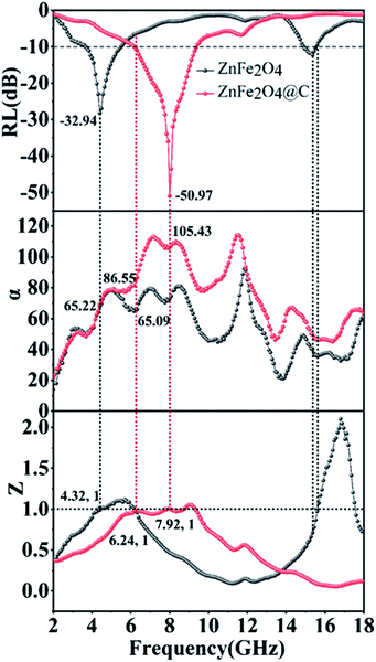 | ||
| Fig. 10 The frequency dependence of RL values, attenuation constant (α) and impedance matching value (Z). | ||
Generally speaking, the closer Z value is to 1, the better impedance matching degree is, and the more electromagnetic waves can enter the material without being reflected off, which is conducive to the loss of electromagnetic waves in the material. We single select α, Z, RL curves of ZnFe2O4, Z value of ZnFe2O4 is equal to 1 at 4.32 GHz and 6.24 GHz at low frequency, and the corresponding attenuation coefficient α value is 65.22 and 65.09, respectively. It is easy to conclude that when the Z value is 1, a larger α value has a larger reflection loss value. This phenomenon is not so regular in the high-frequency region, which indicates that the best reflection loss of the sample may be dominated by the attenuation coefficient α or the impedance matching Z value, or they determine the best reflection loss of the sample together. Similarly, the curves of ZnFe2O4@C present the phenomenon, Z value is equal to 1 at 6.24 GHz and 7.92 GHz, and α value is 86.55 and 105.43. It's apparent that the RL corresponding to different α values is −10.58 dB and −50.97 dB, respectively. This result further proves that excellent microwave absorbing performance is the synergistic effect of attenuation coefficient α and impedance matching Z value.
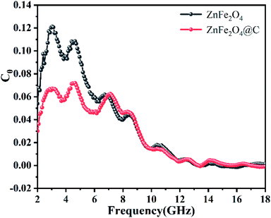
The magnetic loss mechanism of microwave absorbing materials mainly includes natural resonance, exchange resonance, domain wall resonance, and eddy current loss.37 However, domain wall resonance occurs mainly in the MHz range and is generally not considered. In the 2–18 GHz range, natural resonances generally occur at low frequencies and exchange resonances at high frequencies. The generation of eddy current effect is generally evaluated by the value of C0, the equation is as formula (4), when the value of C0 approaches a certain constant, eddy current losses play a major role. As shown in Fig. 11, when in the frequency range of 2–12 GHz, the C0 values of ZnFe2O4 and ZnFe2O4@C vary greatly, which are the result of natural resonance. While, in the frequency range of 12–18 GHz, the C0 value of ZnFe2O4 and ZnFe2O4@C fluctuate very small and tend to be constant, indicating that this frequency range is mainly determined by eddy current losses.
 | (4) |
In order to investigate the electromagnetic wave loss mechanism, Fig. 12 shows the process of absorption and attenuation of electromagnetic waves. First of all, good impedance matching is very important for microwave absorbing performance. The magnetic properties of ZnFe2O4 and dielectric properties of C ensure the good impedance matching of ZnFe2O4@C material. The excellent impedance matching characteristics make the electromagnetic wave enter the material as much as possible without being reflected off, which provides a good condition for the loss of electromagnetic waves. Due to the special hollow core–shell structure of ZnFe2O4@C, the electromagnetic wave entering the material can be reflected and scattered many times in the internal cavity, and thus be lost and attenuated. Secondly, core–shell structure exists a lot of interfacial areas lead to the charge accumulation and vibration under the alternating magnetic field, which is beneficial to the more excellent interfacial polarization. Thirdly, the formation of C shell during the calcination process will produce a large number of defects, which also promote the formation of dipoles, conducive to the generation of dipole polarization, meanwhile, C shell exists in the form of conductive grid, which can be used as electron transmission channel to improve the conductivity of nanocomposites and facilitate the accumulation of charge at the interface, which is also facilitate to the generation of dipole polarization. Last but not least, ZnFe2O4 is the magnetic component of ZnFe2O4@C material, its unique magnetism makes ZnFe2O4@C produce natural resonance at low frequency and eddy current loss at high frequency, which also increases the ability to lose electromagnetic waves.
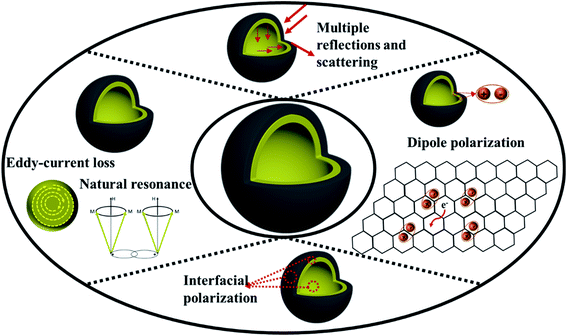 | ||
| Fig. 12 Schematic illustration of the microwave absorption mechanism of hollow core–shell ZnFe2O4@C composite. | ||
4. Conclusion
In this paper, a novel hollow core–shell ZnFe2O4@C microwave absorber had been successfully synthesized by in situ oxidation polymerization method. It was observed that introducing a dielectric C shell exerted an important influence on the microwave absorbing performance. The data indicated that the excellent reflection loss of the hollow core–shell ZnFe2O4@C composites reached −50.97 dB at 8.0 GHz with a thickness of 3.5 mm and the microwave absorption bandwidth with the reflection loss under −10 dB was 3.2 GHz (6.16–9.36 GHz). It was concluded that the special hollow core–shell structure formed by introducing C shell and the microwave absorbing performance was obviously improved. This apparent improvement in microwave absorbing performance can be attributed to the special hollow core–shell structure and the synergistic effect of magnetic ZnFe2O4 with dielectric C shell, which played a vital role in the attenuation of electromagnetic waves. The preparation of ZnFe2O4@C with a special hollow core–shell structure provided a feasible idea for the preparation of lightweight and efficient microwave absorbing materials, which are expected to become a new type of microwave absorbing materials.Funding
The research was funded by Shanghai Natural Science Foundation (21ZR1426200) and National Natural Science Foundation of China (51703123).Ethical statement
This article has been approved by the institutional committee of Shanghai University of Engineering Science. All procedures performed in studies involving humans were in accordance with the ethical standards of the institution or practice at which the studies were conducted.Consent to participate
All authors have agreed on the participation of submission.Conflicts of interest
All authors certify that there is no conflict of interest in this study.Acknowledgements
Appreciate the laboratory and equipment provided by Shanghai University of Engineering Science, and constructive suggestions from Dr Liming Wang, as well as Dr Lihui Xu, Dr Hong Pan, Mr Liuqi Cao, and Mrs Kouqin Chen's help and suggestions for this article.References
- J. Liu, H. Zhang and R. Sun, et al. Hydrophobic, flexible, and lightweight mxene foams for high-performance electromagnetic-interference shielding, Adv. Mater., 2017, 29(38), 1702367 CrossRef PubMed
.
- X. Xie, B. Wang and Y. Wang, et al. Spinel structured MFe2O4 (M = Fe, Co, Ni, Mn, Zn) and their composites for microwave absorption: A review, Chem. Eng. J., 2022, 428, 131160 CrossRef CAS
.
- D. Zhi, T. Li and J. Li, et al. A review of three-dimensional graphene-based aerogels: Synthesis, structure and application for microwave absorption, Composites, Part B, 2021, 211, 108642 CrossRef CAS
.
- V. Sapna, N. Budhiraja and V. Kumar, et al. Shape-controlled synthesis of superparamagnetic ZnFe2O4 hierarchical structures and their comparative structural, optical and magnetic properties, Ceram. Int., 2019, 45(1), 1067–1076 CrossRef
.
- Z. Yang, Y. Wan and G. Xiong, et al. Facile synthesis of ZnFe2O4/reduced graphene oxide nanohybrids for enhanced microwave absorption properties, Mater. Res. Bull., 2015, 61, 292–297 CrossRef CAS
.
- Y. Wang, X. Gao and X. Wu, et al. Hierarchical ZnFe2O4@RGO@CuS composite: Strong absorption and wide-frequency absorption properties, Ceram. Int., 2018, 44(8), 9816–9822 CrossRef CAS
.
- G. Wu, H. Zhang and X. Luo, et al. Investigation and optimization of Fe/ZnFe2O4 as a wide-band electromagnetic absorber, J. Colloid Interface Sci., 2019, 536, 548–555 CrossRef CAS PubMed
.
- X. Huang, Y. Qin and Y. Ma, et al. Preparation and electromagnetic properties of nanosized ZnFe2O4 with various shapes, Ceram. Int., 2019, 45(15), 18389–18397 CrossRef CAS
.
- Y. Ge, Z. Wang and M. Yi, et al. Fabrication and magnetic transformation from paramagnetic to ferrimagnetic of ZnFe2O4 hollow spheres, Trans. Nonferrous Met. Soc. China, 2019, 29(7), 1503–1509 CrossRef CAS
.
- B. Dai, J. Li and W. Wang, et al. Carbon fibers with eddy current loss characteristics exhibit different microwave absorption properties in different graphitization states, Mater. Lett., 2020, 281, 128667 CrossRef CAS
.
- F. Sultanov, C. Daulbayev and B. Bakbolat, et al. Advances of 3D graphene and its composites in the field of microwave absorption, Adv. Colloid Interface Sci., 2020, 285, 102281 CrossRef CAS PubMed
.
- C. Zhou, S. Geng and X. Xu, et al. Lightweight hollow carbon nanospheres with tunable sizes towards enhancement in microwave absorption, Carbon, 2016, 108, 234–241 CrossRef CAS
.
- Y. Wang, W. Sun and K. Dai, et al. Flexible and heat-resistant carbon nanotube/graphene/polyimide foam for broadband microwave absorption, Compos. Sci. Technol., 2021, 212, 108848 CrossRef CAS
.
- Y. Wang, W. Zhou and G. Zeng, et al. Rational design of multi-shell hollow carbon submicrospheres for high-performance microwave absorbers, Carbon, 2021, 175, 233–242 CrossRef CAS
.
- X. Deng, S. Gao and J. Yan, et al. The green synthesis and enhanced microwave absorption performance of core–shell structured multicomponent alloy/carbon nanocomposites derived from the metal-sericin complexation, J. Alloys Compd., 2021, 882, 160680 CrossRef CAS
.
- Y. Gu, P. Dai and W. Zhang, et al. Fe3O4 nanoparticles anchored on hierarchical porous carbon derived from egg white for efficient microwave absorption performance, Mater. Lett., 2021, 304, 130624 CrossRef CAS
.
- W. Ma, P. He and T. Wang, et al. Microwave absorption of carbonization temperature-dependent uniform yolk–shell H-Fe3O4@C microspheres, Chem. Eng. J., 2021, 420(1), 129875 CrossRef CAS
.
- J. Tao, J. Zhou and Z. Yao, et al. Multi-shell hollow porous carbon nanoparticles with excellent microwave absorption properties, Carbon, 2021, 172, 542–555 CrossRef CAS
.
- H. Jia, H. Xing and X. Ji, et al. Self-template and in situ polymerization strategy to lightweight hollow MnO2@polyaniline core–shell heterojunction with excellent microwave absorption properties, Appl. Surf. Sci., 2021, 537, 147857 CrossRef CAS
.
- X. Zhao, Y. Huang and X. Liu, et al. Core–shell CoFe2O4@C nanoparticles coupled with rGO for strong wideband microwave absorption, J. Colloid Interface Sci., 2022, 607(1), 192–202 CrossRef CAS PubMed
.
- B. Wang, H. Chen and S. Wang, et al. Construction of core–shell structured Co7Fe3@C nanocapsules with strong wideband microwave absorption at ultra-thin thickness, Carbon, 2021, 184, 223–231 CrossRef CAS
.
- F. Li, W. Zhan and L. Zhuang, et al. Acquirement of strong microwave absorption of Znfe2O4@SiO2@reduced graphene oxide/pvdf composite membranes by regulating crystallization behavior, J. Phys. Chem. C, 2020, 124(27), 14861–14872 CrossRef CAS
.
- B. Han, W. Chu and X. Han, et al. Dual functions of glucose induced composition-controllable Co/C microspheres as high-performance microwave absorbing materials, Carbon, 2020, 168, 404–414 CrossRef CAS
.
- R. Shu, Y. Wu and W. Li, et al. Fabrication of ferroferric oxide–carbon/reduced graphene oxide nanocomposites derived from Fe-based metal–organic frameworks for microwave absorption, Compos. Sci. Technol., 2020, 196, 108240 CrossRef CAS
.
- A. C. Ferrari, S. E. Rodil and J. Robertson, Interpretation of infrared and Raman spectra of amorphous carbon nitrides, Phys. Rev. B: Condens. Matter Mater. Phys., 2003, 67(15), 1553061–15530620 CrossRef
.
- D. Liu, R. Qiang and Y. Du, et al. Prussian blue analogues derived magnetic FeCo alloy/carbon composites with tunable chemical composition and enhanced microwave absorption, J. Colloid Interface Sci., 2018, 514, 10–20 CrossRef CAS PubMed
.
- Z. Sun, Z. Yan and K. Yue, et al. Multi-scale structural nitrogen-doped rGO@CNTs composites with ultra-low loading towards microwave absorption, Appl. Surf. Sci., 2021, 538, 147943 CrossRef CAS
.
- E. Yang, X. Qi and R. Xie, et al. Core@shell@shell structured carbon-based magnetic ternary nanohybrids: Synthesis and their enhanced microwave absorption properties, Appl. Surf. Sci., 2018, 441, 780–790 CrossRef CAS
.
- H. Li, Y. Hou and L. Li, Tunable design of yolk–shell ZnFe2O4@C composites for enhancing electromagnetic wave absorption, Powder Technol., 2021, 378, 216–226 CrossRef CAS
.
- Y. Du, T. Liu and B. Yu, et al. The electromagnetic properties and microwave absorption of mesoporous carbon, Mater. Chem. Phys., 2012, 135(2), 884–891 CrossRef CAS
.
- W. Bo, C. Zhou and Z. Yao, et al. Encapsulation of high specific surface area red blood cell-like mesoporous carbon spheres by magnetic nanoparticles: A new strategy to realize multiple electromagnetic wave loss mechanism, Carbon, 2021, 184, 232–244 CrossRef
.
- Y. Cheng, Z. Li and Y. Li, et al. Rationally regulating complex dielectric parameters of mesoporous carbon hollow spheres to carry out efficient microwave absorption, Carbon, 2018, 127, 643–652 CrossRef CAS
.
- D. Zhang, Y. Xiong and J. Cheng, et al. Synergetic dielectric loss and magnetic loss towards superior microwave absorption through hybridization of few-layer WS2 nanosheets with NiO nanoparticles, Sci. Bull., 2020, 65(2), 138–146 CrossRef CAS
.
- R. Deng, B. Chen and H. Li, et al. MXene/Co3O4 composite material: Stable synthesis and its enhanced broadband microwave absorption, Appl. Surf. Sci., 2019, 488, 921–930 CrossRef CAS
.
- S. Wang, H. Ren and W. Lian, et al. Dispersed spherical shell-shaped palygorskite/carbon/polyaniline composites with advanced microwave absorption performances, Powder Technol., 2021, 387, 277–286 CrossRef CAS
.
- R. Shu, G. Zhang and X. Wang, et al. Fabrication of 3D net-like MWCNTs/ZnFe2O4 hybrid composites as high-performance electromagnetic wave absorbers, Chem. Eng. J., 2018, 337, 242–255 CrossRef CAS
.
- Z. Liao, M. Ma and Z. Tong, et al. Fabrication of ZnFe2O4/C@PPy composites with efficient electromagnetic wave absorption properties, J. Colloid Interface Sci., 2021, 602, 602–611 CrossRef CAS PubMed
.
| This journal is © The Royal Society of Chemistry 2022 |

