DOI:
10.1039/D2RA04005K
(Paper)
RSC Adv., 2022,
12, 22662-22670
Decreasing free fatty acid of crude palm oil with polyvinylidene fluoride hollow fiber membranes using a combination of chitosan and glutaraldehyde
Received
29th June 2022
, Accepted 29th July 2022
First published on 12th August 2022
Abstract
Crude palm oil (CPO) has emerged as a significant commodity in the economic and social development of producer nations. However, the presence of free fatty acids (FFAs) results in decreased CPO quality. Due to many advantages, the PVDF hollow fiber membrane has a higher potential to remove FFA from CPO than other polymeric membranes, despite the fact that FFA rejection performance remains poor. To solve this issue, membrane surface modification has emerged as one of the potential options for increasing electrostatic contact between the membrane surface and the FFA, resulting in high efficiency FFA separation from CPO. In this investigation, the membrane surface was coated with chitosan (CS) as a coating agent and glutaraldehyde (GA) as a crosslinking agent. The findings of the characterization demonstrated that the presence of a CS/GA combination with a low CS weight on the membrane surface resulted in enhanced hydrophilicity, porosity, water flow, and surface roughness. Furthermore, as compared to the uncoated PVDF hollow fiber membrane, the performance of the CPO with PVDF/CS 0.5 hollow fiber membrane achieved a maximum result of FFA rejection of up to 14.99%. The use of a mixture of CS and GA on the PVDF membrane surface to improve FFA reduction has been shown to be a promising technique for scaling up membrane technology.
Introduction
Currently, the palm oil industry has an important role in the social and economic growth of nations such as Indonesia, Malaysia, Thailand, Colombia, and Nigeria.1,2 Due to its low price, palm oil has become the most consumed vegetable oil in the world over the past years.3,4 Crude palm oil (CPO) can be refined from the mesocarp of the palm fruit and includes various components that have numerous benefits for human health, such as triacyl-glycerol or neutral lipids, vitamin E (tocopherol and tocotrienol), vitamin A (carotenoid), and phytosterol.5,6 However, the presence of free fatty acids (FFAs) in CPO reduces its quality, resulting in significant oil loss and unwanted saponification.2,6 Therefore, the level of FFA in CPO must be reduced through the deacidification process.
The deacidification process can be achieved by conventional refineries through physical or chemical processes. Conventional refineries had a substantial reduction in FFA, reduced costs, and fewer by-products.1 Meanwhile, conventional refineries are unfavorable because of high energy and additional chemical requirements, as well as the production of hazardous waste, nutritional loss, and unfavorable oil.7–9 As a result, an alternative refining method must be used to get high FFA separation efficiency and performance from CPO.
Membrane technology has received great attention as an advanced physical process in numerous oil separations, especially FFA separation from CPO.10–14 The simplicity of the processing processes, operation at ambient temperature, low energy consumption, and low-cost operation were all demonstrated by membrane technology.2,8,15 The performance of the progress of membrane technology is contingent upon the selection of materials that can contribute to the deacidification performance process. In addition, organic polymers have recently emerged as a significant material in membrane construction, outpacing inorganic materials (such as ceramics, carbons, and zeolites) in the present market.16
Several attempts were made to use polymeric membranes for the deacidification process. Research by Aryanti et al. revealed that flat sheet ultrafiltration membrane, using polyethersulfone (PES), has been fabricated successfully for the degumming process of CPO with 99% rejection of phospholipids, but could not separate FFA effectively because of the smaller molecular size of FFA (0.372 nm for palmitic acid and 2 nm for oleic acid), thus that FFA could enter and pass through the membrane pore.17 PVDF was selected over other polymers for ultrafiltration (UF) membranes material owing to its high chemical resistance and mechanical qualities.18 Within the operational circumstances (2–6 bar, 40 °C, 300 rpm stirring speed), the PVDF membrane demonstrated up to 95% phospholipid retention.19 Additionally, PVDF based UF membrane potentially separated FFA from soybean oil with hydrophobic properties, although the percent of FFA rejection was still lower, at 6.3%.2,20–23 Hence, the performance of the polymeric membrane needs to be improved.
Membrane surface modification has emerged as one of the promising techniques with great selectivity toward FFA for improving membrane performance with higher FFA rejection. Because FFA is a carboxyl derivative molecule, the membrane surface involving intermolecular interaction with FFA was expected to contribute significantly to FFA rejection. The PVDF membrane surface can be coated with chitosan (CS), poly[-(1,4)-2-amino-2-deoxy-D-glucose], which has an amine group that can interacts electrostatically with FFA as illustrated in Fig. 1. Additionally, the CS-coated membrane could improve antifouling performance.22,24–26 However, CS has high swelling properties in water that cause difficulty in standing on the membrane surface during the infiltration process at high pressure.24 To address this, CS was combined with glutaraldehyde (GA) to utilize the crosslinking mechanism depicted in Fig. 2, which could improve its water resistance, acid resistance, and surface properties.24,27 Zhao et al. demonstrated that the addition of GA crosslinker caused the CS barrier layer to become denser and decrease water swelling property which might enhance BSA rejection ratio (%) from 19.2 to 33.4%.24
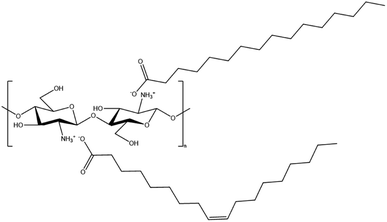 |
| | Fig. 1 Electrostatic interaction between CS and FFA (as palmitic acid and oleic acid). | |
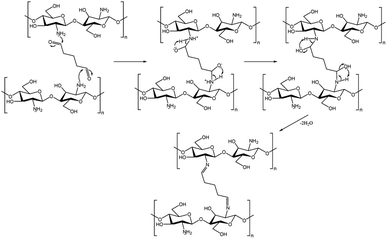 |
| | Fig. 2 Crosslinking reaction mechanism between CS and GA via Schiff base functionalization. | |
In this research, PVDF membranes were produced in hollow fiber form through a dry–wet jet spinning method, resulting in a hollow fiber membrane with a high active surface area per volume that was suitable for practical membrane applications.28 After that, the surface of the PVDF membrane was modified with a CS/GA mixture containing different CS weights. This study aims to improve membrane performance in deacidification process of CPO without solvent dilution by determining surface roughness, functional group, porosity, water flux, solute rejection, oil flux, and FFA rejection.
Experimental
Materials
Chemicals used in this research were polyvinylidene fluoride (PVDF, Kynar®740, 99%, Arkema Inc. Philadelphia), N-methyl-2-pyrrolidone (NMP, 99%, Across Chemicals), ethylene glycol (EG, 99%, Across Chemicals), chitosan (molecular weight (Mw) = 50![[thin space (1/6-em)]](https://www.rsc.org/images/entities/char_2009.gif) 000 Da, 85% diacylation), glutaraldehyde (GA, Grade II, 25%), crude palm oil (CPO, Sime Darby Bhd. Malaysia), acetic acid (99%, Sigma Aldrich), water, epoxy (resin and hardener), ethanol (≥98.5%, Sigma Aldrich), sodium hydroxide (NaOH, ≥98%, Merck), polyethylene glycol (PEG, Mw = 3400 Da, >99%), and bovine serum albumin (BSA, Mw = 45
000 Da, 85% diacylation), glutaraldehyde (GA, Grade II, 25%), crude palm oil (CPO, Sime Darby Bhd. Malaysia), acetic acid (99%, Sigma Aldrich), water, epoxy (resin and hardener), ethanol (≥98.5%, Sigma Aldrich), sodium hydroxide (NaOH, ≥98%, Merck), polyethylene glycol (PEG, Mw = 3400 Da, >99%), and bovine serum albumin (BSA, Mw = 45![[thin space (1/6-em)]](https://www.rsc.org/images/entities/char_2009.gif) 000 Da, ≥98%, Sigma Aldrich).
000 Da, ≥98%, Sigma Aldrich).
Procedure
Fabrication of PVDF hollow fiber membranes. The dry–wet jet spinning was used as a method for fabricating hollow fiber membranes.2,29,30 After that, the dope solution was processed with the ultrasonication method and rested in the oven at 50 °C for 24 hours to reduce bubbles in the dope solution. Next, the dope solution was fabricated into hollow fiber form using the dry–wet jet spinning method as in Fig. 3. Water was used in the coagulation bath with the temperature set at 300 K and the parameters of the spinning process were summarized in Table 1. After the spinning process, the PVDF hollow membrane was immersed in a water bath at room temperature for 24 hours and post-treated with ethanol aqueous solution (50 wt%). Finally, the hollow fiber membrane was dried at room temperature.
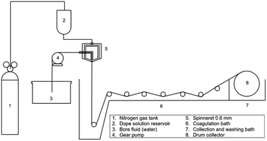 |
| | Fig. 3 Schematic of hollow fiber spinning for fabrication of PVDF hollow fiber membranes. | |
Table 1 Spinning process condition for fabrication of PVDF hollow fiber membranes
| Parameters |
Value |
| Inner/outer diameter in spinneret |
1.15 mm/0.55 mm |
| Flow rate of dope solution |
7.2 mL min−1 |
| Bore fluid flow rate |
2.2 mL min−1 |
| Temperature of bore fluid |
300 K |
| Air gap distance |
10 cm |
| Rate of drum wind-up |
18.3 cm s−1 |
Surface modification of PVDF hollow fiber membranes. The PVDF hollow fiber membranes were coated with CS/GA as in the procedure from Silitonga et al.30 The CS/GA solution was prepared by dissolving CS in 40 mL acetic acid 2% and stirred until homogenous with the variation of CS addition set to 0.1, 0.2, 0.3, 0.4, and 0.5 g. Then, about 5 mL of GA was added to CS solution so that the concentration of GA in solution reached approximately 10% w/w which has been reported as the effective concentration to crosslink chitosan solution.31 Next, hollow fiber membranes were immersed in CS/GA solution for 30 minutes at room temperature. After that, hollow fiber membranes were heated with following steps: 45 °C for 1 hour, 50 °C for 1 hour, 55 °C for 1 hour, and 60 °C for 2 hours to complete crosslinking reaction. After heating process, hollow fiber membranes were immersed in NaOH/ethanol solution (50% v/v) to neutralize the remaining acetic acid. At last, hollow fiber membranes were rinsed twice with distillate water and dried in an oven at 60 °C for 24 hours. Finally, hollow fiber membranes were labeled as PVDF, PVDF/CS 0.1, PVDF/CS 0.2, PVDF/CS 0.3, PVDF/CS 0.4, and PVDF/CS 0.5.
Characterization of hollow fiber membranes. The surface roughness of hollow fiber membranes was characterized with atomic force microscopy (AFM, Model: N 8 Neos Accurion Halcyonics, Bruker). A piece of sample was cut to the length of 1 cm and placed on a glass object. The contact angle of hollow fiber membranes was measured with a Goniometer (Model: OCA 15 EC, Dataphysics). At least about 10 contact angles were obtained and used to gain the average contact angle. The functional groups of the membrane and the observation of chemical structure differences before and after the crosslinking process were analyzed with a Fourier transform infrared (FTIR) spectroscope (Model: Nicolet5700, Thermo Electron Corporation).To examine the porosity membrane, about 5 strands of hollow fiber with a length of about 5 cm were glued with epoxy (ratio of resin to hardener = 10![[thin space (1/6-em)]](https://www.rsc.org/images/entities/char_2009.gif) :
:![[thin space (1/6-em)]](https://www.rsc.org/images/entities/char_2009.gif) 5) at each end and left for 24 hours until drying. Next, the samples were immersed in water for 6 hours at room temperature and then weighed. Then, samples were dried in a vacuum oven at 40 °C for 6 hours and weighted. The porosity of the hollow fiber membrane was calculated with eqn (1):32,33
5) at each end and left for 24 hours until drying. Next, the samples were immersed in water for 6 hours at room temperature and then weighed. Then, samples were dried in a vacuum oven at 40 °C for 6 hours and weighted. The porosity of the hollow fiber membrane was calculated with eqn (1):32,33
| |
 | (1) |
where:
Wwet = weight of membrane that contained water (kg).
Wdry = weight of dried membrane (kg).
ρwater = density of pure water (∼1 kg L
−1).
Vneat = volume of membrane in wet state (L).
To determine molecular weight cut-off (MWCO) as rejection and water flux, a hollow fiber membrane was prepared as in porosity measurement. After that, samples were installed in a water permeation hollow fiber system. Prior to installation, samples were immersed in water for 15 minutes. About 0.1 g of each BSA and PEG were dissolved in 1 L of distilled water to obtain the feed solution. Then, each feed solution was filtrated through hollow fiber membranes with a pressure set to 2 bars. The concentration of PEG was analyzed using a total organic carbon (TOC) analyzer (Shimadzu Corporation), while the BSA concentration was determined with a spectrophotometer (Model: HACH DR 5000) at a wavelength of 280 nm. The water flux (Jwater) and rejection (R) were calculated with the formulas in eqn (2) and (3):
| |
 | (2) |
| |
 | (3) |
where:
Q = quantity of water permeate (L).
A = cross-sectional area of membranes (m
2).
t = filtration time (h).
Cp = concentration of solute (BSA or PEG) in permeate (ppm).
Cf = concentration of solute (BSA or PEG) in feed (ppm).
In addition, a scanning electron microscope (SEM, TM 3000, Hitachi) was utilized to observe the cross-sectional morphologies of hollow fiber membranes. To characterize the membrane morphology, it was first dried and then immersed in liquid nitrogen for a few seconds until it solidified. The soaking sample is raised and broken at both ends using tweezers. For conduction, these sample pieces are then coated with palladium and platinum.
Lab-scale hollow fiber membrane filtration. As shown in Fig. 4, FFA separation from CPO was performed with a hollow fiber membrane filtration model according to the adopted system by Azmi et al.2 About 1 L of CPO was put into the filtration model at a temperature of 60 °C in a set-in water bath using a multi-purpose immersion coiled heater (Model: 830-S1, Protech Electronic) and pressure was maintained at 2 bar using nitrogen gas so that CPO was coming out of the permeate channel and was collected in beaker glass. The flux and rejection were calculated every 30 minutes to determine the performance of hollow fiber membranes.
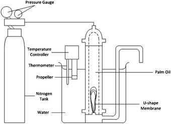 |
| | Fig. 4 Pressure driven dead-end filtration of laboratory-scale hollow fiber membrane for CPO refinery.2 | |
The determination of FFA rejection and oil flux has become important for hollow fiber membrane performance. Measurement of oil flux value was done by weighting permeate that collected in beaker glass, while oil rejection was determined by measuring the concentration of CPO feed and permeate with a turbidimeter. The oil flux (Joil) and rejection (R) were calculated with formulas in eqn (4) and (5):
| |
 | (4) |
| |
 | (5) |
where:
A = cross-sectional area of membranes (m
2).
t = filtration time (h).
Cp = concentration of solute (oil or FFA) in permeate (ppm).
Cf = concentration of solute (oil or FFA) in feed (ppm).
Results and discussion
Hollow fiber membrane topography
The AFM characterization was conducted to analyze the surface roughness of the hollow fiber membrane surface at various CS weights. The results of AFM analysis were shown as a three-dimensional topography image in Fig. 5 and summary data in Table 2 with compared data from the previous study.30 Membrane coating with a CS/GA mixture could modify surface roughness.30 Also, the addition of CS content on surface modification process enhanced the average (Sa) and root mean square roughness (Sq) until the maximum value that was owned by PVDF/CS 0.3, which is 2.41 and 3.35 nm, respectively. However, further increasing of CS weight caused lower value of Sa and Sq, thus the membrane surface became smoother.
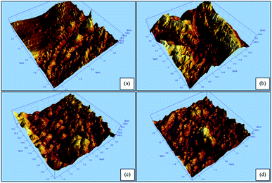 |
| | Fig. 5 AFM image of hollow fiber membranes: (a) PVDF/CS 0.2; (b) PVDF/CS 0.3; (c) PVDF/CS 0.4; and (d) PVDF/CS 0.5. | |
Table 2 Roughness value of hollow fiber membrane
| Parameters |
Surface roughness (nm) |
| Average roughness (Sa) |
Root mean square roughness (Sq) |
| PVDF30 |
0.661 |
0.895 |
| PVDF/CS 0.130 |
0.868 |
1.31 |
| PVDF/CS 0.2 |
1.20 |
1.65 |
| PVDF/CS 0.3 |
2.41 |
3.35 |
| PVDF/CS 0.4 |
2.23 |
3.25 |
| PVDF/CS 0.5 |
1.11 |
1.39 |
Functional group identification on membrane surface
FTIR analysis was used to confirm the existence of functional groups in hollow fiber membrane material. The FTIR characterization result of the hollow fiber membrane is presented in Fig. 6. The bands located at 1395 and 840 cm−1 corresponded to CH2 wagging and C–F stretching vibrations in the PVDF structure.34 The C![[double bond, length as m-dash]](https://www.rsc.org/images/entities/char_e001.gif) O bond in the GA and CS structures was detected at 1645 cm−1.35 Meanwhile, the C
O bond in the GA and CS structures was detected at 1645 cm−1.35 Meanwhile, the C![[double bond, length as m-dash]](https://www.rsc.org/images/entities/char_e001.gif) N bond between CS and GA was identified at 1567 cm−1.35 The peaks in the range of 3500–3000 cm−1 and 3000–2500 cm−1 corresponded to O–H and C–H stretching vibrations, respectively. The appearance of C
N bond between CS and GA was identified at 1567 cm−1.35 The peaks in the range of 3500–3000 cm−1 and 3000–2500 cm−1 corresponded to O–H and C–H stretching vibrations, respectively. The appearance of C![[double bond, length as m-dash]](https://www.rsc.org/images/entities/char_e001.gif) O, C
O, C![[double bond, length as m-dash]](https://www.rsc.org/images/entities/char_e001.gif) N, and O–H bonds in PVDF/CS demonstrated the success of coating CS on the membrane surface.
N, and O–H bonds in PVDF/CS demonstrated the success of coating CS on the membrane surface.
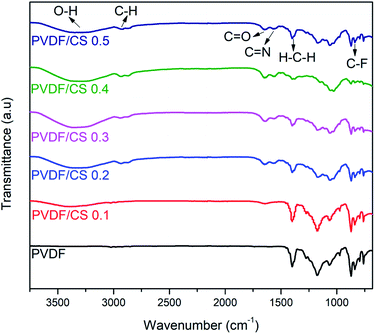 |
| | Fig. 6 Vibrational spectra of hollow fiber membranes. | |
Surface hydrophilicity, porosity, and water flux of membrane
In Fig. 7, the water contact angle, porosity, and pure water flux of the membrane at various CS weights were obtained. The addition of a CS/GA mixture to the membrane surface increased its hydrophilicity, as shown in Fig. 7(a). As a result, the surface modified membrane became stronger at attaching FFA than the uncoated membrane via electrostatic interaction. A similar result was found by Cui et al. who found that the appearance of chitosan on polycaprolactam (PA6) lowered the contact angle from 91.4° (bare PA6) to 34.7°.36 It has been revealed that the hydration capability of hydroxyl and amino groups in the chitosan chain caused the enhancement of the membrane hydrophilicity.25 However, an excess amount of CS caused the surface membrane to be more hydrophobic. Fig. 7(b) also shows the results of membrane porosity and pure water flux measurements. The enhancement of surface hydrophilicity led to higher porosity and pure water flux with CS/GA mixture addition. In contrast, when much more CS is added, there is less porosity and less pure water flow.
 |
| | Fig. 7 Effect of CS addition toward (a) water contact angle; (b) membrane porosity and pure water flux. | |
Hollow fiber membrane morphology observation
The cross-sectional morphologies of the uncoated PVDF membrane, the lowest CS-coated PVDF (0.1) membrane, and the highest CS-coated PVDF (0.5) membrane are observed using SEM (Fig. 8). Due to phase inversion between the coagulation liquid and polymer solution during the dry/wet spinning process, all hollow fiber membranes exhibited finger-like pores.37,38 Coating 0.1 g of CS on a PVDF hollow fiber membrane still preserved the finger-like pore structure. Moreover, the addition of CS results in the formation of larger channels inside the finger-like pore.39 Furthermore, introducing CS to a PVDF membrane could increase its hydrophilicity owing to its high concentration of hydrophilic groups.22,40 Thus, it supports the water flux and porosity result. At 0.1 g CS coating did not block the pore, thus providing higher water flux and porosity. However, increasing the concentration of chitosan and its interaction with PVDF results in a denser structure, which contributes to the higher hydrophobicity of the surface modified membrane.41 In addition, according to Chanachai et al., at a high chitosan coating concentration (2% (w/v)), water flux declined, which attributed to a thicker chitosan layer on the membrane surface, providing a higher barrier to the flow of water.42 Similarly, increasing the CS coating concentration results in denser pores, which contribute significantly to the decrease in porosity, water flow, and hydrophilicity (Fig. 8(c) and (c1)). In addition, the coating CS on the PVDF membrane was observed in Fig. 8(d) and (e). In comparison to the neat membrane, which had an observed pore in surface morphology, the PVDF/CS membrane had a CS layer on the PVDF surface that was successfully covered.
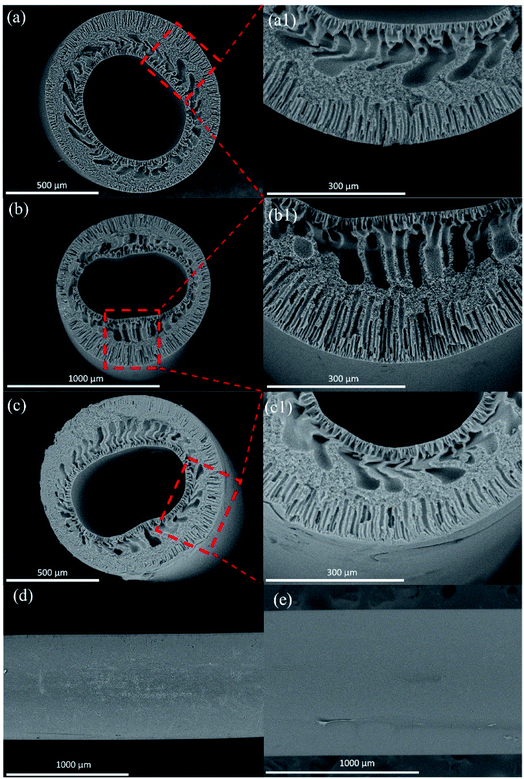 |
| | Fig. 8 SEM image of cross-section (a) and (a1) PVDF, (b) and (b1) PVDF/CS 0.1, (c) and (c1) PVDF/CS 0.5; surface (d) PVDF, and (e) PVDF/CS 0.1. | |
MWCO of membrane
MWCO is defined as the molecular weight of a solute that is 90% rejected. The experiments were carried out with different molecular weight solutes, BSA and PEG. The effect of chitosan addition on solute rejections for PVDF membranes is seen in Table 3. All of the membranes exhibited MWCO greater than 45 kDa, which can be categorized into the ultrafiltration (UF) range.43 In the case of PEG solute, the MWCO of PVDF/CS 0.5 is expected to become the lowest among other membranes due to the larger rejection of PEG. The unique case, interestingly, was found in BSA solute, where the MWCO of PVDF/CS 0.5 is projected to be lower than PVDF/CS 0.1 due to the largest rejection of BSA by PVDF/CS 0.1. Indeed, the membrane filtration process is based on physical separation, which is mostly dependent on the membrane pore size and kinetic diameter of the solute. Interestingly, there is another factor that contributes to the lower rejection of BSA by PVDF/CS 0.5. Since the pore blocking of PVDF/CS 0.5 can be seen clearly according to the SEM image above, a solution-diffusion mechanism is proposed to play the major role in BSA diffusion. As a result, the increased hydrophobicity of the PVDF/CS 0.5 surface promoted BSA adsorption, as indicated by the fact that BSA is mostly adsorbed on the nonpolar surface.44
Table 3 MWCO of PVDF hollow fiber membranes
| Membrane |
Solute rejection (%) |
Solute rejection (%) |
| 3.4 kDa (PEG) |
45 kDa (BSA) |
| PVDF |
7.70 |
38.23 |
| PVDF/CS 0.1 |
8.89 |
82.42 |
| PVDF/CS 0.5 |
13.40 |
63.35 |
Hollow fiber membrane performance
Membranes with different CS weights were examined in terms of oil flux and FFA rejection to observe and prove the membrane's ability to separate FFA from CPO as shown in Fig. 9. At 0.5 h permeation time, the addition of CS amount in the CS/GA mixture slightly increased oil flux, although the value of oil flux is lower than the PVDF membrane. This is due to the hydrophilicity of the membrane surface, which was proven by the water contact angle with the same trend. Therefore, the hydrophilic surface membrane plays an important role in oil permeation. However, oil flux of all membranes has been decreased along with the oil permeation process due to membrane fouling, as a common issue in membrane-based separation applications.2 Similar results have been found in the previous research about membrane surface modification, in which Azmi et al.2 reported the decrease in oil flux after membrane coating with polyvinyl alcohol (PVA)/GA mixture due to membrane fouling. To counter that, a membrane cleaning process is needed to recover the oil flux, and the filtration process can be retained for a longer time. From the result of FFA rejection after 4.5 h permeation, it was found that surface coating with a CS/GA mixture caused improvement in FFA rejection until a maximum value of 14.99% (PVDF/CS 0.5) due to the higher amount of CS/GA binding site toward FFA via electrostatic interaction.26 Furthermore, the maximum value of FFA rejection in this research was higher than the result from Azmi et al.2 report, proving the high superiority of CS material instead of PVA in FFA separation application. However, decreasing FFA rejection of PVDF/CS 0.5 has occurred after 1 h of filtration. It has been suspected that this issue can happen due to the interference with FFA attachment on the membrane surface. This interference was caused by several factors, such as: (1) electrostatic interaction strength between carboxyl groups (–COO−) of FFA and amine groups (–NH3+) of the chitosan layer on the surface modified membrane;22,24–26 and (2) pressure-driven force during the filtration process.45 In addition, overview membranes for FFA removal are exhibited in Table 4. Compared to pure CPO feed from other membranes, PVDF/CS membrane reveals potential for the future development to separate FFA.
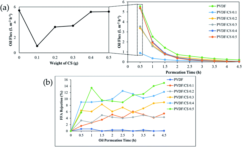 |
| | Fig. 9 Oil flux (a) and FFA rejection (b) of hollow fiber membrane with different CS weight. | |
Table 4 Membrane for FFA removal
| Membrane |
Feed |
FFA rejection (%) |
References |
| PVDF/PVA |
Pure CPO |
5.93 |
R. A. Azmi et al.2 |
| PVDF/AC |
Pure CPO |
6.31 |
N. H. Othman et al.46 |
| PVDF/MagS |
Pure CPO |
8.18 |
N. H. Othman et al.46 |
| PVDF/CaS |
Pure CPO |
7.46 |
N. H. Othman et al.46 |
| Comercial membrane (NF030306) purchased from SOLSEP |
FFA (14.4 g L−1) in acetone |
51.24 |
D. N.·F. A. Ismail et al.47 |
| PVDF/CS 0.5 |
Pure CPO |
14.99 |
This work |
| PSSU |
Pure CPO |
16.54 |
N. H. Othman et al.48 |
| PVDF-CA |
Crude soybean oil–hexane mixture |
58 |
L. R. Firman et al.49 |
| PVDF-PDMS-PC |
Soybean oil/hexane mixture |
27 |
L. Firman et al.50 |
Conclusions
In this research, the viability of chitosan (CS) and glutaraldehyde (GA) as crosslinkers toward modification of PVDF hollow fiber membrane has been studied. The existence of CS/GA on the membrane surface caused increasing surface roughness and pure water flux, but further addition of CS decreased surface roughness. On the other hand, membrane morphology observed by SEM demonstrates a thicker chitosan layer on the membrane surface which is associated with hydrophilicity properties. Experimental results of crude palm oil (CPO) filtration with a hollow fiber membrane exhibited that surface modification by CS/GA mixture led to higher free fatty acid (FFA) rejection but lower oil rejection. The maximum performance of FFA separation from CPO was obtained by PVDF/CS 0.5 (14.99%), which is higher than in previous studies (5.93%). This result of research provided the potential application of the CS/GA mixture as an alternative for membrane surface modification with enhanced properties and performance. Further performing the performance stability under cyclic mode testing (e.g., 5 cycles) of FFA removal in CPO is necessary to be conducted at various solvent concentrations for future investigation.
Conflicts of interest
There are no conflicts to declare.
Acknowledgements
The authors would like to appreciate to Indonesian Ministry of Research and Higher Education for providing Beasiswa Pendidikan Pascasarjana Dalam Negeri (BPPDN) Scholarship for R. S. S. to finish this research in Institut Teknologi Sepuluh Nopember (ITS), Indonesia under collaboration with Advanced Membrane Technology (AMTEC) Research Centre, Universiti Teknologi Malaysia (UTM). In addition, the authors are grateful to the Institut Teknologi Sepuluh Nopember for providing financial support for this work, which was facilitated through the Publication Writing and IPR Incentive Program (PPHKI) project scheme.
Notes and references
- O. I. Mba, M. J. Dumont and M. Ngadi, Food Biosci., 2015, 10, 26–41 CrossRef CAS.
- R. A. Azmi, P. S. Goh, A. F. Ismail, W. J. Lau, B. C. Ng, N. H. Othman, A. M. Noor and M. S. A. Yusoff, J. Food Eng., 2015, 166, 165–173 CrossRef CAS.
- J. Qiu, Y. Feng, X. Zhang, M. Jia and J. Yao, J. Colloid Interface Sci., 2017, 499, 151–158 CrossRef CAS.
- Consumption of vegetable oils worldwide from 2013/14 to 2021/2022, by oil type, https://www.statista.com/statistics/263937/vegetable-oils-global-consumption, (accessed May 2022) Search PubMed.
- F. Razi, U. Fathanah and N. M. Erfiza, J. Rekayasa Kim. Lingkungan, 2019, 14, 89–96 CrossRef.
- N. H. Azeman, N. A. Yusof and A. I. Othman, Asian J. Chem., 2015, 27, 1569–1573 CrossRef CAS.
- S. Arora, S. Manjula, A. G. Gopala Krishna and R. Subramanian, Desalination, 2006, 191, 454–466 CrossRef CAS.
- Z. F. Cui and H. S. Muralidhara, Membrane Technology, Elsevier, Oxford, 1st edn., 2010 Search PubMed.
- S. E. Iyuke, F. R. Ahmadun and R. A. Majid, J. Food Process Eng., 2004, 27, 476–496 CrossRef.
- E. Lv, S. Ding, J. Lu, W. Yi and J. Ding, Int. J. Chem. React. Eng., 2020, 18(9) DOI:10.1515/ijcre-2019-0224.
- I. G. Wenten, K. Khoiruddin, P. T. P. Aryanti, A. V. Victoria and G. Tanukusuma, Rev. Chem. Eng., 2020, 36, 237–263 CrossRef CAS.
- S. Rangaswamy, G. S. Kumar and C. Kuppusamy, Compr. Rev. Food Sci. Food Saf., 2021, 20, 5015–5042 CrossRef CAS.
- Q. Zhong, G. Shi, Q. Sun, P. Mu and J. Li, J. Membr. Sci., 2021, 640, 119836 CrossRef CAS.
- M. Wu, B. Xiang, P. Mu and J. Li, Sep. Purif. Technol., 2022, 297, 121532 CrossRef CAS.
- M. C. Chiu, C. de Morais Coutinho and L. A. G. Gonçalves, Desalination, 2009, 245, 783–786 CrossRef CAS.
- N. F. Himma, S. Anisah, N. Prasetya and I. G. Wenten, J. Polym. Eng., 2016, 36, 329–362 CrossRef.
- N. Aryanti, D. H. Wardhani and A. Nafiunisa, Chem. Biochem. Eng. Q., 2018, 32, 325–334 CrossRef CAS.
- K. M. Kim, S. H. Woo, J. S. Lee, H. S. Park, J. Park and B. R. Min, Appl. Sci., 2015, 5, 1992–2008 CrossRef CAS.
- R. A. Majid, C. Y. May and A. W. Mohamad, J. Oil Palm Res., 2013, 25, 253–264 Search PubMed.
- W. Guo, Y. Zhu, Y. Han, Y. Wei and B. Luo, Minerals, 2017, 7(12), 244 CrossRef.
- K. Theis-Bröhl, P. Gutfreund, A. Vorobiev, M. Wolff, B. P. Toperverg, J. A. Dura and J. A. Borchers, Soft Matter, 2015, 11, 4695–4704 RSC.
- S. Boributh, A. Chanachai and R. Jiraratananon, J. Membr. Sci., 2009, 342, 97–104 CrossRef CAS.
- B. Onal-Ulusoy, J. Food Qual., 2015, 38, 285–296 CrossRef CAS.
- Z. Zhao, J. Zheng, M. Wang, H. Zhang and C. C. Han, J. Membr. Sci., 2012, 394–395, 209–217 CrossRef CAS.
- W. Xia, M. Xie, X. Feng, L. Chen and Y. Zhao, Macromol. Res., 2018, 26, 1225–1232 CrossRef CAS.
- I. K. D. Dimzon, J. Ebert and T. P. Knepper, Carbohydr. Polym., 2013, 92, 564–570 CrossRef CAS.
- C. Tekin, Afr. J. Bus. Manage., 2011, 5, 10228–10234 CrossRef.
- A. K. Zulhairun, B. C. Ng, A. F. Ismail, R. Surya Murali and M. S. Abdullah, Sep. Purif. Technol., 2014, 137, 1–12 CrossRef CAS.
- C. S. Ong, W. J. Lau, P. S. Goh, B. C. Ng and A. F. Ismail, Desalination, 2014, 353, 48–56 CrossRef CAS.
- R. S. Silitonga, N. Widiastuti, J. Jaafar, A. F. Ismail, M. N. Z. Abidin, I. W. Azelee and M. Naidu, Indones. J. Chem., 2018, 18, 1 CrossRef CAS.
- P. Hu, C. B. Raub, J. S. Choy and X. Luo, J. Mater. Chem. B, 2020, 8, 2519–2529 RSC.
- M. Irfan, A. Idris, N. M. Yusof, N. F. M. Khairuddin and H. Akhmal, J. Membr. Sci., 2014, 467, 73–84 CrossRef CAS.
- Z. Chen, M. Deng, Y. Chen, G. He, M. Wu and J. Wang, J. Membr. Sci., 2004, 235, 73–86 CrossRef CAS.
- H. Bai, X. Wang, Y. Zhou and L. Zhang, Prog. Nat. Sci.: Mater. Int., 2012, 22, 250–257 CrossRef.
- B. Li, C. L. Shan, Q. Zhou, Y. Fang, Y. L. Wang, F. Xu, L. R. Han, M. Ibrahim, L. B. Guo, G. L. Xie and G. C. Sun, Mar. Drugs, 2013, 11, 1534–1552 CrossRef CAS PubMed.
- X. Cui, T. Li, S. Yao, L. An, Y. Li, Z. Zhou, M. Guo and Z. Zhang, RSC Adv., 2016, 6, 96237–96244 RSC.
- N. Widiastuti, A. R. Widyanto, I. S. Caralin, T. Gunawan, R. Wijiyanti, W. N. Wan Salleh, A. F. Ismail, M. Nomura and K. Suzuki, ACS Omega, 2021, 6, 15637–15650 CrossRef CAS.
- N. Widiastuti, I. S. Caralin, A. R. Widyanto, R. Wijiyanti, T. Gunawan, Z. A. Karim, M. Nomura and Y. Yoshida, R. Soc. Open Sci., 2022, 9, 322–334 CrossRef.
- C. N. B. Elizalde, S. Al-Gharabli, J. Kujawa, M. Mavukkandy, S. W. Hasan and H. A. Arafat, Sep. Purif. Technol., 2018, 190, 68–76 CrossRef CAS.
- J. Zhao, H. Liu, P. Xue, S. Tian, S. Sun and X. Lv, Carbohydr. Polym., 2021, 274, 118664 CrossRef CAS PubMed.
- M. Szymańska-Chargot, M. Chylińska, G. Pertile, P. M. Pieczywek, K. J. Cieślak, A. Zdunek and M. Frąc, Cellulose, 2019, 26, 9613–9629 CrossRef.
- A. Chanachai, K. Meksup and R. Jiraratananon, Sep. Purif. Technol., 2010, 72, 217–224 CrossRef CAS.
- D. M. Warsinger, S. Chakraborty, E. W. Tow, M. H. Plumlee, C. Bellona, S. Loutatidou, L. Karimi, A. M. Mikelonis, A. Achilli, A. Ghassemi, L. P. Padhye, S. A. Snyder, S. Curcio, C. D. Vecitis, H. A. Arafat and J. H. Lienhard, Prog. Polym. Sci., 2018, 81, 209–237 CrossRef CAS.
- L. Liu, Y. Dai and Y. Qi, ACS Omega, 2021, 6, 16438–16445 CrossRef CAS.
- I. Ahmed, L. Dildar, A. Haque, P. Patra, M. Mukhopadhyay, S. Hazra, M. Kulkarni, S. Thomas, J. R. Plaisier, S. B. Dutta and J. K. Bal, J. Colloid Interface Sci., 2018, 514, 433–442 CrossRef CAS PubMed.
- N. H. Othman, R. A. Latip, A. M. Noor, W. J. Lau, P. S. Goh and A. F. Ismail, IOP Conf. Ser.: Mater. Sci. Eng., 2021, 1195, 012030 CrossRef CAS.
- D. N. F. A. Ismail and N. F. Ghazali, Malaysian J. Anal. Sci., 2018, 22, 561–569 Search PubMed.
- K. Komposisi, C. Lubang, M. Gentian, P. Membran, P. Minyak and S. Mentah, Malaysian J. Anal. Sci., 2017, 21, 633–642 Search PubMed.
- L. R. Firman, N. A. Ochoa, J. Marchese and C. L. Pagliero, J. Membr. Sci., 2013, 431, 187–196 CrossRef CAS.
- L. Firman, N. A. Ochoa, J. Marchese and C. Pagliero, J.Food Sci.Technol., 2017, 54, 398–407 CrossRef CAS.
|
| This journal is © The Royal Society of Chemistry 2022 |
Click here to see how this site uses Cookies. View our privacy policy here.  Open Access Article
 *a,
Romaya Sitha Silitongaa,
Hadi Nugraha Cipta Dharma
 b,
Juhana Jaafarb,
Alvin Rahmad Widyanto
 a and
Mochammad Purwantoc
![[thin space (1/6-em)]](https://www.rsc.org/images/entities/char_2009.gif) 000 Da, 85% diacylation), glutaraldehyde (GA, Grade II, 25%), crude palm oil (CPO, Sime Darby Bhd. Malaysia), acetic acid (99%, Sigma Aldrich), water, epoxy (resin and hardener), ethanol (≥98.5%, Sigma Aldrich), sodium hydroxide (NaOH, ≥98%, Merck), polyethylene glycol (PEG, Mw = 3400 Da, >99%), and bovine serum albumin (BSA, Mw = 45
000 Da, 85% diacylation), glutaraldehyde (GA, Grade II, 25%), crude palm oil (CPO, Sime Darby Bhd. Malaysia), acetic acid (99%, Sigma Aldrich), water, epoxy (resin and hardener), ethanol (≥98.5%, Sigma Aldrich), sodium hydroxide (NaOH, ≥98%, Merck), polyethylene glycol (PEG, Mw = 3400 Da, >99%), and bovine serum albumin (BSA, Mw = 45![[thin space (1/6-em)]](https://www.rsc.org/images/entities/char_2009.gif) 000 Da, ≥98%, Sigma Aldrich).
000 Da, ≥98%, Sigma Aldrich).
![[thin space (1/6-em)]](https://www.rsc.org/images/entities/char_2009.gif) :
:![[thin space (1/6-em)]](https://www.rsc.org/images/entities/char_2009.gif) 5) at each end and left for 24 hours until drying. Next, the samples were immersed in water for 6 hours at room temperature and then weighed. Then, samples were dried in a vacuum oven at 40 °C for 6 hours and weighted. The porosity of the hollow fiber membrane was calculated with eqn (1):32,33
5) at each end and left for 24 hours until drying. Next, the samples were immersed in water for 6 hours at room temperature and then weighed. Then, samples were dried in a vacuum oven at 40 °C for 6 hours and weighted. The porosity of the hollow fiber membrane was calculated with eqn (1):32,33


![[double bond, length as m-dash]](https://www.rsc.org/images/entities/char_e001.gif) O bond in the GA and CS structures was detected at 1645 cm−1.35 Meanwhile, the C
O bond in the GA and CS structures was detected at 1645 cm−1.35 Meanwhile, the C![[double bond, length as m-dash]](https://www.rsc.org/images/entities/char_e001.gif) N bond between CS and GA was identified at 1567 cm−1.35 The peaks in the range of 3500–3000 cm−1 and 3000–2500 cm−1 corresponded to O–H and C–H stretching vibrations, respectively. The appearance of C
N bond between CS and GA was identified at 1567 cm−1.35 The peaks in the range of 3500–3000 cm−1 and 3000–2500 cm−1 corresponded to O–H and C–H stretching vibrations, respectively. The appearance of C![[double bond, length as m-dash]](https://www.rsc.org/images/entities/char_e001.gif) O, C
O, C![[double bond, length as m-dash]](https://www.rsc.org/images/entities/char_e001.gif) N, and O–H bonds in PVDF/CS demonstrated the success of coating CS on the membrane surface.
N, and O–H bonds in PVDF/CS demonstrated the success of coating CS on the membrane surface.


