 Open Access Article
Creative Commons Attribution 3.0 Unported Licence
A DFT prediction of two-dimensional MB3 (M = V, Nb, and Ta) monolayers as excellent anode materials for lithium-ion batteries†
Jiahui Wang ,
Lina Bai
 *,
Xiangru Zhao,
Hong Gao
 and
Li Niu
Key Laboratory for Photonic and Electronic Bandgap Materials, Ministry of Education, School of Physics and Electronic Engineering, Harbin Normal University, Harbin 150025, China. E-mail: shidabailina@163.com
First published on 6th October 2022
Abstract
Transition metal borides (MBenes) have recently drawn great attention due to their excellent electrochemical performance as anode materials for lithium-ion batteries (LIBs). Using the structural search code and first-principles calculations, we identify a group of the MB3 monolayers (M = V, Nb and Ta) consisting of multiple MB4 units interpenetrating with each other. The MB3 monolayers with non-chemically active surfaces are stable and have metal-like conduction. As the anode materials for Li-ion storage, the low diffusion barrier, high theoretical capacity, and suitable average open circuit voltage indicate that the MB3 monolayers have excellent electrochemical performance, due to the B3 chain exposed on the surface improving the Li atoms' direct adsorption. In addition, the adsorbed Li-ions are in an ordered hierarchical arrangement and the substrate structure remains intact at room temperature, which ensures excellent cycling performance. This work provides a novel idea for designing high-performance anode materials for LIBs.
1. Introduction
With the rapid development of electronic devices, rechargeable lithium-ion batteries (LIBs) are becoming more and more important in people's life and work,1 however, the current commercial electrode materials for LIBs are limited by poor-rate and capacity performance.2 Therefore, finding suitable electrode materials to improve performance is a key challenge. Among lots of materials, two-dimensional (2D) materials have been widely applied as the anode materials, due to their high stability, larger surface area, fast charge/discharge rates, and high energy densities. Up to now, a variety of traditional 2D materials for LIBs have been investigated such as graphene,3,4 borophene,5,6 silicene,7 transition metal oxides (TMOs),8,9 transition metal dichalcogenides (TMDs).10–12In 2011, with the successfully synthesized transition metal carbides (MXenes) etching by MAX phase,13 researchers pay much attention to their electrochemical performance as anode materials.14–17 As the representative of the MXenes' family, Ti3C2, has a high theoretical capacity of 448 mA h g−1 for Li-ions18 which is higher than graphite. It is regrettable that because the surfaces of MXenes are chemically active, which can absorb many chemical groups in the synthetic process, resulting in the experimental capacity of Ti3C2 MXene to 123.6 mA h g−1 at a rate of 1C,19 only 27.5% of theoretical capacity. Zhao et al. reported the experimental capacity of Nb2C MXene is 342 mA h g−1 for Li-ions at a high current density20 when O functional groups are increased in a high-temperature synthesis environment, which is higher than 170 mA h g−1 at 1C in the past report.21 Compared with the theoretical capacity of 813.13 mA h g−1, the experimental capacity reached 42%.22 It is revealed that the controllable surfaces play a key role which can effectively improve the capacity properties of the anode materials, which have been proven in more reports.23,24
The rapid development of structure search has played a great role in the exploration of high-performance anode materials. The exploration of 2D nonmental-rich systems as anode materials of LIBs are concerned widely, such as ScC2,25 MC6 (M = Cu, Ag, Au),26 VC2,27 NiC3,28 ZrC2,29 MoC2,30 and TaC2.31 On the one hand, Li-ions can directly adsorb on the non-metal elements, which can significantly improve the theoretical capacity. On the other hand, the surfaces of these 2D structures are often chemically inactive, and they will avoid the effects of poorly performing functional groups if they are successfully synthesized experimentally.
A novel family called transition-metal borides (MBenes) has gradually become novel anode materials for LIBs, due to high electronic conductivity and outstanding mechanical properties. In 2017, Guo et al. first reported the Mo2B2 and Fe2B2 obtained from the MAB phase (M2AlB2, M represents Mo and Fe) in theory,32 which has large theoretical capacities for Li-ions (∼444 and 665 mA h g−1). Follow-up studies found that Ti2B,33,34 Ti2B2,35 V2B2, Cr2B2,36 Y2B2,37 and Zr2B238 MBenes also display excellent electrochemical performance. However, the surfaces of the structures listed above are chemically active indicating that these MBenes can be functionalized by chemical groups. Therefore, finding non-chemically active MBenes is an urgent need to improve their performance as electrode materials.
Recently, Li et al. reported a novel TiB3 monolayer,39 whose B atoms are exposed on the surface. A large unit cell area and more adsorption sites provide a theoretical capacity of 1335.4 mA h g−1. However, the study of the boron-rich MBenes of other elements as anode materials of LIBs is still lacking. Therefore, we selected group V transition metal elements and designed MB3 monolayers (M = V, Nb and Ta) by using the structural prediction method and replacing elements method. Subsequently, their stability, mechanical properties, electronic structures, and electrochemical performance are investigated by using the DFT calculations. Our results show that the MB3 monolayers are particularly excellent anode materials for LIBs.
2. Computational methods
The CALYPSO code based on the particle swarm optimization (PSO) algorithm was employed to predict structures.40–42 The CALYPSO calculation details can be seen in (ESI†). Vienna Ab initio Simulation Package (VASP) based on density functional theory (DFT) was employed for structural optimization and electronic structure calculations.43,44 The ion–electronic interaction was treated by the project-augmented-wave (PAW) method.45 The exchange-correlation functional employed the Perdew–Burke–Ernzerhof (PBE) functional in the generalized gradient approximation (GGA).46,47 The kinetic energy cutoff was set to 550 eV in all calculations. The energy and force convergence standards were set as 1 × 10⁻⁵ eV and 1 × 10⁻² eV Å−1. The spin polarization was turned off during the calculation. The k-points meshes in the reciprocal space with the Gamma-center were 2π × 0.25 Å−1 and 2π × 0.15 Å−1 for structural optimization and electronic structures calculations, respectively. The semi-empirical DFT-D2 method was used to describe the weak van der Waals (vdW) interactions between adatoms and the substrate.48Phonon calculations were performed using the PHONOPY code49 in order to demonstrate the dynamic stability, which is based on the density functional perturbation theory (DFPT). Molecular dynamics simulation was performed with the Ab-initio Molecular Dynamic (AIMD) simulations. The total time of stimulation was set to 10 ps with a time step of 2 fs (a total of 5000 steps) in the NVT ensemble. The elastic constants were calculated by using the strain–stress method. The energy barriers of diffusion paths were employed by the climbing image nudged elastic band (CI-NEB) method.50 The data post-processing used the VASPKIT code.51
The cohesive energies of the MB3 monolayers can be obtained by the following formula
| Ecoh = (EMB3 − EM − 3EB)/4 | (1) |
The adsorption energies of Li atoms absorbed on the MB3 monolayers are calculated by
| Eads = (EMB3Lin − EMB3 − nELi)/n | (2) |
The theoretical capacities of the MB3 monolayers for Li-ions are calculated based on
| C = nF/MMB3 | (3) |
![[thin space (1/6-em)]](https://www.rsc.org/images/entities/char_2009.gif) 801 mA h mol−1). MMB3 represents the molar mass of the MB3 monolayers.
801 mA h mol−1). MMB3 represents the molar mass of the MB3 monolayers.
In the process of electrochemical reaction, the average open-circuit voltages (OCV) are gained by the following equation28,31,52
| V = (EMB3 + nELi − EMB3Lin)/ne | (4) |
The in-plane strain (Δa and Δb) and out-of-plane strain (Δh) are calculated by the expressions
| Δa = (a1 − a) × 100%/a | (5) |
| Δb = (b1 − b) × 100%/b | (6) |
| Δh = (h1 − h) × 100%/h | (7) |
3. Results and discussion
3.1 Structures and bonding characteristics
The lowest energy configuration of the VB3 monolayer is obtained from structural searching and optimization. We use Nb and Ta elements to replace the V element, and obtain reasonable NbB3 and TaB3 monolayers through structural optimization. These structures belong to Pmmn (no. 59) symmetry group and are similar to the TiB3 monolayer in the past report.39 Each unit cell includes two M atoms and six B atoms, consisting of two MB4 units, as shown in Fig. 1. Since the MB4 units share the B1 and B3 atoms with each other along the b-axis, the stoichiometric ratio of M to B is 1 to 3. The chain B3 structure is similar to the B chains in MB3 bulk.53 These B atoms at the surface form structures similar to C2 dimers, which have been proved that such prototype nanocluster structures can stabilize metal clusters54 and metal 2D structures,55 such as NiC3,28 TaC2,31 IrN2,56 MnB6.57 The more detailed information of MB3 monolayers is listed in Table 1. It can be observed that the addition of Nb and Ta elements increases the lattice constants and bond length of M–M and M–B, and decrease the thickness h compared with the VB3 monolayer. Furthermore, the NbB3 monolayer structure is very similar to the TaB3 monolayer.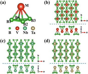 | ||
| Fig. 1 (a) Schematic diagram of MB4 structural unit. (b)–(d) Top and side views of the MB3 (M = V, Nb, and Ta) monolayers. | ||
| a | b | h | dB1–B2 | dB2–B4 | dM–B1 | dM–B4 | |
|---|---|---|---|---|---|---|---|
| VB3 | 3.918 | 2.960 | 3.304 | 1.743 | 1.809 | 2.458 | 2.319 |
| NbB3 | 4.839 | 2.982 | 3.081 | 1.713 | 1.651 | 2.606 | 2.449 |
| TaB3 | 4.834 | 2.979 | 3.071 | 1.714 | 1.652 | 2.588 | 2.452 |
Electron localization function (ELF) maps of the MB3 monolayers are plotted to investigate the bonding characteristics, as shown in Fig. 2. ELF values are normalized, where 0, 0.5, and 1 represent extremely low electron densities, completely delocalized electrons, and completely localized electrons, respectively. It can be observed that the electrons are localized between the B atoms which form strong covalent bonds. There are very few electrons around M atoms, indicating the ionic bonds between M and B atoms. It can be observed that the NbB3 and TaB3 monolayers have more localized electrons between the B2–B4 bonds of the MB4 unit compared with the VB3 monolayer, indicating a stronger interaction between B2–B4 of the NbB3 and TaB3 monolayers, as shown in the 3D ELF of Fig. 2.
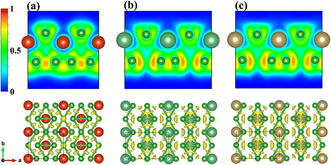 | ||
| Fig. 2 2D ELF maps of the (010) plane (up) and 3D ELF maps (down) for the (a) VB3, (b) NbB3, and (c) TaB3 monolayers. The isosurface for 3D ELF maps is selected as 0.8. | ||
3.2 Stability
The possibility of the MB3 monolayers for experimental synthesis can be demonstrated by the cohesive energy, phonon spectrum, and AIMD calculations. Our computed cohesive energies are −0.51 eV for the VB3 monolayer, −0.47 eV for the NbB3 monolayer, and −0.39 eV for the TaB3 monolayer, showing that the MB3 monolayers are thematically stable. Their dynamic stability is proved by phonon dispersion curves, as shown in Fig. S2 in ESI.† No negative frequency indicates that the MB3 monolayers are dynamically stable. The highest frequencies are up to 28.48 THz (949.99 cm−1) for the VB3 monolayer, 31.66 THz (1056.06 cm−1) for the NbB3 monolayer, and 31.64 THz (1055.40 cm−1) for the TaB3 monolayer at Γ point, which represents their outstanding stability. AIMD simulations are also shown in Fig. S2.† The integrity of their structures and their energy oscillations at equilibrium indicate that the MB3 monolayers have excellent thermodynamic stability at high temperatures.Furthermore, the mechanical stability of the MB3 monolayers is investigated by elastic constants which are listed in Table 2. There are four independent variables for the rectangular crystal system, which are c11, c12, c22, and c66, respectively. Their elastic constants satisfy stability criteria: c11 > 0, c66 > 0 and (c11c22 − c122) > 0. The corresponding 2D (in-plane) Young's moduli of MB3 monolayers are calculated by Yx = (c11c22 − c122)/c22 and Yy = (c11c22 − c122)/c11. Their Yx exceeds 100 N m−1 and Yy exceeds 300 N m−1 respectively, indicating their good mechanical stiffness. These stability calculations prove that MB3 monolayers can be synthesized as independent nanostructures. It is noted that the NbB3 and TaB3 monolayers have the larger Yx and smaller Yy compared to the VB3 monolayer, this result is consistent with the analysis of the bonding characteristics between the B2–B4 for the MB4 unit.
| c11 | c12 | c22 | c66 | Yx | Yy | |
|---|---|---|---|---|---|---|
| VB3 | 115.796 | 27.621 | 375.757 | 171.522 | 113.766 | 369.169 |
| NbB3 | 181.063 | 67.315 | 334.253 | 143.037 | 167.506 | 309.227 |
| TaB3 | 214.373 | 75.296 | 346.031 | 150.963 | 197.989 | 319.584 |
3.3 Electronic structures
The GGA and GGA + SOC methods are both considered to calculate the band structures of the MB3 monolayers which are displayed in Fig. 3. They all exhibit metal-like characteristics due to the bands crossing the Fermi level (EF), indicating high electrical conductivity. The SOC effect cannot change their metallic properties. Therefore, the MB3 monolayers have a high electronic conductance. Surprisingly, Dirac cones near the EF can be observed in the band structures of the NbB3 and TaB3 monolayers on Γ–S and Y–Γ paths in the Brillouin zone (BZ), but not in that of the VB3 monolayer.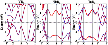 | ||
| Fig. 3 Band structures of the MB3 monolayers. The thick blue and thin red lines represent the GGA and GGA + SOC methods, respectively. | ||
3.4 Adsorption and diffusion of the single Li atom
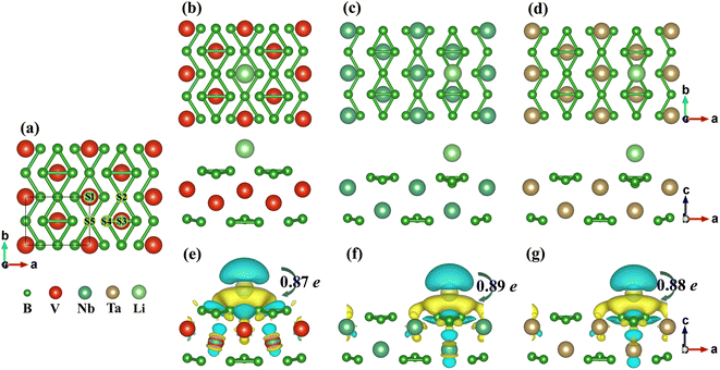
In order to study the adsorption behaviour of a single Li atom on the MB3 monolayers, a 2 × 2 × 1 supercell is selected and five atomic positions are considered after full consideration of the symmetry. As shown in Fig. 4(a), the five positions are arranged clockwise from S1 to S5. Their adsorption energies are listed in Table 3 (the value of the adsorption energies under different correction schemes are shown in Table S2–S4†). It should be noted that S4 will move to S3 for the VB3 monolayer or S5 for NbB3 and TaB3 monolayer. Therefore, only four adsorption sites will be considered (S1, S2, S3, and S5) in subsequent calculations. For the VB3 monolayer, the adsorption site with the lowest adsorption energy is S1 (on the M atoms). However, S2 (on the B1/B3 atoms) is the most favourable site for NbB3 and TaB3 monolayers. The most favourable sites of the single Li atom for the MB3 monolayers are shown in Fig. 4(b)–(d).| S1 | S2 | S3 | S4 | S5 | |
|---|---|---|---|---|---|
| VB3 | −1.418 | −0.835 | −0.432 | −0.432 | −0.439 |
| NbB3 | −0.676 | −0.933 | −0.487 | −0.833 | −0.833 |
| TaB3 | −0.620 | −0.963 | −0.456 | −0.931 | −0.931 |
The charge density difference maps of the favourite Li sites for the MB3 monolayers are also shown in Fig. 4(e)–(g). The yellow and blue areas represent the gained and lost electrons, respectively. The transfer of electrons from the Li atom to the MB3 surfaces can be observed, indicating that the Li atom forms the ionic bonds with the MB3 monolayer. Bader charge analysis can quantitatively analyze the value of the charge transfer from the Li atom to the monolayer, as shown in the black number. This reveals that the Li atom has been completely ionized on the surface, forming the Li-ions.
The diffusion barrier is an important parameter to measure the rate of charge and discharge. High-performance anode materials tend to have low diffusion barriers. According to their adsorption sites with the lowest adsorption energies, six possible diffusion paths are considered, which can be seen in Fig. 5. For the VB3 monolayer, the optimal diffusion path is path 3 whose value is 0.590 eV. However, path 5 (0.202 eV) and path 6 (0.399 eV) are the lowest energy diffusion paths for the NbB3 monolayer and TaB3 monolayer. Compared with other high-performance anode materials for LIB in theory, such as 0.50 eV for NiC3,28 0.58 eV for silicon,58 0.60 eV for χ3 borophene5 and 0.78 eV for MoN2,59 our MB3 monolayers have fast charge–discharge rates which could be anode materials for LIBs.
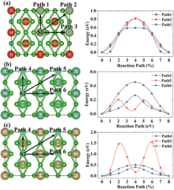 | ||
| Fig. 5 The diffusion path and diffusion barrier of a single Li-ion on the (a)VB3, (b)NbB3, and (c)TaB3 monolayers, respectively. | ||
3.5 Theoretical capacity and open-circuit voltage
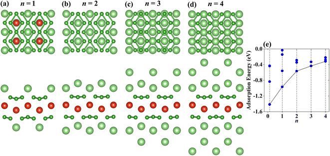
Theoretical capacity and average OCV are important indicators for electrode material, which are related to the number of adatoms and their adsorption energies. In the following discussion, we divide the VB3 monolayer into a separate group, and NbB3 and TaB3 monolayers into another group due to their differences in structural characteristics and the most stable adsorption sites. The Li atoms are stacked on both sides of the monolayer according to the above adsorption sites until these sites exposed to the surface are completely occupied, corresponding to the stoichiometries of MB3Lin (n = 1–4).The configurations of the Li atoms adsorbed on the VB3 surfaces with the lowest adsorption energies are shown in Fig. 6(a)–(d). When n = 1, the first layer Li atoms prefer to adsorb on S1. With the adatoms increasing, the second Li atomic layer is located at S4. The subsequent third and fourth layers of Li atoms are adsorbed on S5 and S2, respectively. Fig. 6(e) shows the adsorption energies of VB3Lin. With the increase of the Li content, the average adsorption energies increase gradually from −1.416 eV per Li atom (n = 0.125) to −0.317 eV per Li atom (n = 4) but still remain negative. These results demonstrate that the VB3 monolayer can adsorb four-layer Li at least. According to eqn (3), the corresponding theoretical capacity is 1286 mA h g−1 which is higher than that of VC2 (1073 mA h g−1),27 V2B2 (969 mA h g−1).36 The corresponding average OCV for VB3Li4 is 0.32 V which is suitable to be an anode material due to the value between 0 and 1 V, indicating the VB3 monolayer does not dendrite during lithiation and its capacity is reversible.52,60
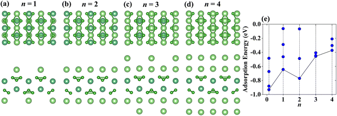
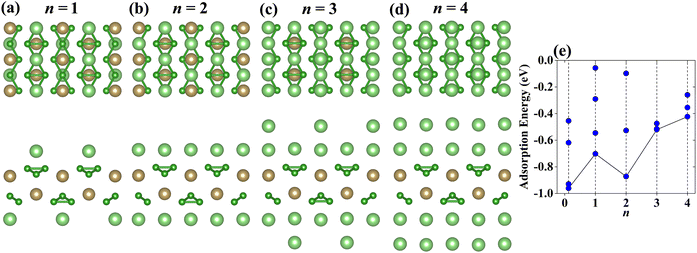
Same to the VB3 monolayer, the configurations of the Li atoms adsorbed on NbB3 and TaB3 monolayers are considered, whose most stable structures can be seen in Fig. 7(a)–(d) and 8(a)–(d). The occupy positions of Li atoms order to S2–S5–S1–S4 from the first layer to the fourth layer. The corresponding adsorption energies can be seen in Fig. 7(e) for NbB3Lin and Fig. 8(e) for TaB3Lin. With the increase of the layer number of adatom, the adsorption energies increase gradually, except for that of Nb(Ta)B3Li2 which is lower than that of Nb(Ta)B3Li. In addition, the Li atoms adsorbed on the NbB3 and TaB3 monolayers are neatly arranged, when the value n is even, which causes lower adsorption energies for Nb(Ta)B3Li2 and Nb(Ta)B3Li4 compared with VB3Li2 and VB3Li4 due to the suitable arrangement of Li atoms. The theoretical capacities of the NbB3 and TaB3 monolayers for Li-ions are 856 mA h g−1 and 502 mA h g−1, respectively. Compared with Nb and Ta carbides such as 813.12 mA h g−1 for Nb2C,22 194.36 mA h g−1 for Nb2CS2,61 264 mA h g−1 for Ta2C and 556 mA h g−1 for TaC,31 they have excellent theoretical capacities. According to eqn (4), the average OCVs for NbB3Li4 and TaB3Li4 are 0.37 V and 0.42 V, indicating that they are potential anode materials for LIBs.
The process of Li adsorption often results in a volume change of anode material, which will affect the stability during the cycling process of electrode material. Therefore, the in-plane strain (Δa: along a-direction, Δb: along b-direction) and the out-of-plane strain (Δh) during Li adsorption are obtained, which can be seen in Table S6–S8,† according to the eqn (5)–(7). The |Δa| of VB3Lin stays below 4% and |Δb| remains below 1%. The Δh of the VB3Lin monolayer increases to a maximum of 3.608% when n = 1, and decreases gradually to 0.022% when n = 4. However, the values of |Δa| and |Δb| for NbB3Lin and TaB3Lin are all below 2%. The maximum values Δh of Nb(Ta)B3Lin are 4.737% (NbB3Li2) and 5.607% (TaB3Li3), respectively. Compared with graphite (Δa ∼ 12%),62 Ti2CSSe (Δa ∼ 4.10%, Δh ∼ −2.22%), Ti2CSO (Δh ∼ 6.75%)63 and MC6 (Δa ∼ 6.30%),23 the volume change of the MB3 monolayers is small enough to be excellent anode materials.
The AIMD simulations are employed to verify the thermodynamical stability when MB3 monolayers adsorb Li atoms at 300 K, which can be seen in Fig. S3.† Compared with the highly deformed anode materials during the process of lithiation at certain temperatures, such as NiC3,28 and hydrogenated graphene-like borophene,64 the structures of the MB3 monolayers are undestroyed by Li-ions. Combined with the volume change of the Li adsorption process, it can clearly see that the MB3 monolayer will not cause safety problems when working as an anode material due to volume change (Table 4).
Conclusion
In conclusion, we design boron-rich MB3 monolayers (M = V, Nb and Ta) and explore their electrochemical performance as anode materials for LIBs, using the structural prediction method and first-principles calculations. The MB3 monolayers are stable which is verified by cohesive energies, phonon dispersions, molecular dynamics simulations and elastic constants, respectively. The high Young's moduli of MB3 monolayers mean they have high stiff enough. Electronic structure calculations show that the MB3 monolayers have metal-like conduction. Furthermore, the low diffusion barriers and suitable average open-circuit voltages suggest that they could be promising anode materials for LIBs. Most importantly, the theoretical capacities are 1286 mA h g−1 (VB3Li4), 856 mA h g−1 (NbB3Li4) and 502 mA h g−1 (TaB3Li4) which are higher than a lot of 2D anode materials for LIBs. Our work has enriched the study of MBenes as anode materials and provided certain guidance for future theoretical and experimental studies.Conflicts of interest
There are no conflicts to declare.Acknowledgements
This work was partially supported by the National Nature Science Foundation of China (No. 52072099), the Natural Science Foundation of Heilongjiang Province (No. LH2021A016), and the subject of Harbin Normal University under Grant (No. 2020-KYYWF-0352). The calculations were carried out using supercomputer resource provided by the High-performance Computing Center of Harbin Normal University.References
- L. Lu, X. Han, J. Li, J. Hua and M. Ouyang, J. Power Sources, 2013, 226, 272–288 Search PubMed.
- M. Winter, J. O. Besenhard, M. E. Spahr and P. Novμk, Adv. Mater., 1998, 10, 725–763 Search PubMed.
- C. Ma, X. Shao and D. Cao, J. Mater. Chem., 2012, 22, 8911 Search PubMed.
- R. Mas-Balleste, C. Gomez-Navarro, J. Gomez-Herrero and F. Zamora, Nanoscale, 2011, 3, 20–30 Search PubMed.
- X. Zhang, J. Hu, Y. Cheng, H. Y. Yang, Y. Yao and S. A. Yang, Nanoscale, 2016, 8, 15340–15347 Search PubMed.
- J. Liu, C. Zhang, L. Xu and S. Ju, RSC Adv., 2018, 8, 17773–17785 Search PubMed.
- A. Y. Galashev and A. S. Vorob'ev, Electrochim. Acta, 2021, 378, 138143 Search PubMed.
- S. Deng, L. Wang, T. Hou and Y. Li, J. Phys. Chem. C, 2015, 119, 28783–28788 Search PubMed.
- D. Wang, L. M. Liu, S. J. Zhao, B. H. Li, H. Liu and X. F. Lang, Phys. Chem. Chem. Phys., 2013, 15, 9075–9083 Search PubMed.
- E. Yang, H. Ji and Y. Jung, J. Phys. Chem. C, 2015, 119, 26374–26380 Search PubMed.
- X. Lv, W. Wei, Q. Sun, B. Huang and Y. Dai, J. Phys. D: Appl. Phys., 2017, 50, 235501 Search PubMed.
- G. Barik and S. Pal, J. Phys. Chem. C, 2019, 123, 21852–21865 Search PubMed.
- M. Naguib, M. Kurtoglu, V. Presser, J. Lu, J. Niu, M. Heon, L. Hultman, Y. Gogotsi and M. W. Barsoum, Adv. Mater., 2011, 23, 4248–4253 Search PubMed.
- Y. Xie, Y. Dall'Agnese, M. Naguib, Y. Gogotsi, M. W. Barsoum, H. L. Zhuang and P. R. C. Kent, ACS Nano, 2014, 8, 9606–9615 Search PubMed.
- Z. Yang, Y. Zheng, W. Li and J. Zhang, Nanoscale, 2021, 13, 11534–11543 Search PubMed.
- K. Rajput, V. Kumar, S. Thomas, M. A. Zaeem and D. R. Roy, 2D Mater., 2021, 8, 035015 Search PubMed.
- D. Çakır, C. Sevik, O. Gülseren and F. M. Peeters, J. Mater. Chem. A, 2016, 4, 6029–6035 Search PubMed.
- D. Er, J. Li, M. Naguib, Y. Gogotsi and V. B. Shenoy, ACS Appl. Mater. Interfaces, 2014, 6, 11173–11179 Search PubMed.
- D. Sun, M. Wang, Z. Li, G. Fan, L. Z. Fan and A. Zhou, Electrochem. Commun., 2014, 47, 80–83 Search PubMed.
- J. Zhao, J. Wen, J. Xiao, X. Ma, J. Gao, L. Bai, H. Gao, X. Zhang and Z. Zhang, J. Energy Chem., 2021, 53, 387–395 Search PubMed.
- M. Naguib, J. Halim, J. Lu, K. M. Cook, L. Hultman, Y. Gogotsi and M. W. Barsoum, J. Am. Chem. Soc., 2013, 135, 15966–15969 Search PubMed.
- L. Bai, H. Yin, L. Wu and X. Zhang, Comput. Mater. Sci., 2018, 143, 225–231 Search PubMed.
- Q. Tang, Z. Zhou and P. Shen, J. Am. Chem. Soc., 2012, 134, 16909–16916 Search PubMed.
- F. Kong, X. He, Q. Liu, X. Qi, Y. Zheng, R. Wang and Y. Bai, Electrochim. Acta, 2018, 265, 140–150 Search PubMed.
- H. Huang, H. H. Wu, C. Chi, B. Huang and T. Y. Zhang, J. Mater. Chem. A, 2019, 7, 8897–8904 Search PubMed.
- S. Lu, C. Yang, D. Fan and X. Hu, Phys. Chem. Chem. Phys., 2019, 21, 15187–15194 Search PubMed.
- J. Xu, D. Wang, R. Lian, X. Gao, Y. Liu, G. Yury, G. Chen and Y. Wei, J. Mater. Chem. A, 2019, 7, 8873–8881 Search PubMed.
- C. Zhu, X. Qu, M. Zhang, J. Wang, Q. Li, Y. Geng, Y. Ma and Z. Su, J. Mater. Chem. A, 2019, 7, 13356–13363 Search PubMed.
- F. Zhang, T. Jing, S. Cai, M. Deng, D. Liang and X. Qi, Phys. Chem. Chem. Phys., 2021, 23, 12731–12738 Search PubMed.
- Y. Yu, Z. Guo, Q. Peng, J. Zhou and Z. Sun, J. Mater. Chem. A, 2019, 7, 12145–12153 Search PubMed.
- T. Yu, S. Zhang, F. Li, Z. Zhao, L. Liu, H. Xu and G. Yang, J. Mater. Chem. A, 2017, 5, 18698–18706 Search PubMed.
- Z. Guo, J. Zhou and Z. Sun, J. Mater. Chem. A, 2017, 5, 23530–23535 Search PubMed.
- S. F. Wang, B. T. Wang, T. Bo, J. R. Zhang and F. W. Wang, Appl. Surf. Sci., 2021, 538, 148048 Search PubMed.
- N. Ma, T. Wang, N. Li, Y. Li and J. Fan, Appl. Surf. Sci., 2022, 571, 151275 Search PubMed.
- T. Bo, P. F. Liu, J. Xu, J. Zhang, Y. Chen, O. Eriksson, F. Wang and B. T. Wang, Phys. Chem. Chem. Phys., 2018, 20, 22168–22178 Search PubMed.
- J. Jia, B. Li, S. Duan, Z. Cui and H. Gao, Nanoscale, 2019, 11, 20307–20314 Search PubMed.
- S. Gao, J. Hao, X. Zhang, L. Li, C. Zhang, L. Wu, X. Ma, P. Lu and G. Liu, Comput. Mater. Sci., 2021, 200, 110776 Search PubMed.
- G. Yuan, T. Bo, X. Qi, P. F. Liu, Z. Huang and B. T. Wang, Appl. Surf. Sci., 2019, 480, 448–453 Search PubMed.
- R. Li, Y. Wang, L. C. Xu, J. Shen, W. Zhao, Z. Yang, R. Liu, J. L. Shao, C. Guo and X. Li, Phys. Chem. Chem. Phys., 2020, 22, 22236–22243 Search PubMed.
- Y. Wang, J. Lv, L. Zhu and Y. Ma, Comput. Phys. Commun., 2012, 183, 2063–2070 Search PubMed.
- Y. Wang, J. Lv, L. Zhu and Y. Ma, Phys. Rev. B, 2010, 82, 094116 Search PubMed.
- B. Gao, P. Gao, S. Lu, J. Lv, Y. Wang and Y. Ma, Sci. Bull., 2019, 64, 301–309 Search PubMed.
- G. Kresse and J. Furthmüller, Comput. Mater. Sci., 1996, 6, 15–50 Search PubMed.
- G. Kresse and J. Furthmüller, Phys. Rev. B, 1996, 54, 11169–11186 Search PubMed.
- G. Kresse and D. Joubert, Phys. Rev. B, 1999, 59, 1758–1775 Search PubMed.
- J. P. Perdew, J. A. Chevary, S. H. Vosko, K. A. Jackson, M. R. Pederson, D. J. Singh and C. Fiolhais, Phys. Rev. B: Condens. Matter Mater. Phys., 1992, 46, 6671–6687 Search PubMed.
- J. P. Perdew, K. Burke and M. Ernzerhof, Phys. Rev. Lett., 1996, 77, 3865–3868 Search PubMed.
- S. Grimme, J. Comput. Chem., 2006, 27, 1787–1799 Search PubMed.
- A. Togo and I. Tanaka, Scr. Mater., 2015, 108, 1–5 Search PubMed.
- G. Henkelman, B. P. Uberuaga and H. Jonsson, J. Chem. Phys., 2000, 113, 9901 Search PubMed.
- V. Wang, N. Xu, J. C. Liu, G. Tang and W. T. Geng, Comput. Phys. Commun., 2021, 267, 108033 Search PubMed.
- T. Yu, Z. Zhao, L. Liu, S. Zhang, H. Xu and G. Yang, J. Am. Chem. Soc., 2018, 140, 5962–5968 Search PubMed.
- Y. Wang, L. Wu, Y. Lin, Q. Hu, Z. Li, H. Liu, Y. Zhang, H. Gou, Y. Yao, J. Zhang, F. Gao and H. Mao, Phys. Rev. B, 2015, 92, 174106 Search PubMed.
- J.-O. Joswig and M. Springborg, J. Chem. Phys., 2008, 129, 134311 Search PubMed.
- C. Zhang, S. Zhang and Q. Wang, Sci. Rep., 2016, 6, 29531 Search PubMed.
- J. Jia, S. Wei, Q. Cai and J. Zhao, J. Colloid Interface Sci., 2021, 600, 711–718 Search PubMed.
- Z. Gao, F. Ma, X. Zhang, Z. Tian, Y. Liu, Y. Jiao and A. Du, Phys. E, 2021, 134, 114930 Search PubMed.
- O. I. Malyi, T. L. Tan and S. Manzhos, Appl. Phys. Express, 2013, 6, 027301 Search PubMed.
- X. Zhang, Z. Yu, S. S. Wang, S. Guan, H. Y. Yang, Y. Yao and S. A. Yang, J. Mater. Chem. A, 2016, 4, 15224–15231 Search PubMed.
- Z. Zhao, T. Yu, S. Zhang, H. Yu, G. Yang and Y. Liu, J. Mater. Chem. A, 2019, 7, 405 Search PubMed.
- Y. Jing, J. Liu, Z. Zhou, J. Zhang and Y. Li, J. Phys. Chem. C, 2019, 123, 26803–26811 Search PubMed.
- Y. Zhang, G. Mo, X. Li, W. Zhang, J. Zhang, J. Ye, X. Huang and C. Yu, J. Power Sources, 2011, 196, 5402–5407 Search PubMed.
- E. M. D. Siriwardane and J. Hu, J. Phys. Chem. C, 2021, 125, 12469–12477 Search PubMed.
- M. Makaremi, B. Mortazavi and C. V. Singh, Mater. Today Energy, 2018, 8, 22–28 Search PubMed.
Footnote |
| † Electronic supplementary information (ESI) available. See https://doi.org/10.1039/d2ra05111g |
| This journal is © The Royal Society of Chemistry 2022 |

