 Open Access Article
Nitrogen and titanium-codoped porous carbon nanocomposites derived from metal–organic framework as cathode to address polysulfides shuttle effects by Ti-assisted N-inhibiting strategy†
Meng-Ting Li *ab,
Jun Chena,
Ke Rena,
Xian-Hong Lia,
Hai-Yang Gaoa,
Da-Qiang Sunb and
Yang Yu*a
aCollege of Chemistry and Chemical Engineering, Qufu Normal University, Qufu, 273165, People's Republic of China. E-mail: limt0205@qfnu.edu.cn
bShandong Sacred Sun Power Sources Co., Ltd, No. 1, Shengyang Road, Qufu, Shandong 273100, China
First published on 15th December 2022
Abstract
To address the problem of shutting effect of Li–S batteries, we used Ti-based MOF as precursor to obtain a conductive matrix with dual inhibitors. The target material, namely NTiPC, shown remarkable discharge capacity with 1178 mA h g−1, and maintained at 732 mA h g−1 after 100 cycles. The results indicated the N- and Ti-active sites synergistic acted with conductive framework can facilitate binding reaction between matrix and polysulfides.
Introduction
Lithium–sulfur (Li–S) batteries, one of the main branches of second-generation rechargeable batteries, have rapidly drawn widespread attention in recent years, owing to their high theoretical capacity (∼1675 mA h g−1), low cost, almost non-toxic and abundant reserves in nature.1,2 Despite the numerous advantages, the shuttle phenomenon of polysulfides greatly restricts the industrialization of Li–S batteries from perspective of reality.3–5 Much efforts have been tried in physically and/or chemically block the dissolution of polysulfides.6–8 This strategy is mainly to confine the guest molecular, such as microporous carbon.9,10 Whereas, the weak interaction between carbonic skeleton and polysulfides conduces a significant decay on the basis of long term cycling.11,12 N-doped carbons, can act as effective shuttle effect inhibitor owing to strong binding with polysulfides species.13,14 Moreover, transition metal oxides (TMOs) have also been studied due to the strong binding capabilities with polysulfide.15–17 However, these materials are controversial because of their undefined structure. In particular, conventional approaches to make porous carbon, such as template synthesis, are often complex and involve highly toxic substances, which impedes the use of the materials mentioned above as sulfur hosts for commercial Li–S batteries.18Instead of adopting active sites (N- or TMOs) doped porous carbon materials as the host of sulfur followed by traditional synthesis method, the use of metal–organic frameworks (MOFs) with ordered crystalline structures as precursor have been certified to make framework structures and active elements distribute more uniformly, improve sulfur utilization and facilitate the kinetics of the Li–S redox reaction.19,20 MOFs, with metallic centers and redox active organic linkers, is already proven to be used in the field of electrode materials.21,22 As ideal host materials, MOFs with long range ordered channels to fabricate cathode composites can confine the polysulfides species through the confinement effect.23,24 Nevertheless, the inherent insulating properties of crystalline MOFs limit their electrochemical performance as host for sulphur.25 Hence, modulating the conductivity of MOFs while inheriting part of its structural and physicochemical characteristics is an effective way to adjust the host of sulfur.
Based on these, we attempted to use a nitrogen- and titanium-codoped porous carbon nanocomposites, which derived from Ti-based MOFs, as host to accommodate large amounts of sulfur. By using this Ti-assisted N-inhibiting strategy, nitrogen and titanium-doped porous carbon exhibiting incredible reversible charge/discharge performance, capacity retention ability and high electronic conductivity.
Experimental
MIL-125(Ti)
MIL-125(Ti) was prepared by reported in previous literature with slight alteration.26 A mixed solvent consisting of 18 ml DMF (N,N′-dimethylformamide) and 2 ml dry MeOH was used for solvent method. The mixture of 1.5 mmol tetra-n-butyl titanate (Ti(OC4H9)4), 6 mmol terephthalic acid (H2BDC) and component solvent was stirring for 0.5 h at room temperature. After that, transferred the mixture into Teflon-lined stainless steel reactor and kept at 150 °C for 15 h. The products were cleaned with DMF and methanol several times, filtered and separated. After vacuum drying at 120 °C, the white powders was obtained.NH2-MIL-125(Ti)
NH2-MIL-125(Ti), yellow solid products, is isomorphic to MIL-125(Ti), which obtained by substituting NH2BDC for H2BDC.27Ti-doped porous carbon (TiPC), N- and Ti-codoped porous carbon (NTiPC)
The as-synthesized Ti-MOFs were heated to 900 °C with a 4 °C min−1 heating rate, and maintained the temperature for 2 h under the protection of argon gas flow. After natural cooling, pure black powders of TiPC and NTiPC were collected.S/MIL-125(Ti), S/TiPC, S/NH2-MIL-125(Ti) and S/NTiPC cathodes
According to the description reported by Wang et al.,28 we preparation a series of cathodes materials. The mixture of samples (MIL-125(Ti), TiPC, NH2-MIL-125(Ti), NTiPC) and sulfur (m/m = 1![[thin space (1/6-em)]](https://www.rsc.org/images/entities/char_2009.gif) :
:![[thin space (1/6-em)]](https://www.rsc.org/images/entities/char_2009.gif) 1) were ground in the quartz mortar and heated to 155 °C under argon for maximum 12 h, respectively.
1) were ground in the quartz mortar and heated to 155 °C under argon for maximum 12 h, respectively.
Materials characterizations
Crystalline phase features of the samples were confirmed by X-ray powder diffraction (XRD, PANalytical X-ray Diffractometer Model X pert3). The morphologies of compounds were photo via field emission scanning electron microscopy (SEM, Sigma 500 VP). The distribution of elements on the surface of the samples were measured by Energy Dispersive X-ray spectroscopy (EDX). Oxidation states of the elements were demonstrated by X-ray photoelectron spectroscopy (XPS, Thermo-Fisher ESCALAB250xi). The sulfur loading in the as-samples was detected by thermogravimetric analysis (TGA, Perkin-Elmer TG-7 analyzer). Quantachrome Instrument (Quabrasorb SI-3MP) were employed to characterize N2 adsorption/desorption measurements.Results and discussion
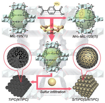
In this work we aimed at encapsulating sulfur within the matrix of N- and Ti-codoped porous carbon. For this purpose, we designed to use a typical Ti-based MOF, NH2-MIL-125(Ti) as precursor, to mitigate shuttle effect by Ti-assisted N-inhibiting strategy. The products analysis and phase purity of the as-synthesized MIL-125(Ti) and NH2-MIL-125(Ti) have been confirmed by XRD patterns as shown in Fig. S1.† The patterns of MIL-125(Ti) and NH2-MIL-125(Ti) are matching well to the previous reports,29–31 which identified the successfully synthesis of precursor. Ti8O8(OH)412+ cluster and H2BDC construct an octahedral cage, and then expand to 3D porous framework (Fig. 1). Besides, the presence of NH2– groups did not influence the architecture, so that MIL-125(Ti) and NH2-MIL-125(Ti) have isomorphic structures. In order to uniformly disperse nitrogen and titanium elements in the framework, MIL-125(Ti) and NH2-MIL-125(Ti) were used as precursor. After the sulfur loading process, we obtained the cathodes. And the XRD diffraction peaks of S/MIL-125(Ti) and S/NH2-MIL-125(Ti) still obviously inosculate with micro crystalline MOFs, which represent the successful loading of sulphur. The XRD patterns of TiPC and NTiPC show the patterns of carbon materials. The XRD of S/TiPC and S/NTiPC can observe the characteristic diffraction peaks of sulfur.Brunauer–Emmett–Teller (BET) specific surface area of as-prepared TiPC and NTiPC are 546 and 414 m2 g−1 respectively (Fig. S2†). A considerable decrease in BET surface area for NH2-MIL-125(Ti) was caused by the presence of amine groups inside of the matrix. However, the specific surface area of S/TiPC and S/NTiPC are only 12 and 13 m2 g−1, which is demonstrated the successfully encapsulated of sulfur. Therefore, the sufficient sulfur loading could be ensured. The isotherms exhibit types I sorption behaviour typical for microporous materials. Both TiPC and NTiPC have average pore size of approximately 5 nm.
According to TGA (Fig. S3†), all of the as-synthesized and prepared materials possess approximately 50 wt% loading quantitative of sulfur. Based on the reported by Fu et al., the main weight loss of MIL-125(Ti) and NH2-MIL-125(Ti) are higher than 300 °C,32 so the pretreatment samples without solvent molecules were tested at the thermal weight loss range of sulfur. XRD patterns further demonstrated the successfully loading of sulfur. The experimental diffraction pattern of S/MIL-125(Ti) and S/NH2-MIL-125(Ti) are obeyed with the Ti-based MOFs. It means that the structural integrity is maintained in time of sulfur encapsulation procedure. In addition, TiPC and NTiPC show amorphous carbon materials pattern, and diffraction peaks of sulfur appear in S/TiPC and S/NTiPC, which confirmed the successful loading of sulfur (Fig. S1†).
Scanning electron microscopy (SEM) morphologies show the images of Ti-based MOFs, TiPC, NTiPC, S/TiPC and S/NTiPC as shown in Fig. 2 and S4.† The synthesized MIL-125(Ti) exhibit well-defined disk-like morphology, and the NH2-MIL-125(Ti) play a square piece morphology. After calcination, TiPC and NTiPC inherit the shape of precursors. There is no obvious sulfur aggregation but a highly dispersed state on the surface of the samples. This phenomenon is usually unavoidable in one-step homologous thermal decomposition.33–35
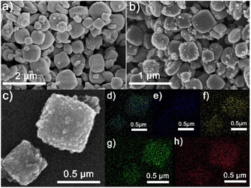 | ||
| Fig. 2 SEM images of NH2-MIL-125(Ti) (a), NTiPC (b) and S/NTiPC (c), respectively. The elemental mapping of carbon (d), nitrogen (e), oxygen (f), titanium (g) and sulfur (h) of S/NTiPC. | ||
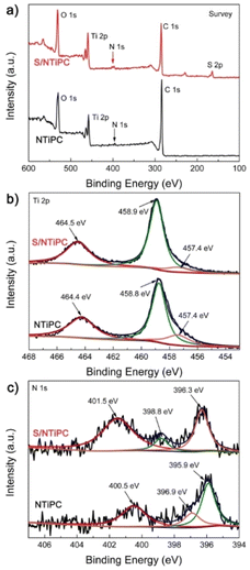
The distribution of different elements in the S/TiPC and S/NTiPC is investigated by energy-dispersive X-ray (EDX) spectroscopy mapping analysis. The uniform distributions of N and Ti elements suggest that the NTiPC matrix are formed in almost all particles. The strong EDX signal of sulfur in these composites imply the large amount of sulfur in the final cathodes. The XPS survey spectra reveals the surface chemical composition and functional groups of the NTiPC and S/NTiPC composites. The result shows that the presence of N-, C-, O-, S- and Ti-related peaks in the survey spectra (Fig. 3a). The peaks at 164 and 228 eV for S/NTiPC are attributed to S 2p and S 2s, respectively. The doublet peaks observed at 458.8 and 464.4 eV in NTiPC, and the peaks at 458.9 and 464.5 eV in S/NTiPC were characteristic of the TiO2 species (Fig. 3b). Another minor feature located at 457.4 eV in both NTiPC and S/NTiPC was attributed to a Ti2O3 surface phase. The there peaks at 400.5 eV, 396.9 eV and 395.9 eV in the N 1s spectrum of NTiPC (Fig. 3c) indicated the presence of quaternary N, pyrrolic N and pyridinic N species, respectively. The peaks at 401.5 eV, 398.8 eV and 396.3 eV in the N 1s spectrum of S/NTiPC are in the same circumstance. The N- and Ti-doped dual active sites are considered to enhance the binding strength and energy of the nonpolar atoms of host with polar polysulphides of guest, thus significantly increasing the long-cycle stability.
To investigated the electrochemical behavior of TiPC and NTiPC, we adopted a series of contrast materials to eliminate other factors. Such as anatase TiO2, unprocessed carbon and as-prepared Ti-MOFs precursor. Cyclic voltammetry (CV) analysis was used to prove the discharge/charge cycling performance and the presence of active substances of sulphur in a half cell. As shown in Fig. 4, all of the cathode materials showed obvious characteristic redox peaks of Li–S batteries, which is the working voltage range of the cells cycled at low rates. The characteristic reduction peaks at 2.3 V and 2.0 V are belonging to the multistep reduction of sulfur with Li.36,37 The oxidation peak approximately 2.4 V vested in reaction behaviour. The oxidation peak of S/MIL-125(Ti) and S/NH2-MIL-125(Ti) cathodes accompanies a broad peak starting at 2.3 V to 2.6 V, which is believed to be a feature of the active material within confined structures.38 Notably, the peaks of S/NTiPC at 5th cycle matches well with the initial ones without barely position offset or dramatically intensity decrease. Thus, NTiPC as host, possesses excellent electrochemical stability which attributed to the Ti-assisted N-inhibiting strategy and confinement effect of derivative framework. SEM images indicate that the morphology of NTiPC remained stable after several cycles of discharge/charge cycling (Fig. S5†).
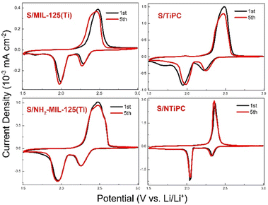 | ||
| Fig. 4 CV curves of in a range of S/MIL-125(Ti), S/TiPC, S/NH2-MIL-125(Ti) and S/NTiPC cathodes 1.5–3 V with a scanning rate of 0.1 mV s−1. | ||
Nyquist profiles of AC impedance represent the dynamics performance of batteries (Fig. S6†). The charge transfers resistance (Rct) of S/MIL-125(Ti), S/TiPC, S/NH2-MIL-125(Ti) and S/NTiPC cathodes at the first cycle are 70.1 Ω cm−2, 38.8 Ω cm−2, 259.9 Ω cm−2, 112.7 Ω cm−2, 99.3 Ω cm−2, 28.5 Ω cm−2, respectively. The Rct of NTiPC and S/NTiPC cathodes are almost the same, which lower than other cathodes materials and have better electrical conductivity. Obviosity, the Rct value is higher when micro crystalline Ti-MOFs used as anode materials directly. After high-temperature carbonization, NTiPC derived from Ti-MOFs can reduce the resistance of electron transfer and bring out lowest Rct value. Furthermore, the N- and Ti-active sites synergistic acted with conductive matrix can facilitate the electrolyte infiltration, which has triggered the easily interface ion transfer and leaded to a lower Rct.
When evaluated as cathode of Li–S batteries, NTiPC nanocomposite exhibits excellent discharge/charge capacity and cycling performance at 0.5 C-rate (1C = 1672 mA h g−1) in the voltage window of 1.5–3 V (Fig. 5). The capacity decay of S/TiO2 is dramatically, even though it possesses the highest discharge capacity of 1271 mA h g−1 at 1st cycle (Fig. S7†). It can only be maintained at approximately 510 mA h g−1 after 40 cycles. The discharge capacity of battery with the S/carbon cathode is at most 636.9 mA h g−1, but its capacity retention ability is good.
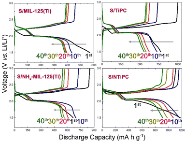 | ||
| Fig. 5 Discharge/charge curves of the S/MIL-125(Ti), S/TiPC, S/NH2-MIL-125(Ti) and S/NTiPC cathodes at different cycles at 0.5C. | ||
The discharge capacities of S/MIL-125(Ti), S/TiPC, S/NH2-MIL-125(Ti) and S/NTiPC cathodes at 1st cycle is 568, 928, 800 and 1178 mA h g−1, respectively. By contrast, S/NH2-MIL-125(Ti) cathode has higher discharge capacity and retention rate to S/MIL-125(Ti), which provides N-active sites are favourable inhibitor of polysulfide shuttle. The contrast between microcrystalline MIL-125 and TiPC derivatives is well illustrated that the TiO2 as active sites could be uniformly dispersed in the conductive matrix after carbonization. And that makes a lot of sense why the S/NTiPC cathode exhibited a remarkable discharge capacity and a proper capacity retention ratio. After 40 cycles the capacity of S/NTiPC cathode as high as 912 mA h g−1.
After 100 cycles, the capacity of S/NTiPC cathode still stands at 732 mA h g−1 with nearly 100% coulombic efficiency, which is extremely better than that S/TiPC cathode with value of 456 mA h g−1 (Fig. 6). The capacity of S/TiO2 and S/carbon remain to be only 376 and 472 mA h g−1 after long discharge/charge process, demonstrating the derivative matrix with N- and Ti-codoped sites is the main contributor to the overall capacity. In addition, while S/NH2-MIL-125(Ti) can maintain at 445 mA h g−1, and S/MIL-125(Ti) can only maintain at 358 mA h g−1. It means that co-doped strategy is double insurance for capacities retention. Cycling performance at higher rate is necessary to evaluate. The experimental results show that the discharge capacity of the battery decreases obviously with the increase of current density, especially at higher rate, and the capacity retention rate is only about 50% (Fig. S8†). When the sulfur doping mass ratio of the NTiPC (at 900 °C for 2 h) is 1![[thin space (1/6-em)]](https://www.rsc.org/images/entities/char_2009.gif) :
:![[thin space (1/6-em)]](https://www.rsc.org/images/entities/char_2009.gif) 3, the initial discharge capacity is more than 1600 mA h g−1. But the decay rate is very fast, and the capacity retention rate is only 25% (Fig. S9†). It is due to the overloading of sulfur, which causes most of the sulfur to simply adhere to the surface of the material, rather than in the pores. Under the same sulfur-carrying mass ratio and carbonization temperature condition, when the carbonization time increases, the cyclic stability of the material is improved, but the specific discharge capacity decreases sharply. We speculate that the reason for this phenomenon is that the carbonization of the material for a long time leads to the aggregation of the active sites within the material, which cannot effectively inhibit the shuttle of polysulfides. In addition, if the carbonization temperature of the material is lower than 900 °C, the specific discharge capacity of S/NTiPC cathode is also relatively low.
3, the initial discharge capacity is more than 1600 mA h g−1. But the decay rate is very fast, and the capacity retention rate is only 25% (Fig. S9†). It is due to the overloading of sulfur, which causes most of the sulfur to simply adhere to the surface of the material, rather than in the pores. Under the same sulfur-carrying mass ratio and carbonization temperature condition, when the carbonization time increases, the cyclic stability of the material is improved, but the specific discharge capacity decreases sharply. We speculate that the reason for this phenomenon is that the carbonization of the material for a long time leads to the aggregation of the active sites within the material, which cannot effectively inhibit the shuttle of polysulfides. In addition, if the carbonization temperature of the material is lower than 900 °C, the specific discharge capacity of S/NTiPC cathode is also relatively low.
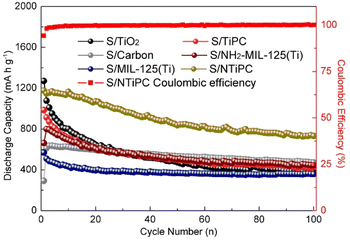 | ||
| Fig. 6 The discharge capacity of S/MIL-125(Ti), S/TiPC, S/NH2-MIL-125(Ti) and S/NTiPC cathodes and the coulombic efficiency of S/NTiPC cathode at 0.5C during 100 cycles. | ||
The rate cycling capabilities of these cathodes are investigated at different current density from 0.2 to 1C (Fig. S10†). The average capacities of S/NTiPC are 1350, 1007, 832 and 689 mA h g−1 at 0.2C, 0.5C, 0.8C and 1C rates respectively, indicating a high charge/discharge capability. When the current density was resettled to 0.2C, S/NTiPC can be resumed to 989 mA h g−1, that the structure of NTiPC still stable after suffering high current density test. In comparison, the average discharge capacities for S/TiPC at different rates are 700, 507, and 397 mA h g−1, and capacities for S/MIL-125(Ti) are 566, 421, 382 and 356 mA h g−1, and capacities for S/NH2-MIL-125(Ti) are 901, 655, 563 and 494 mA h g−1 respectively. In short, by using N- and Ti-active sites as dual-inhibitors, NTiPC can effectively mitigate the polysulfides shuttle effects.
Conclusions
To address the problem of shutting effect of Li–S batteries, we designed and synthesised a nitrogen- and titanium-codoped porous carbon material as host for mitigating the sulfur decay by Ti-assisted N-inhibiting strategy. By using NH2-MIL-125(Ti) as precursor, NTiPC has been obtained and shown remarkable discharge capacity of 1178 mA h g−1 at low current density. The results indicated the N- and Ti-active sites synergistic acted with conductive matrix can facilitate the electrolyte infiltration, which has triggered the easily interface ion transfer, strong binding with polysulfides, and significantly inhibiting the shutting phenomenon in Li–S batteries.Conflicts of interest
There are no conflicts to declare.Acknowledgements
This work was financially supported by the National Natural Science Foundation of China (21901139, 21671034), National Key Basic Research Program of China (No. 2013CB834802), the Fundamental Research Funds for the Central Universities (2412016KJ041), Changbai Mountain Scholars of Jilin Province.Notes and references
- W. Weng, J. Xiao, Y. Shen, X. Liang, T. Lv and W. Xiao, Angew. Chem., Int. Ed., 2021, 60, 1 CrossRef PubMed.
- L. Peng, Z. Yu, M. Zhang, S. Zhen, J. Shen, Y. Chang, Y. Wang, Y. Deng and A. Li, Nanoscale, 2021, 13, 16696 RSC.
- X. Yang, J. Luo and X. Sun, Chem. Soc. Rev., 2020, 49, 2140 RSC.
- M. L. Jana, R. Xu, X. B. Cheng, J. S. Yeon, J. M. Park, J. Q. Huang, Q. Zhang and H. S. Park, Energy Environ. Sci., 2020, 13, 1049 RSC.
- J. Sun, Y. Sun, M. Pasta, G. Zhou, Y. Li, W. Liu, F. Xiong and Y. Cui, Adv. Mater., 2016, 28, 9797 CrossRef CAS PubMed.
- T. Lei, Y. Xie, X. Wang, S. Miao, J. Xiong and C. Yan, Small, 2017, 13, 1701013 CrossRef PubMed.
- H. Jo, Y. Cho, T. Yoo, Y. Jeon, H. Hong and Y. Piao, ACS Appl. Mater. Interfaces, 2021, 13, 47593 CrossRef CAS PubMed.
- Q. Wu, Z. Yao, X. Zhou, J. Xu, F. Cao and C. Li, ACS Nano, 2020, 14, 3365 CrossRef CAS PubMed.
- M. Zheng, Y. Chi, Q. Hu, H. Tang, X. Jiang, L. Zhang, S. Zhang, H. Pang and Q. Xu, J. Mater. Chem. A, 2019, 7, 17204 RSC.
- M. Yu, S. Zhou, Z. Wang, W. Pei, X. Liu, C. Liu, C. Yan, X. Meng, S. Wang, J. Zhao and J. Qiu, Adv. Funct. Mater., 2019, 29, 1905986 CrossRef CAS.
- J. Zhang, H. Hu, Z. Li and X. Lou, Angew. Chem., Int. Ed., 2016, 55, 3982 CrossRef CAS PubMed.
- X. Liang, C. Kwok, F. Lodi-Marzano, Q. Pang, M. Cuisinier, H. Huang, C. J. Hart, D. Houtarde, K. Kaup, H. Sommer, T. Brezesinski, J. Janek and L. F. Nazar, Adv. Energy Mater., 2015, 5, 1501636 Search PubMed.
- J. Wang and W. Han, Adv. Funct. Mater., 2021, 2107166 Search PubMed.
- L. Kong, C. Yan, J. Huang, M. Zhao, M. Titirici, R. Xiang and Q. Zhang, Energy Environ. Mater., 2018, 1, 100 CrossRef CAS.
- Y. Yi, Z. Liu, P. Yang, T. Wang, X. Zhao, H. Huang, Y. Cheng, J. Zhang and M. Li, J. Energy Chem., 2020, 45, 18 CrossRef.
- Y. Song, W. Zhao, L. Kong, L. Zhang, X. Zhu, Y. Shao, F. Ding, Q. Zhang, J. Sun and Z. Liu, Energy Environ. Sci., 2018, 12, 2620 RSC.
- M. Kim, J. Lee, Y. Jeon and Y. Piao, Nanoscale, 2019, 11, 13758 RSC.
- W. Xia, B. Qiu, D. Xia and R. Zou, Sci. Rep., 2013, 3, 1 Search PubMed.
- C. Wen, X. Du, F. Wu, L. Wu, J. Li and G. Liu, ACS Appl. Mater. Interfaces, 2021, 13, 44389 CrossRef CAS PubMed.
- Z. Zheng, H. Ye and Z. Guo, Energy Environ. Sci., 2021, 14, 1835 RSC.
- Y. Zheng, S. Zheng, H. Xue and H. Pang, J. Mater. Chem. A, 2019, 7, 3469 RSC.
- S. Hu, Y. Hu, X. Liu and J. Zhang, Nanoscale, 2021, 13, 10849 RSC.
- S. Kim, J. Yeon, R. Kim, K. Choi and H. Park, J. Mater. Chem. A, 2018, 6, 24971 RSC.
- Y. Li, S. Lin, D. Wang, T. Gao, J. Song, P. Zhou, Z. Xu, Z. Yang, N. Xiao and S. Guo, Adv. Mater., 2020, 32, 1906722 CrossRef CAS PubMed.
- Z. Ye, Y. Jiang, L. Li, F. Wu and R. Chen, Nano-Micro Lett., 2021, 13, 203 CrossRef CAS PubMed.
- Y. Fu, D. Sun, Y. Chen, R. Huang, Z. Ding, X. Fu and Z. Li, Angew. Chem., 2012, 51, 3364 CrossRef CAS PubMed.
- Y. Han, L. Han, L. Zhang and S. Dong, J. Mater. Chem. A, 2015, 3, 14669 RSC.
- J. Zhou, R. Li, X. Fan, Y. Chen, R. Han, W. Li, J. Zheng, B. Wang and X. Li, Energy Environ. Sci., 2014, 7, 2715 RSC.
- F. Jeremias, V. Lozan, S. K. Henninger and C. Janiak, Dalton Trans., 2013, 42, 15967 RSC.
- S. Kim, J. Kim, H. Kim, H. Cho and W. Ahn, Catal. Today, 2013, 204, 85 CrossRef CAS.
- M. Dan-Hardi, C. Serre, T. Frot, L. Rozes, G. Maurin, C. Sanchez and G. Férey, J. Am. Chem. Soc., 2009, 131, 10857 CrossRef CAS PubMed.
- Y. Fu, D. Sun, Y. Chen, R. Huang, Z. Ding, X. Fu and Z. Li, Angew. Chem., 2012, 124(14), 3420 CrossRef.
- J. Schuster, G. He, B. Mandlmeier, T. Yim, K. T. Lee, T. Bein and L. F. Nazar, Angew. Chem., Int. Ed., 2012, 51, 3591 CrossRef CAS PubMed.
- L. Ji, M. Rao, H. Zheng, L. Zhang, Y. Li, W. Duan, J. Guo, E. J. Cairns and Y. Zhang, J. Am. Chem. Soc., 2011, 133, 18522 CrossRef CAS PubMed.
- J. Zhou, R. Li, X. Fan, Y. Chen, R. Han, W. Li, J. Zheng, B. Wang and X. Li, Energy Environ. Sci., 2014, 7, 2715 RSC.
- P. Geng, M. Du, X. Guo, H. Pang, Z. Tian, P. Braunstei and Q. Xu, Energy Environ. Mater., 2021, 1 Search PubMed.
- B. Cui, X. Cai, W. Wang, P. Saha and G. Wang, J. Energy Chem., 2022, 66, 91 CrossRef CAS.
- Y. Fu, Y. Su and A. Manthiram, ACS Appl. Mater. Interfaces, 2012, 4, 6046 CrossRef CAS.
Footnote |
| † Electronic supplementary information (ESI) available. See DOI: https://doi.org/10.1039/d2ra06372g |
| This journal is © The Royal Society of Chemistry 2022 |

