Development of a unique Niδ+ (0 < δ < 2) in NiMoP/Al2O3 catalyst for dry reforming of methane†
Received
12th September 2022
, Accepted 14th November 2022
First published on 15th November 2022
Abstract
The supported Ni-based catalyst is the most important catalyst system for dry reforming of methane (DRM). In this system, Ni0 is usually recognized as an active site for CH4–CO2 reaction, while the Ni0 can also greatly catalyze coke formation, leading to catalyst deactivation. In this work, we have found a unique Niδ+ (0 < δ < 2) in NiMoP/Al2O3, and it can show more stable DRM activity than the Ni0 in NiMo/Al2O3 and some literature reported Ni-based catalyst systems. Furthermore, it was worthy to note that the use of Al2O3 supporting NiMoP can greatly improve the catalytic activity, more particularly at lower temperatures (600–800 °C), which might be due to a remarkable increase in surface area and decrease in particle size, as well as a strong interaction between NiMoP and Al2O3. The lifetime test showed the catalytic stability of NiMoP/Al2O3 was increased with increasing temperature from 650 to 750 °C. This was because the carbon species can not react quickly with the oxidized species at lower temperatures, leading to catalyst oxidation and coking at the same time. It was therefore proposed that besides the matching between the dissociation rates of CH4 and CO2 and keeping a close contact of active sites for CH4 and CO2 dissociations, choosing an appropriate reaction temperature that can simultaneously remove surface oxygen and carbon species was also important for maintaining the oxidation–reduction cycle of phosphides in DRM.
1. Introduction
Global warming has become a serious environmental problem due to excessive emissions of greenhouse-gas (CO2, CH4, H2O vapour, NOx) emissions. In view of the fact that above 6000 trillion cubic feet natural gas has been discovered in its associated and non-associated form at the beginning of 2016,1 CH4 has become an imperative energy resource for heat, power and vehicular applications in the future. Therefore, the wastage of valuable hydrocarbon sources and the damage to living environment will be caused by burning of a large amount of CH4 and associated gases such as CO2 into the atmosphere. These conditions provide strong motivation for the development of dry reforming of methane (DRM) technology.2 DRM not only uses CO2 and CH4 as the feedstocks to reduce greenhouse-gas emissions, but also produces synthesis gas with lower H2/CO ratios, which is a resource for the manufacture of useful value-added products via Fischer–Tropsch reaction.3–5
In industrial catalytic DRM reaction, Ni-based catalysts offer great promise due to their wide-availability, high performance and low cost. However, they can suffer from metal sintering and coke deposition, leading to catalyst deactivation.6,7 It was well-known that the modification of Ni-based catalysts with various support materials and second metals can help to reduce carbon deposition and increase the catalyst lifetime.8 Up to now, various support materials such as Al2O3, SiO2, TiO2, ZrO2, CeO2 and SBA-15, were used for loading Ni in order to cope with the deactivation problem.8,9 Among these support materials mentioned above, Al2O3 is one of the most widely researched carriers. As summarized by Al-Fatesh et al., the second metals used for the modification of Ni/Al2O3 included K, Mg, Ca, Ba, Sr, Y, La, Ce, Ti, Mo, W, Mn, Co, Cu, Zn and Sn.8 These second metals can usually make the Ni/Al2O3 more stable in DRM by increasing the surface reaction rate, maintaining Ni dispersion and stability or decreasing the methane dissociation rate.10–14 It was worthy to note that the active component of these Ni-based catalysts was limited to Ni0,15 but the Ni0 particles can easily suffer from aggregation in DRM. The aggregated Ni0 particles would greatly catalyze coke formation, leading to catalyst deactivation.16,17 Very recently, our group have developed a new active Ni species, viz. Niδ+ (0 < δ < 2) in NiMoP, for DRM.18–20 This new Niδ+ was found to be helpful for improving anti-coking properties of Ni0 in DRM.21,22 Up to date, the NiMoP phase was reported to be active for DRM only at the temperatures above 850 °C. The catalyst particles had to suffer from sintering at such high temperatures.19,20 In this work, we developed NiMoP catalysts supported on Al2O3 as new catalysts for DRM. The NiMoP/Al2O3 catalysts can show much higher DRM activity than unsupported NiMoP catalyst at temperatures below 800 °C. Moreover, it can show superior catalytic stability over NiMo/Al2O3 and some literature reported Ni-based monometallic and bimetallic catalysts (e.g. Ni and Ni–Co systems). In addition, the conditions for maintaining the surface reaction over NiMoP in DRM can be further completed.
2. Experimental
2.1 Sample preparation
The alumina-supported oxide precursors with a molar ratio of Ni![[thin space (1/6-em)]](https://www.rsc.org/images/entities/char_2009.gif) :
:![[thin space (1/6-em)]](https://www.rsc.org/images/entities/char_2009.gif) Mo = 1
Mo = 1![[thin space (1/6-em)]](https://www.rsc.org/images/entities/char_2009.gif) :
:![[thin space (1/6-em)]](https://www.rsc.org/images/entities/char_2009.gif) 1 were prepared by the incipient wetness method via stirring γ-Al2O3 in aqueous solutions of (NH4)6Mo7O24·4H2O and Ni(CH3COO)2·4H2O. The Ni concentration was regulated for a Ni loading of 0.62–9.74 wt%, respectively. The resulting precursors were dried at 110 °C for 12 h and calcined at 500 °C for 3 h. The alumina-supported NiMoP phosphide catalysts were prepared from alumina-supported oxide precursors via H2 reduction method. The precursor was heated in a quartz reactor under a flow of pure H2 (150 ml min−1). The temperature was increased from room temperature (RT) to 300 °C at a rate of 10 °C min−1 followed by a rise in temperature from 300 to 850 °C at a rate of 1 °C min−1 and then kept at the temperature for 1 h before cooling to RT in a H2 flow. Finally, the material was passivated in 1%O2/Ar for 12 h before it was exposed to air. An unsupported NiMoP catalyst was also prepared by the same method and procedure mentioned above. The obtained alumina-supported NiMoP phosphide catalysts with Ni loadings of 0.62, 1.86, 4.40 and 9.74 wt% were designated as xNiMoP (x = 0.62, 1.86, 4.40 and 9.74). And the unsupported NiMoP catalyst was denoted as NiMoP.
1 were prepared by the incipient wetness method via stirring γ-Al2O3 in aqueous solutions of (NH4)6Mo7O24·4H2O and Ni(CH3COO)2·4H2O. The Ni concentration was regulated for a Ni loading of 0.62–9.74 wt%, respectively. The resulting precursors were dried at 110 °C for 12 h and calcined at 500 °C for 3 h. The alumina-supported NiMoP phosphide catalysts were prepared from alumina-supported oxide precursors via H2 reduction method. The precursor was heated in a quartz reactor under a flow of pure H2 (150 ml min−1). The temperature was increased from room temperature (RT) to 300 °C at a rate of 10 °C min−1 followed by a rise in temperature from 300 to 850 °C at a rate of 1 °C min−1 and then kept at the temperature for 1 h before cooling to RT in a H2 flow. Finally, the material was passivated in 1%O2/Ar for 12 h before it was exposed to air. An unsupported NiMoP catalyst was also prepared by the same method and procedure mentioned above. The obtained alumina-supported NiMoP phosphide catalysts with Ni loadings of 0.62, 1.86, 4.40 and 9.74 wt% were designated as xNiMoP (x = 0.62, 1.86, 4.40 and 9.74). And the unsupported NiMoP catalyst was denoted as NiMoP.
2.2 Sample characterizations
X-ray diffraction (XRD) patterns were recorded with an X-ray diffractometer (X'Pert Pro MPD) equipped with a Cu Kα source. BET surface areas were obtained from a surface area analyzer (NOVA4200). X-ray photoelectron spectroscopy (XPS) investigation was carried out using a Kratos Axis ultra (DLD) equipped with Al Kα X-ray source. TEM and EDS mapping images were acquired using a transmission electron microscopy (Philips Tecnal 10). H2-TPR experiments were carried out in a quartz tube micro-reactor. The effluent gases were monitored by means of a GC thermal conductivity detector. Prior to the H2-TPR process, the alumina-supported (100 mg) and unsupported (20 mg) oxide precursors were heated from RT to 300 °C in Ar and maintained at this temperature for 30 min. After being cooled to RT, the samples were heated from 30 °C to 900 °C at a rate of 4 °C min−1 in 10%H2/Ar (30 ml min−1). Thermo-gravimetric analysis (TGA) was performed on a SDT Q600 analyzer. The catalyst samples were heated from RT to 900 °C at a rate of 10 °C min−1 under air flow (100 ml min−1). CO2 and CH4 dissociation studies were performed using a flow of 2%CO2(CH4)/Ar (50 ml min−1). Prior to the dissociation reaction, the sample was preheated in H2 at 850 °C for 0.5 h and then the gas mixtures were allowed to pass through the sample. The CO2 and CH4 concentrations during reaction were monitored using gas chromatography (GC).
2.3 Catalyst performance tests
Catalytic activities of these NiMoP phosphide catalysts for DRM were evaluated in a micro-reactor with an inner diameter of 8 mm at atmospheric pressure. Prior to the reaction, the sample was preheated in H2 at 850 °C for 0.5 h, and then further cooled or heated to a given reaction temperature (600–900 °C) under Ar flow. A stoichiometric mixture (CH4![[thin space (1/6-em)]](https://www.rsc.org/images/entities/char_2009.gif) :
:![[thin space (1/6-em)]](https://www.rsc.org/images/entities/char_2009.gif) CO2 = 1
CO2 = 1![[thin space (1/6-em)]](https://www.rsc.org/images/entities/char_2009.gif) :
:![[thin space (1/6-em)]](https://www.rsc.org/images/entities/char_2009.gif) 1) was allowed to pass through the catalyst (60–80 meshes) with a WHSV of 24
1) was allowed to pass through the catalyst (60–80 meshes) with a WHSV of 24![[thin space (1/6-em)]](https://www.rsc.org/images/entities/char_2009.gif) 000 cm3 g−1 h−1. The gas-phase products were analyzed by on-line GC. The conversions of CH4 and CO2, and H2/CO were defined as follows (ni,in = the initial molar fraction of component i in the feed, ni,out = the final molar fraction of component i in the gaseous effluent):
000 cm3 g−1 h−1. The gas-phase products were analyzed by on-line GC. The conversions of CH4 and CO2, and H2/CO were defined as follows (ni,in = the initial molar fraction of component i in the feed, ni,out = the final molar fraction of component i in the gaseous effluent):
3. Results and discussion
3.1 Characterizations of fresh NiMoP catalysts
Fig. 1 shows the XRD patterns of fresh Al2O3-supported and unsupported NiMoP catalysts obtained in this study. At Ni loadings above 4.40 wt%, the XRD pattern showed main diffraction peaks at 39.2, 43.2 and 47.3° corresponding to (111), (201) and (210) reflections, respectively, of bulk NiMoP (PDF 71-0202). The other peaks were diffraction lines of Al2O3 (PDF 77-0396). At 0.62 and 1.86 wt% Ni loadings, only the diffraction peaks of Al2O3 can be observed, probably due to the fact that the NiMoP phase was well dispersed on Al2O3 support.
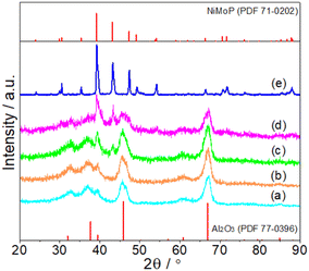 |
| | Fig. 1 XRD patterns of fresh (a) 0.62NiMoP, (b) 1.86NiMoP, (c) 4.40NiMoP, (d) 9.74NiMoP and (e) NiMoP (PDF file references are also included). | |
Subsequent XPS analysis was used to further confirm the formation of NiMoP on Al2O3. Fig. 2 shows the XPS spectra in the Mo 3d, Ni 2p and P 2p regions for the Al2O3-supported NiMoP samples. Since as-prepared phosphide samples were usually passivated prior to exposure to air, the surface regions should be dominated by oxidized species and underlying reduced species related to phosphide phases.23–25 In the case of 9.74NiMoP sample, the binding energy peaks of oxidized Mo (229.9 eV), Mo (232.8 eV), Ni (856.6 eV) and P (133.9 eV) were accordant with assignments by others to Mo4+, Mo6+, Ni2+ and P5+ species,25,26 respectively. And the binding energy peaks at 228.2, 853.3 and 129.5 eV were attributed to Moσ+ (Mo–P), Niδ+ (Ni–P) and Pα− (Mo(Ni)–P) species,27–29 respectively. The binding energy of Ni 2p3/2 at 853.3 eV was higher than that assigned to Ni0 (852.6 eV)30 but lower than that assigned to Ni2+ (856.6 eV). Clearly, the sequence of 0 < δ < 2 was accepted. In the case of 4.40NiMoP, 1.86NiMoP and 0.62NiMoP samples, it was reasonable that the intensities of Mo 3d, Ni 2p and P 2p levels would decrease with the decrease in Ni loading and even the peaks were too weak to be observed. Table 1 lists the BET surface area of the NiMoP samples obtained in this study. It was clear that the BET surface areas of the NiMoP/Al2O3 catalysts decreased monotonically with increase in Ni loading, and they were much higher than that of bulk NiMoP.
 |
| | Fig. 2 XPS spectra of Mo 3d, Ni 2p and P 2p (a) 0.62NiMoP, (b) 1.86NiMoP, (c) 4.40NiMoP and (d) 9.74NiMoP. | |
Table 1 BET surface area of the NiMoP catalysts obtained in this study
| Sample |
Ni loading (wt%) |
BET surface area (m2 g−1) |
| 0.62NiMoP |
0.62 |
198.5 |
| 1.86NiMoP |
1.86 |
190.9 |
| 4.40NiMoP |
4.40 |
153.8 |
| 9.74NiMoP |
9.74 |
127.5 |
| NiMoP |
— |
5.4 |
Fig. 3 shows the TEM images of 0.62NiMoP, 1.86NiMoP, 4.40NiMoP, 9.74NiMoP and NiMoP samples. In the case of the supported NiMoP samples, Fig. 3a–d showed the small and dispersed nanoparticles on Al2O3. In contrast, the unsupported NiMoP was composed of big size nanoparticles with serious conglomeration (see Fig. 3e). The insets clearly showed the (201) crystal plane of NiMoP, which proved the existence of NiMoP in the samples. The size distributions of the NiMoP nanoparticles determined by measuring particle size directly from TEM images can also be shown in these insets. It can be observed that the average particle size of supported NiMoP increased with the Ni loading. It was 8.6 nm in 0.62NiMoP, 9.1 nm in 1.86NiMoP, 10.8 nm in 4.40NiMoP and 12.3 nm in 9.74NiMoP, respectively. Note that the average particle sizes of the supported NiMoP were much smaller than that of unsupported one (150.2 nm). The results were in agreement with the results of BET (Table 1), because the decrease in agglomeration was usually responsible for the increase in the surface area of phosphide, as suggested before.31,32 In addition, the EDS-mapping images (Fig. S1†) confirmed the presence of Ni, Mo and P elements in the 1.86NiMoP, in agreement with the XPS results (Fig. 2).
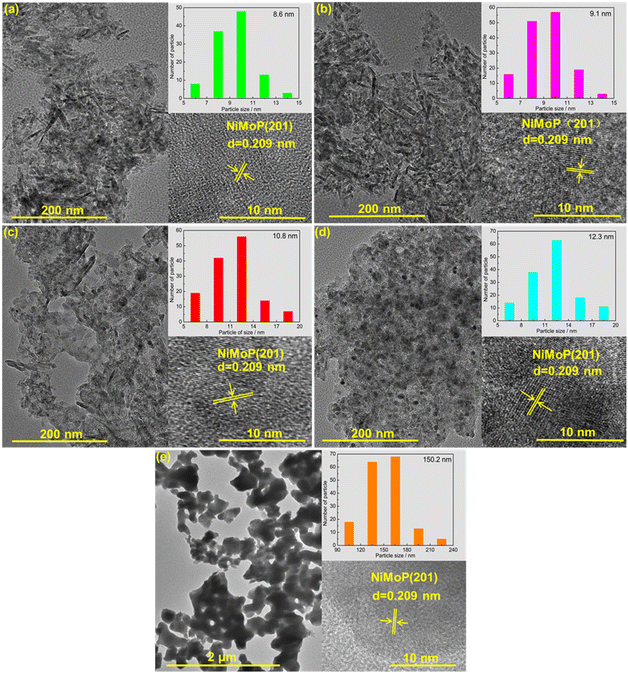 |
| | Fig. 3 TEM images of (a) 0.62NiMoP, (b) 1.86NiMoP, (c) 4.40NiMoP, (d) 9.74NiMoP and (e) NiMoP. The insets show the particle size distribution and crystal lattice of NiMoP. | |
It was believed that the interaction between particles and Al2O3 support was an important factor for the stabilizing of DRM catalysts.33,34 In order to give insights into the interaction between NiMoP and Al2O3, the reduction processes of oxide precursors were investigated by H2-TPR (see Fig. 4). As for the unsupported oxide precursor, the main reduction peak for the formation of NiMoP was observed at 660 °C. In the case of Al2O3-supported oxide precursors, the reduction temperatures shifted to a higher temperature region (665–710 °C) and they increased with the decrease in Ni loading. The results clearly indicated that there was an interaction between NiMoP and Al2O3, and the degree of interaction increased with the decrease in Ni loading.
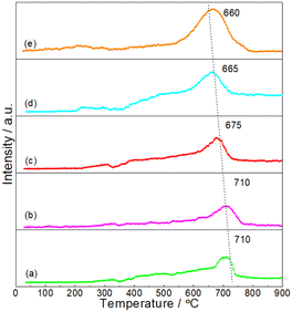 |
| | Fig. 4 H2-TPR profiles for the synthesis of (a) 0.62NiMoP, (b) 1.86NiMoP, (c) 4.40NiMoP, (d) 9.74NiMoP and (e) NiMoP from oxide precursors. | |
3.2 Catalytic performance
Fig. 5 shows the dependence of catalytic performance on temperature over these NiMoP catalysts. It was clear from Fig. 5 that compared to unsupported NiMoP catalyst, alumina-supported NiMoP catalysts showed higher activity for DRM at the entire reaction temperature range. Particularly, they were significantly more active at lower temperatures (≤800 °C). It was well known that the surface area and particle size were responsible for the catalytic performance of catalyst. The BET and TEM results (Table 1 and Fig. 3) indicated that the alumina-supported NiMoP catalysts can show much higher surface area and smaller particle size than unsupported NiMoP catalyst, which can account for their higher catalytic activity. Amongst this series of alumina-supported NiMoP catalysts, the 1.86NiMoP was found to exhibit the highest catalytic performance for DRM, which was probably attributed to its appropriate Ni loading and stronger interaction between NiMoP and Al2O3 suggested by H2-TPR (Fig. 4).
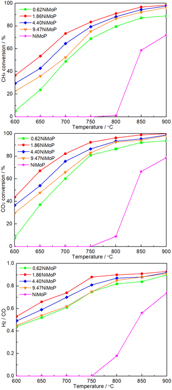 |
| | Fig. 5 Dependence of catalytic performance on temperature over 0.62NiMoP, 1.86NiMoP, 4.40NiMoP, 9.74NiMoP and NiMoP catalysts. Reaction conditions: CH4![[thin space (1/6-em)]](https://www.rsc.org/images/entities/char_2009.gif) : :![[thin space (1/6-em)]](https://www.rsc.org/images/entities/char_2009.gif) CO2 = 1 CO2 = 1![[thin space (1/6-em)]](https://www.rsc.org/images/entities/char_2009.gif) : :![[thin space (1/6-em)]](https://www.rsc.org/images/entities/char_2009.gif) 1, WHSV = 24 1, WHSV = 24![[thin space (1/6-em)]](https://www.rsc.org/images/entities/char_2009.gif) 000 cm3 g−1 h−1, reaction pressure = 1 atm, reaction time = 1 h. 000 cm3 g−1 h−1, reaction pressure = 1 atm, reaction time = 1 h. | |
Fig. 6 shows the time dependence of catalytic performance at a given temperature over 1.86NiMoP. It can be seen that the durability of 1.86NiMoP was strongly dependent on reaction temperature. At 650 °C, there was a rapid decline of performance within 3 h. The catalytic stability was slightly enhanced when the temperature was increased to 700 °C: the DRM performance decreased from XCH4 = 73%, XCH4XCO2 = 82%, and H2/CO = 0.74 to XCH4 = 40%, XCO2 = 42%, and H2/CO = 0.56 during 10 h. Note that at 750 °C the catalytic activity (XCH4 = 74% and XCO2 = 83%) was relatively stable through out the test period of 30 h. As proved by XPS (Fig. 2), the reduced Ni species in NiMoP/Al2O3 was considered to be Niδ+ (0 < δ < 2). For the sake of comparison, the DRM performance of NiMo/Al2O3 with Ni loading of 1.86 wt% (hereafter denoted as 1.86NiMo) was also investigated under similar reaction conditions (see Fig. S2†). Although the 1.86NiMo showed a slightly higher activity (XCH4 = 85% and XCO2 = 94%) than 1.86NiMoP (XCH4 = 84% and XCO2 = 92%) in the initial reaction period, the activity after 30 h for the former (XCH4 = 57% and XCO2 = 63%) was lower than that for the latter (XCH4 = 74% and XCO2 = 83%). In addition, the excellent performance of 1.86NiMoP showed great advantages over some literature reported Ni0 based catalysts with lower Ni loadings (see Table 2).
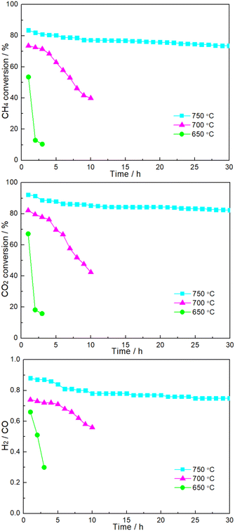 |
| | Fig. 6 Time dependence of catalytic performance over 1.86NiMoP catalyst at various reaction temperatures. Reaction conditions: CH4![[thin space (1/6-em)]](https://www.rsc.org/images/entities/char_2009.gif) : :![[thin space (1/6-em)]](https://www.rsc.org/images/entities/char_2009.gif) CO2 = 1 CO2 = 1![[thin space (1/6-em)]](https://www.rsc.org/images/entities/char_2009.gif) : :![[thin space (1/6-em)]](https://www.rsc.org/images/entities/char_2009.gif) 1, WHSV = 24 1, WHSV = 24![[thin space (1/6-em)]](https://www.rsc.org/images/entities/char_2009.gif) 000 cm3 g−1 h−1, reaction pressure = 1 atm. 000 cm3 g−1 h−1, reaction pressure = 1 atm. | |
Table 2 Comparison of CH4 conversion rate for the as-prepared and literature reported catalysts
| Catalyst |
Ni loading |
Temperature (°C) |
Feed composition |
WHSV (cm3 g−1 h−1) |
Time on stream (h) |
CH4 conversion rate (mol gcat−1 h−1) |
Ref. |
| 1 h |
20 h |
| 1.86NiMoP |
1.86 |
750 |
CH4![[thin space (1/6-em)]](https://www.rsc.org/images/entities/char_2009.gif) : :![[thin space (1/6-em)]](https://www.rsc.org/images/entities/char_2009.gif) CO2 = 1 CO2 = 1![[thin space (1/6-em)]](https://www.rsc.org/images/entities/char_2009.gif) : :![[thin space (1/6-em)]](https://www.rsc.org/images/entities/char_2009.gif) 1 1 |
24![[thin space (1/6-em)]](https://www.rsc.org/images/entities/char_2009.gif) 000 000 |
30 |
0.45 |
0.40 |
This work |
| 1.86NiMo |
1.86 |
750 |
CH4![[thin space (1/6-em)]](https://www.rsc.org/images/entities/char_2009.gif) : :![[thin space (1/6-em)]](https://www.rsc.org/images/entities/char_2009.gif) CO2 = 1 CO2 = 1![[thin space (1/6-em)]](https://www.rsc.org/images/entities/char_2009.gif) : :![[thin space (1/6-em)]](https://www.rsc.org/images/entities/char_2009.gif) 1 1 |
24![[thin space (1/6-em)]](https://www.rsc.org/images/entities/char_2009.gif) 000 000 |
30 |
0.46 |
0.37 |
| Ni/SBA-15 |
2 |
800 |
CH4![[thin space (1/6-em)]](https://www.rsc.org/images/entities/char_2009.gif) : :![[thin space (1/6-em)]](https://www.rsc.org/images/entities/char_2009.gif) CO2 CO2![[thin space (1/6-em)]](https://www.rsc.org/images/entities/char_2009.gif) : :![[thin space (1/6-em)]](https://www.rsc.org/images/entities/char_2009.gif) N2 = 1 N2 = 1![[thin space (1/6-em)]](https://www.rsc.org/images/entities/char_2009.gif) : :![[thin space (1/6-em)]](https://www.rsc.org/images/entities/char_2009.gif) 1 1![[thin space (1/6-em)]](https://www.rsc.org/images/entities/char_2009.gif) : :![[thin space (1/6-em)]](https://www.rsc.org/images/entities/char_2009.gif) 1 1 |
15![[thin space (1/6-em)]](https://www.rsc.org/images/entities/char_2009.gif) 000 000 |
24 |
0.17 |
0.14 |
33
|
| NiCo/CeZr |
1.2 |
750 |
CH4![[thin space (1/6-em)]](https://www.rsc.org/images/entities/char_2009.gif) : :![[thin space (1/6-em)]](https://www.rsc.org/images/entities/char_2009.gif) CO2 = 1 CO2 = 1![[thin space (1/6-em)]](https://www.rsc.org/images/entities/char_2009.gif) : :![[thin space (1/6-em)]](https://www.rsc.org/images/entities/char_2009.gif) 1 1 |
12![[thin space (1/6-em)]](https://www.rsc.org/images/entities/char_2009.gif) 000 000 |
20 |
0.19 |
0.19 |
34
|
| NiCe/HAP |
2 |
750 |
CH4![[thin space (1/6-em)]](https://www.rsc.org/images/entities/char_2009.gif) : :![[thin space (1/6-em)]](https://www.rsc.org/images/entities/char_2009.gif) CO2 CO2![[thin space (1/6-em)]](https://www.rsc.org/images/entities/char_2009.gif) : :![[thin space (1/6-em)]](https://www.rsc.org/images/entities/char_2009.gif) He = 1 He = 1![[thin space (1/6-em)]](https://www.rsc.org/images/entities/char_2009.gif) : :![[thin space (1/6-em)]](https://www.rsc.org/images/entities/char_2009.gif) 1 1![[thin space (1/6-em)]](https://www.rsc.org/images/entities/char_2009.gif) : :![[thin space (1/6-em)]](https://www.rsc.org/images/entities/char_2009.gif) 3 3 |
60![[thin space (1/6-em)]](https://www.rsc.org/images/entities/char_2009.gif) 000 000 |
110 |
0.47 |
0.45 |
35
|
| NiCo/HAP |
2.4 |
750 |
CH4![[thin space (1/6-em)]](https://www.rsc.org/images/entities/char_2009.gif) : :![[thin space (1/6-em)]](https://www.rsc.org/images/entities/char_2009.gif) CO2 CO2![[thin space (1/6-em)]](https://www.rsc.org/images/entities/char_2009.gif) : :![[thin space (1/6-em)]](https://www.rsc.org/images/entities/char_2009.gif) Ar = 2 Ar = 2![[thin space (1/6-em)]](https://www.rsc.org/images/entities/char_2009.gif) : :![[thin space (1/6-em)]](https://www.rsc.org/images/entities/char_2009.gif) 2 2![[thin space (1/6-em)]](https://www.rsc.org/images/entities/char_2009.gif) : :![[thin space (1/6-em)]](https://www.rsc.org/images/entities/char_2009.gif) 5 5 |
15![[thin space (1/6-em)]](https://www.rsc.org/images/entities/char_2009.gif) 882 882 |
160 |
0.13 |
0.12 |
36
|
| Ni/DFSBA-15 |
3 |
800 |
CH4![[thin space (1/6-em)]](https://www.rsc.org/images/entities/char_2009.gif) : :![[thin space (1/6-em)]](https://www.rsc.org/images/entities/char_2009.gif) CO2 = 1 CO2 = 1![[thin space (1/6-em)]](https://www.rsc.org/images/entities/char_2009.gif) : :![[thin space (1/6-em)]](https://www.rsc.org/images/entities/char_2009.gif) 1 1 |
15![[thin space (1/6-em)]](https://www.rsc.org/images/entities/char_2009.gif) 000 000 |
30 |
0.28 |
0.25 |
37
|
3.3 Characterizations of used NiMoP catalysts
In this study, the used 1.86NiMoP catalysts functioned in DRM at different temperatures (650, 700 and 750 °C) were hereafter denoted as 1.86NiMoP-T (T = 650, 700 and 800). Fig. S3† shows the XPS spectra of Mo 3d, Ni 2p and P 2p for the 1.86NiMoP-650, 1.86NiMoP-700 and 1.86NiMoP-750 samples. On the basis of curve fitting, the Mo 3d5/2, Ni 2p3/2 and P 2p3/2 binding energies and the distribution of these corresponding species as well as the contents of Moσ+ and Niδ+ are listed in Table 3. For the sake of comparison, the XPS results for fresh 1.86NiMoP from Fig. 2 are also included. Compared with 1.86NiMoP sample, the 1.86NiMoP-650 and 1.86NiMoP-700 samples showed two Mo species (Mo4+ and Mo6+) and one Ni species (Ni2+) but no Moσ+ and Niδ+. This was probably because the Moσ+ and Niδ+ species were so low in concentration that their corresponding peak areas were overshadowed by Mo4+ and Ni2+, respectively. However, the Moσ+ and Niδ+ contents (12.9 and 14.1%) for 1.86NiMoP-750 sample were very close to those (13.1 and 13.8%) for 1.86NiMoP sample. The results indicated that the 1.86NiMoP catalyst can remain its surface structure relatively stable at 750 °C in DRM but it suffered from surface oxidation at lower temperatures (650 and 700 °C).
Table 3 XPS results for fresh and used NiMoP catalysts
| Sample |
Binding energy (eV) |
Moσ+ content (%) |
Niδ+ content (%) |
| Mo 3d5/2 |
Ni 2p3/2 |
P 2p3/2 |
| Moσ+ (Mo–P) |
Mo4+ (Mo–O) |
Mo6+ (Mo–O) |
Niδ+ (Ni–P) |
Ni2+ (Ni–O) |
Pα− (Mo(Ni)–P) |
P5+ (P–O) |
| Moσ+ content = Moσ+/(Moσ+ + Mo4+ + Mo6+); Niδ+ content = Niδ+/(Niδ+ + Ni2+). |
| 1.86NiMoP |
228.4 |
229.9 |
232.7 |
853.3 |
856.4 |
N/A |
133.7 |
13.1 |
13.8 |
| 1.86NiMoP-650 |
N/A |
229.9 |
232.6 |
N/A |
856.1 |
N/A |
133.9 |
0 |
0 |
| 1.86NiMoP-700 |
N/A |
229.9 |
232.6 |
N/A |
856.1 |
N/A |
133.9 |
0 |
0 |
| 1.86NiMoP-750 |
228.3 |
229.8 |
232.8 |
853.1 |
856.6 |
N/A |
134.0 |
12.9 |
14.1 |
In order to quantify the carbon deposition on the catalyst surfaces, the 1.86NiMoP-650, 1.86NiMoP-700 and 1.86NiMoP-750 samples were characterized by TGA (see Fig. 7). It had been widely accepted that the weight loss at the lower temperature (below 400 °C) was due to thermal desorption of H2O and removal of easily oxidizable amorphous carbon species.38,39 And the weight loss at the higher temperature (400–750 °C) was fully attributable to carbon combustion.40,41 By comparing the TGA curve of fresh catalyst with used catalysts, the weight loss below 400 °C was mainly due to thermal desorption of H2O on the surface and inside catalyst. The weight losses of 1.86NiMoP-650, 1.86NiMoP-700 and 1.86NiMoP-750 in the high temperature range were 1.3, 2.6 and 2.3%, respectively. Correspondingly, their carbon deposition rates estimated by TGA were 4.3, 2.6 and 0.8 mg gcat−1 h−1, respectively, indicating that the low reaction temperature was more favourable to the formation of carbon deposition. Correlating the XPS and TGA results with catalytic stability data, it can be deduced that the rapid deactivation of 1.86NiMoP at 650 and 700 °C should be attributed to both surface oxidation and carbon deposition.
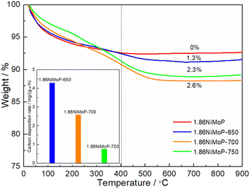 |
| | Fig. 7 TGA curves of 1.86NiMoP, 1.86NiMoP-650, 1.86NiMoP-700 and 1.86NiMoP-750 samples. The inset shows their carbon deposition rates in DRM. | |
3.4 CH4 and CO2 dissociations
It was well known that the DRM reaction mechanism on phosphide catalysts can be proposed as two competing mechanisms (noble metal type mechanism and oxidation–reduction type mechanism).25 The noble metal type mechanism can be represented as:| | | C(♦) + O(♦) → CO + 2(♦), | (3) |
where (♦) represented a vacancy near the surface of the phosphide. The oxidation–reduction cycle for phosphides (e.g. MoP) usually included two reactions, viz. oxidation reaction (CO2 dissociation, reaction (4)) and carbothermal reduction reaction (reactions (5)):42–45| | | (x + y)CO2 + MoP → MoOx + POy + (x + y)CO, | (4) |
| | | MoOx + POy + (x + y)C → MoP + (x + y)CO | (5) |
The coke formed was mainly considered in CH4 cracking reaction (reaction (1)) because the rate of Boudouard reaction (2CO → C + CO2) was much lower than that of CH4 cracking reaction when the temperature was above 650 °C.46 It was suggested that the matching between CH4 dissociation rate and CO2 dissociation rate was the first condition for maintaining the oxidation–reduction cycle.19,20,42–45 If the CO2 dissociation was more favorable, the phosphides would suffer from oxidation. Conversely, the excessive dissociation of CH4 would facilitate the formation of coke. As shown in Fig. 8, it was clear that the RCH4 was higher than RCO2 on the 1.86NiMoP catalyst in the whole temperature range from 650 to 850 °C, which suggested that coking on the catalyst was unavoidable in DRM. In addition, the RCH4/RCO2 ratio was found to decrease linearly with the temperature. This suggested that the carbon deposition rate was also increased with temperature. The result was in good agreement with the result of TGA (Fig. 7). Interestingly, the 1.86NiMoP suffered not only from carbon deposition but also from surface oxidation in DRM at 650 and 700 °C (see Table 3). Indeed, it was possible that phosphides/carbides would simultaneously undergo carbon deposition and surface oxidation during DRM.19,47 This was probably because high-temperature sintering of catalyst can result in the segregation of the active sites for CO2 dissociation and CH4 dissociation, which hindered the process of reaction (5). In other words, the reaction between carbon species and oxidized species viareaction (5) can not be completed quickly enough, which was the main reason for the coexistence of coking and oxidation of catalyst. Therefore, the second condition mentioned before for maintaining the oxidation–reduction cycle was that the active sites for CO2 dissociation and CH4 dissociation over phosphides must locate very close to each other.19 However, it was found that the catalytic stability of 1.86NiMoP was greatly enhanced by increasing temperature from 650 to 750 °C (Fig. 6). Thus, the current coexistence of coking and oxidation of catalyst after DRM might not be due to high-temperature sintering. In view of the fact that the catalytic stability was greatly dependent on temperature, it was reasonable to deduce that a high enough temperature was essential for a fast achievement of reaction (5). The H2-TPR result (Fig. 4) clearly indicated the oxidized species on the 1.86NiMoP surface can not be reduced completely until 710 °C. It was suggested that the carbon species can not react quickly with the oxidized species at 650 and 700 °C, leading to catalyst oxidation and coking at the same time. When the reaction temperature was at 750 °C, the rate for reaction (5) was enhanced and the oxidation–reduction cycle can be well established. This was the reason why the lifetime of 1.86NiMoP can be greatly extended in DRM at 750 °C. Therefore, we proposed that choosing an appropriate reaction temperature that can simultaneously remove surface oxygen and carbon species was another condition for maintaining the oxidation–reduction cycle in DRM.
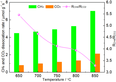 |
| | Fig. 8 CH4 conversion rate (RCH4), CO2 conversion rate (RCO2) and RCH4/RCO2 over 1.86NiMoP at different temperatures. Reaction conditions: CH4![[thin space (1/6-em)]](https://www.rsc.org/images/entities/char_2009.gif) : :![[thin space (1/6-em)]](https://www.rsc.org/images/entities/char_2009.gif) Ar = 1 Ar = 1![[thin space (1/6-em)]](https://www.rsc.org/images/entities/char_2009.gif) : :![[thin space (1/6-em)]](https://www.rsc.org/images/entities/char_2009.gif) 49, CO2 49, CO2![[thin space (1/6-em)]](https://www.rsc.org/images/entities/char_2009.gif) : :![[thin space (1/6-em)]](https://www.rsc.org/images/entities/char_2009.gif) Ar = 1 Ar = 1![[thin space (1/6-em)]](https://www.rsc.org/images/entities/char_2009.gif) : :![[thin space (1/6-em)]](https://www.rsc.org/images/entities/char_2009.gif) 49, WHSV = 30 49, WHSV = 30![[thin space (1/6-em)]](https://www.rsc.org/images/entities/char_2009.gif) 000 cm3 g−1 h−1, reaction time = 10 min. 000 cm3 g−1 h−1, reaction time = 10 min. | |
Conclusions
A series of Al2O3-supported NiMoP phosphides with 0.62–9.47 wt% Ni loadings were synthesized and used as catalysts for DRM. These supported NiMoP catalysts showed much higher performance than unsupported one, more particularly at low temperatures (600–800 °C), which might be attributed to their optimal microstructures (high surface area and small particle size) and strong interaction between NiMoP and Al2O3. Note that the active Ni species in the NiMoP/Al2O3 was regarded as Niδ+ (0 < δ < 2), which can show more stable DRM activity than the Ni0 in NiMo/Al2O3 and some literature reported Ni-based catalyst systems. It was found that a high enough temperature was essential for maintaining the oxidation–reduction cycle over phosphides in DRM. Therefore, besides the two conditions: matching between the dissociation rates of CH4 and CO2 and keeping a close contact of active sites for the two reactants, choosing an appropriate reaction temperature that can simultaneously remove surface oxygen and carbon species was proposed to be another condition for maintaining the oxidation–reduction cycle of phosphides in DRM.
Conflicts of interest
There are no conflicts to declare.
Acknowledgements
The work was supported by the National Natural Science Foundation of China (No. 21978125), the Liaoning Revitalization Talents Program (No. XLYC1907003), the Fushun Revitalization Talents Program (No. FSYC202101001), the Project of Liaoning Province Department of Education (No. LJKZ0376) and Liaoning BaiQianWan Talents Program.
Notes and references
- K. Huang, J. B. Miller, G. W. Huber, J. A. Dumesic and C. T. Maravelias, Joule, 2018, 2, 349–365 CrossRef CAS.
- M. Yu, Y.-A. Zhu, Y. Lu, G. Tong, K. Zhu and X. Zhou, Appl. Catal., B, 2015, 165, 43–56 CrossRef CAS.
- M. Usman, W. M. A. Wan Daud and H. F. Abbas, Renewable Sustainable Energy Rev., 2015, 45, 710–744 CrossRef CAS.
- A. Abdulrasheed, A. A. Jalil, Y. Gambo, M. Ibrahim, H. U. Hambali and M. Y. Shahul Hamid, Renewable Sustainable Energy Rev., 2019, 108, 175–193 CrossRef CAS.
- S. Arora and R. Prasad, RSC Adv., 2016, 6, 108668–108688 RSC.
- K. Bu, J. Deng, X. Zhang, S. Kuboon, T. Yan, H. Li, L. Shi and D. Zhang, Appl. Catal., B, 2020, 267, 118692 CrossRef.
- Y. Turap, I. Wang, T. Fu, Y. Wu, Y. Wang and W. Wang, Int. J. Hydrogen Energy, 2020, 45, 6538–6548 CrossRef.
- A. S. Al-Fatesh, R. Kumar, A. H. Fakeeha, S. O. Kasim, J. Khatri, A. A. Ibrahim, R. Arasheed, M. Alabdulsalam, M. S. Lanre, A. I. Osman, A. E. Abasaeed and A. Bagabas, Sci. Rep., 2020, 10, 13861 CrossRef PubMed.
- N. Abdullah, N. Ainirazali, C. C. Chong, H. A. Razak, H. D. Setiabudi, S. Y. Chin and A. A. Jalil, Int. J. Hydrogen Energy, 2020, 45, 18411–18425 CrossRef.
- F. Rahbar Shamskar, F. Meshkani and M. Rezaei, J. CO2 Util., 2017, 22, 124–134 CrossRef.
- A. S. Al-Fatesh, R. Kumar, S. O. Kasim, A. A. Ibrahim, A. H. Fakeeha, A. E. Abasaeed, R. Alrasheed, A. Bagabas, M. L. Chaudhary, F. Frusteri and B. Chowdhury, Catal. Today, 2020, 348, 236–242 CrossRef CAS.
- J. Ashok and S. Kawi, Int. J. Hydrogen Energy, 2013, 38, 13938–13949 CrossRef CAS.
- Z. Alipour, M. Rezaei and F. Meshkani, J. Energy Chem., 2014, 23, 633–638 CrossRef.
- Z. Alipour, M. Rezaei and F. Meshkani, Fuel, 2014, 129, 197–203 CrossRef CAS.
- R. Yang, C. Xing, C. Lv, L. Shi and N. Tsubaki, Appl. Catal., A, 2010, 385, 92–100 CrossRef CAS.
- D. Zambrano, J. Soler, J. Herguido and M. Menéndez, Top. Catal., 2019, 62, 456–466 CrossRef CAS.
- X. Li, S. Li, Y. Yang, M. Wu and F. He, Catal. Lett., 2007, 118, 59–63 CrossRef CAS.
- Z. Li, Q. Liu, Y. Shi, Z. Yao, W. Ding and Y. Sun, Dalton Trans., 2019, 48, 14256–14260 RSC.
- W. Wu, Q. Liu, Y. Shi, Z. Yao, W. Ding and B. Dou, React. Chem. Eng., 2020, 5, 719–727 RSC.
- X. Chen, W. Ding, Z. Yao, S. Na, Z. Wang, S. Yan and L. Wang, Catal. Sci. Technol., 2021, 11, 6654–6658 RSC.
- M. González-Castaño, E. le Saché, C. Berry, L. Pastor-Pérez, H. Arellano-García, Q. Wang and T. Reina, Catalysts, 2021, 11, 446 CrossRef.
- Y. Shi, S. Wang, Y. Li, F. Yang, H. Yu, Y. Chu, T. Li and H. Yin, Materials, 2022, 15, 3044 CrossRef.
- A. W. Burns, A. F. Gaudette and M. E. Bussell, J. Catal., 2008, 260, 262–269 CrossRef.
- Z. Yao, M. Li, X. Wang, X. Qiao, J. Zhu, Y. Zhao, G. Wang, J. Yin and H. Wang, Dalton Trans., 2015, 44, 5503–5509 RSC.
- Z. Yao, F. Luan, Y. Sun, B. Jiang, J. Song and H. Wang, Catal. Sci. Technol., 2016, 6, 7996–8004 RSC.
- I. Abu and K. Smith, J. Catal., 2006, 241, 356–366 CrossRef.
- X. Qi, X. Liu, J. Li, H. Qu, Y. Su and H. Su, Plasma Sci. Technol., 2020, 22, 105502 CrossRef.
- C. Cheng, S. S. A. Shah, T. Najam, X. Qi and Z. Wei, Electrochim. Acta, 2018, 260, 358–364 CrossRef.
- L. Wang, Z. Li, P. Zhang, G. Wang and G. Xie, Int. J. Hydrogen Energy, 2016, 41, 1468–1476 CrossRef.
- M. C. Biesinger, B. P. Payne, L. W. M. Lau, A. Gerson and R. S. C. Smart, Surf. Interface Anal., 2009, 41, 324–332 CrossRef.
- Z. Yao, G. Wang, Y. Shi, Y. Zhao, J. Jiang, Y. Zhang and H. Wang, Dalton Trans., 2015, 44, 14122–14129 RSC.
- R. Cheng, Y. Shu, L. Li, M. Zheng, X. Wang, A. Wang and T. Zhang, Appl. Catal., A, 2007, 316, 160–168 CrossRef.
- K. Li, C. L. Pei, X. Y. Li, S. Chen, X. H. Zhang, R. Liu and J. L. Gong, Appl. Catal., B, 2020, 264, 118448 CrossRef.
- R. Yang, C. Xing, C. Lv, L. Shi and N. Tsubaki, Appl. Catal., A, 2010, 385, 92–100 CrossRef.
- N. Abdullah, N. Ainirazali, C. C. Chong, H. A. Razak, H. D. Setiabudi, S. Y. Chin and A. A. Jalil, Int. J. Hydrogen Energy, 2020, 45, 18411–18425 CrossRef.
- M. S. Aw, I. G. Osojnik Črnivec and A. Pintar, Catal. Sci. Technol., 2014, 4, 1340–1349 RSC.
- M. Akri, S. Zhao, X. Li, K. Zang, A. F. Lee, M. A. Isaacs, W. Xi, Y. Gangarajula, J. Luo, Y. Ren, Y. T. Cui, L. Li, Y. Su, X. Pan, W. Wen, Y. Pan, K. Wilson, L. Li, B. Qiao, H. Ishii, Y. F. Liao, A. Wang, X. Wang and T. Zhang, Nat. Commun., 2019, 10, 5181 CrossRef PubMed.
- S. J. Hassani Rad, M. Haghighi, A. A. Eslami, F. Rahmani and N. Rahemi, Int. J. Hydrogen Energy, 2016, 41, 5335–5350 CrossRef CAS.
- N. Rahemi, M. Haghighi, A. A. Babaluo, M. F. Jafari and S. Allahyari, Korean J. Chem. Eng., 2014, 31, 1553–1563 CrossRef CAS.
- R. Razzaq, C. Li, M. Usman, K. Suzuki and S. Zhang, Chem. Eng. J., 2015, 262, 1090–1098 CrossRef CAS.
- Y. Zhan, J. Han, Z. Bao, B. Cao, Y. Li, J. Street and F. Yu, Mol. Catal., 2017, 436, 248–258 CrossRef CAS.
- Y. Cui, Q. Liu, Z. Yao, B. Dou, Y. Shi and Y. Sun, Int. J. Hydrogen Energy, 2019, 44, 11441–11447 CrossRef CAS.
- Z. Yao, F. Luan, Y. Sun, B. Jiang, J. Song and H. Wang, Catal. Sci. Technol., 2016, 6, 7996–8004 RSC.
- G. Sun, Y. Yang, Z. W. Yao, Y. Shi and W. Mao, Catal. Sci. Technol., 2021, 11, 3818–3825 RSC.
- W. Zhang, W. Ding, Z. Yao, Y. Shi, Y. Sun and X. Kang, Phosphorus, Sulfur Silicon Relat. Elem., 2021, 196, 826–831 CrossRef CAS.
- H. Hu, W. Ding, G. Sun and Z. Yao, Appl. Surf. Sci., 2022, 606, 154802 CrossRef CAS.
- C. Shi, A. Zhang, X. Li, S. Zhang, A. Zhu, Y. Ma and C. Au, Appl. Catal., A, 2012, 431–432, 164–170 CrossRef CAS.
|
| This journal is © The Royal Society of Chemistry 2023 |
Click here to see how this site uses Cookies. View our privacy policy here.  *
*
![[thin space (1/6-em)]](https://www.rsc.org/images/entities/char_2009.gif) :
:![[thin space (1/6-em)]](https://www.rsc.org/images/entities/char_2009.gif) Mo = 1
Mo = 1![[thin space (1/6-em)]](https://www.rsc.org/images/entities/char_2009.gif) :
:![[thin space (1/6-em)]](https://www.rsc.org/images/entities/char_2009.gif) 1 were prepared by the incipient wetness method via stirring γ-Al2O3 in aqueous solutions of (NH4)6Mo7O24·4H2O and Ni(CH3COO)2·4H2O. The Ni concentration was regulated for a Ni loading of 0.62–9.74 wt%, respectively. The resulting precursors were dried at 110 °C for 12 h and calcined at 500 °C for 3 h. The alumina-supported NiMoP phosphide catalysts were prepared from alumina-supported oxide precursors via H2 reduction method. The precursor was heated in a quartz reactor under a flow of pure H2 (150 ml min−1). The temperature was increased from room temperature (RT) to 300 °C at a rate of 10 °C min−1 followed by a rise in temperature from 300 to 850 °C at a rate of 1 °C min−1 and then kept at the temperature for 1 h before cooling to RT in a H2 flow. Finally, the material was passivated in 1%O2/Ar for 12 h before it was exposed to air. An unsupported NiMoP catalyst was also prepared by the same method and procedure mentioned above. The obtained alumina-supported NiMoP phosphide catalysts with Ni loadings of 0.62, 1.86, 4.40 and 9.74 wt% were designated as xNiMoP (x = 0.62, 1.86, 4.40 and 9.74). And the unsupported NiMoP catalyst was denoted as NiMoP.
1 were prepared by the incipient wetness method via stirring γ-Al2O3 in aqueous solutions of (NH4)6Mo7O24·4H2O and Ni(CH3COO)2·4H2O. The Ni concentration was regulated for a Ni loading of 0.62–9.74 wt%, respectively. The resulting precursors were dried at 110 °C for 12 h and calcined at 500 °C for 3 h. The alumina-supported NiMoP phosphide catalysts were prepared from alumina-supported oxide precursors via H2 reduction method. The precursor was heated in a quartz reactor under a flow of pure H2 (150 ml min−1). The temperature was increased from room temperature (RT) to 300 °C at a rate of 10 °C min−1 followed by a rise in temperature from 300 to 850 °C at a rate of 1 °C min−1 and then kept at the temperature for 1 h before cooling to RT in a H2 flow. Finally, the material was passivated in 1%O2/Ar for 12 h before it was exposed to air. An unsupported NiMoP catalyst was also prepared by the same method and procedure mentioned above. The obtained alumina-supported NiMoP phosphide catalysts with Ni loadings of 0.62, 1.86, 4.40 and 9.74 wt% were designated as xNiMoP (x = 0.62, 1.86, 4.40 and 9.74). And the unsupported NiMoP catalyst was denoted as NiMoP.
![[thin space (1/6-em)]](https://www.rsc.org/images/entities/char_2009.gif) :
:![[thin space (1/6-em)]](https://www.rsc.org/images/entities/char_2009.gif) CO2 = 1
CO2 = 1![[thin space (1/6-em)]](https://www.rsc.org/images/entities/char_2009.gif) :
:![[thin space (1/6-em)]](https://www.rsc.org/images/entities/char_2009.gif) 1) was allowed to pass through the catalyst (60–80 meshes) with a WHSV of 24
1) was allowed to pass through the catalyst (60–80 meshes) with a WHSV of 24![[thin space (1/6-em)]](https://www.rsc.org/images/entities/char_2009.gif) 000 cm3 g−1 h−1. The gas-phase products were analyzed by on-line GC. The conversions of CH4 and CO2, and H2/CO were defined as follows (ni,in = the initial molar fraction of component i in the feed, ni,out = the final molar fraction of component i in the gaseous effluent):
000 cm3 g−1 h−1. The gas-phase products were analyzed by on-line GC. The conversions of CH4 and CO2, and H2/CO were defined as follows (ni,in = the initial molar fraction of component i in the feed, ni,out = the final molar fraction of component i in the gaseous effluent):


![[thin space (1/6-em)]](https://www.rsc.org/images/entities/char_2009.gif) :
:![[thin space (1/6-em)]](https://www.rsc.org/images/entities/char_2009.gif) CO2 = 1
CO2 = 1![[thin space (1/6-em)]](https://www.rsc.org/images/entities/char_2009.gif) :
:![[thin space (1/6-em)]](https://www.rsc.org/images/entities/char_2009.gif) 1, WHSV = 24
1, WHSV = 24![[thin space (1/6-em)]](https://www.rsc.org/images/entities/char_2009.gif) 000 cm3 g−1 h−1, reaction pressure = 1 atm.
000 cm3 g−1 h−1, reaction pressure = 1 atm.![[thin space (1/6-em)]](https://www.rsc.org/images/entities/char_2009.gif) :
:![[thin space (1/6-em)]](https://www.rsc.org/images/entities/char_2009.gif) CO2 = 1
CO2 = 1![[thin space (1/6-em)]](https://www.rsc.org/images/entities/char_2009.gif) :
:![[thin space (1/6-em)]](https://www.rsc.org/images/entities/char_2009.gif) 1
1![[thin space (1/6-em)]](https://www.rsc.org/images/entities/char_2009.gif) 000
000![[thin space (1/6-em)]](https://www.rsc.org/images/entities/char_2009.gif) :
:![[thin space (1/6-em)]](https://www.rsc.org/images/entities/char_2009.gif) CO2
CO2![[thin space (1/6-em)]](https://www.rsc.org/images/entities/char_2009.gif) :
:![[thin space (1/6-em)]](https://www.rsc.org/images/entities/char_2009.gif) N2 = 1
N2 = 1![[thin space (1/6-em)]](https://www.rsc.org/images/entities/char_2009.gif) :
:![[thin space (1/6-em)]](https://www.rsc.org/images/entities/char_2009.gif) 1
1![[thin space (1/6-em)]](https://www.rsc.org/images/entities/char_2009.gif) :
:![[thin space (1/6-em)]](https://www.rsc.org/images/entities/char_2009.gif) 1
1![[thin space (1/6-em)]](https://www.rsc.org/images/entities/char_2009.gif) 000
000![[thin space (1/6-em)]](https://www.rsc.org/images/entities/char_2009.gif) :
:![[thin space (1/6-em)]](https://www.rsc.org/images/entities/char_2009.gif) CO2 = 1
CO2 = 1![[thin space (1/6-em)]](https://www.rsc.org/images/entities/char_2009.gif) :
:![[thin space (1/6-em)]](https://www.rsc.org/images/entities/char_2009.gif) 1
1![[thin space (1/6-em)]](https://www.rsc.org/images/entities/char_2009.gif) 000
000![[thin space (1/6-em)]](https://www.rsc.org/images/entities/char_2009.gif) :
:![[thin space (1/6-em)]](https://www.rsc.org/images/entities/char_2009.gif) CO2
CO2![[thin space (1/6-em)]](https://www.rsc.org/images/entities/char_2009.gif) :
:![[thin space (1/6-em)]](https://www.rsc.org/images/entities/char_2009.gif) He = 1
He = 1![[thin space (1/6-em)]](https://www.rsc.org/images/entities/char_2009.gif) :
:![[thin space (1/6-em)]](https://www.rsc.org/images/entities/char_2009.gif) 1
1![[thin space (1/6-em)]](https://www.rsc.org/images/entities/char_2009.gif) :
:![[thin space (1/6-em)]](https://www.rsc.org/images/entities/char_2009.gif) 3
3![[thin space (1/6-em)]](https://www.rsc.org/images/entities/char_2009.gif) 000
000![[thin space (1/6-em)]](https://www.rsc.org/images/entities/char_2009.gif) :
:![[thin space (1/6-em)]](https://www.rsc.org/images/entities/char_2009.gif) CO2
CO2![[thin space (1/6-em)]](https://www.rsc.org/images/entities/char_2009.gif) :
:![[thin space (1/6-em)]](https://www.rsc.org/images/entities/char_2009.gif) Ar = 2
Ar = 2![[thin space (1/6-em)]](https://www.rsc.org/images/entities/char_2009.gif) :
:![[thin space (1/6-em)]](https://www.rsc.org/images/entities/char_2009.gif) 2
2![[thin space (1/6-em)]](https://www.rsc.org/images/entities/char_2009.gif) :
:![[thin space (1/6-em)]](https://www.rsc.org/images/entities/char_2009.gif) 5
5![[thin space (1/6-em)]](https://www.rsc.org/images/entities/char_2009.gif) 882
882![[thin space (1/6-em)]](https://www.rsc.org/images/entities/char_2009.gif) :
:![[thin space (1/6-em)]](https://www.rsc.org/images/entities/char_2009.gif) CO2 = 1
CO2 = 1![[thin space (1/6-em)]](https://www.rsc.org/images/entities/char_2009.gif) :
:![[thin space (1/6-em)]](https://www.rsc.org/images/entities/char_2009.gif) 1
1![[thin space (1/6-em)]](https://www.rsc.org/images/entities/char_2009.gif) 000
000


