 Open Access Article
Digitisation of a modular plug and play 3D printed continuous flow system for chemical synthesis†
Mireia Benito
Montaner
 ,
Matthew R.
Penny
 and
Stephen T.
Hilton
 *
*
UCL School of Pharmacy, 29-39 Brunswick Square, London WC1N 1AX, UK. E-mail: s.hilton@ucl.ac.uk
First published on 3rd October 2023
Abstract
We describe the development of a digital modular 3D printed continuous flow system to carry out both classical and photochemical synthesis that uses a novel PC based software interface for communication. Using this system, we describe how we were able to both control and monitor reaction conditions at the same time. The system integrates in-line sensors via a simple cassette based system that is analogous to a retro-games console enabling hot-swapping of modules by a user. A PC-interface platform was created to automate both its functional control, including the injection of solvents, and the visualization of sensor-reported data. The utility of the system was demonstrated by performing a series of reactions highlighting the importance that precise control of solvent flow rate and accurate reporting of reaction temperatures can have on standardization and reproducibility and that the system can be easily modified to allow for scale-up synthesis.
Introduction
Despite the numerous advantages of continuous flow over batch chemical syntheses, batch processes remain, in general, a standard “go-to” option for new Active Pharmaceutical Ingredients (APIs) syntheses for most chemists. Notwithstanding the advantages of continuous flow, chemists often reach for batch processes due to their prior training and familiarity with the associated set-up and procedures as well as the availability of the requisite equipment needed to carry out a reaction. This problem arises from a deficit of continuous flow experimental training at University level and a lack of continuous flow equipment in most laboratories due to the high costs of the commercial systems.1 The cost of flow systems can vary significantly based on the specific modules and advanced features required. In some cases, the price can exceed tens of thousands of pounds, rendering them unaffordable for a considerable number of researchers. In order to make flow chemistry more accessible and to increase the availability of flow systems, researchers have sought to design and develop 3D printed continuous flow systems as well as alternative low-cost syringe pumps with a number of recent reports in the literature.2,3Adaptations of existing continuous flow equipment to address these deficits and reduce costs have utilised 3D printed polypropylene (PP) column reactors in the synthesis of bicyclic heterocycles and complex tetracycles,4 or the use of stainless-steel flow reactors by Maier as examples.5 Notable efforts in the development of integrated digital continuous flow systems by others have focussed on 3D printed syringe pumps and continuous flow systems as reported by Saggiomo, Cronin and Neumaier amongst others.6 Alongside the growing popularity of the maker culture exemplified by 3D printing which has heavily impacted the field of chemistry and has reduced these deficits and improved access to continuous flow equipment, the use of open-source software has also been rapidly incorporated and reported within the scientific community in the development of low-cost instrumentation.
Through open-source electronics, such as Arduino microcontrollers, chemistry researchers have become more digitally oriented, resulting in improved reporting and acquisition, as well as automation and remote collection of research data. Furthermore, the use of open-source software combined with 3D printed equipment has allowed scientists to realise the development of low-cost laboratory systems tailored to meet researcher's needs, thus circumventing the limitations of commercial laboratory equipment, whose functionalities and properties cannot normally be modified. A recent overview of the various types of microcontrollers used in the scientific field has been described by Prabhu and Urban and there have been a number of recent articles demonstrating how low-cost electronics can be integrated with chemical synthesis and continuous flow synthesis for substance detection.7–20
System design
As a result of experiencing the high costs of continuous flow systems along with prior 3D printing research, in 2019, the Hilton group designed and introduced a low-cost 3D-printed modular pressure driven continuous flow system that chemists could use and integrate with existing laboratory equipment (Fig. 1A).21,22 Whilst the system was designed to meet the entry needs of a continuous flow system similar to commercially available congeners, it lacked the ability to monitor reaction parameters in real time, which is essential if chemists are to enhance reproducibility and standardisation of reaction conditions in the literature. In order to address these deficits and to provide a standardised system for reporting continuous flow data, we now wish to describe our research into a modular digitized version of our previous 3D printed system that now incorporates Arduino open-source electronics and a simple-to-use PC linked software interface to accurately monitor the temperature or flow rate throughout a reaction and that allows for facile variable scalable syntheses (Fig. 1B and C).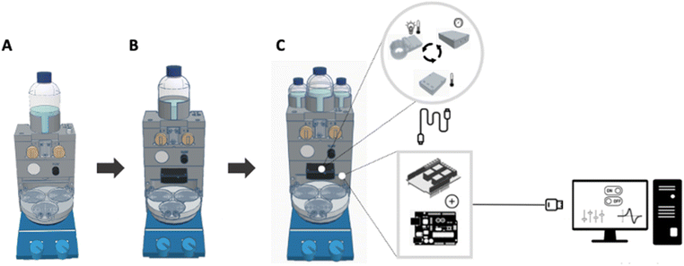 | ||
| Fig. 1 Tinkercad representative design of the proposed modular continuous flow chemistry system. (A) Analog system. (B) Digital system. (C) Scale-up version of the digital system. | ||
The analogue system previously reported by the group was designed to be modular in nature so that it could be easily assembled and dissembled for use with any stirrer hotplate in the laboratory and upgraded by users as desired. Amongst the modules of this system are a solvent block that fits a 500 mL Duran pressure bottle, an injection block containing two 2 mL loop injection valves and a 3D printed mixing chip, which then connects to the 3D printed reactors, a flow unit to regulate the pressure applied, and a base block that provides compressed air to power and run the whole system.21 In order to digitise the flow system and monitor the reaction's temperature, flow rate or other parameter, we envisaged that a range of in-line sensors could be added in as simple plug-in interchangeable modules in the base block. Whilst the sensor data from the module could then be processed by an Arduino microcontroller and displayed in real-time on a display screen, we wanted to develop a simpler to use PC-based interface and as such, decided to incorporate a customized MegunoLink Interface Platform dashboard.25
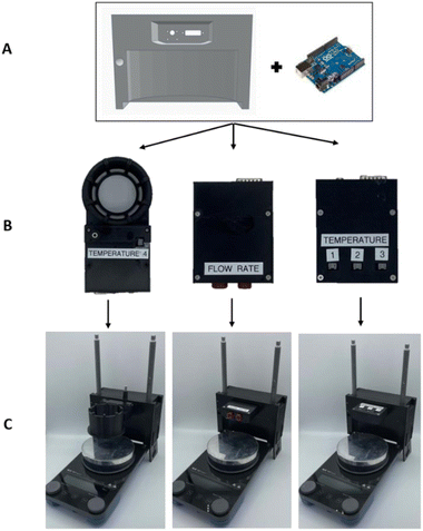
To accomplish this, and develop additional modules, the base block was slightly modified using the free online Tinkercad software tool to firstly accommodate Arduino electronic components in the rear of the base block and secondly, to fit interchangeable sensor modules in the front (Fig. 2). By plugging modules into the front cavity of the base block, it would be possible to connect to the Arduino microcontroller located at the back interior via a DB15 connector. The Arduino code to control the system functionality and the MegunoLink platform was written and uploaded to an Arduino Uno Wi-Fi Rev 2 via the Arduino integrated development environment (IDE).
The sensor modules were designed to fit into the front cavity of the base but were designed to be flexible so that users could easily swop in and out different modules as desired so as to allow temperature, flow rate or other sensors to be incorporated (Fig. 2). Three different modules were designed, each to perform a specific function. The first module, known as the “Temperature Module”, incorporated three waterproof NTC Thermistor Temperature Adapters to simultaneously measure three different temperatures in real-time. The phototemperature module was designed to hold a Kessil lamp to perform photochemical reactions, record temperature measurements, whilst cooling the system with compressed air and the last module was designed to measure the flow rate of the system using an SLF3C-1300F liquid flow sensor.23,24 Conventional liquid sensors such as these are frequently calibrated with water only and as such, the sensor was calibrated with a range of other solvents to accurately monitor their specific flow rate (ESI†). The calibrated solvents were selected based on which ones were most probable to be used in reactions and were compatible with the sensor, including isopropanol (IPA), methanol, ethanol, acetone, and acetonitrile.
As well as incorporating sensors for reaction telemetry, we also wanted to be able to easily scale up the system to enable higher reactant volumes for larger-scale reactions (Fig. 1C). The previous digitized system initially only allowed a maximum of 4 mL of reagent to be manually injected into the flow path due to the use of 2 mL loops (Fig. 3A), and as such, the scaled-up modular version was designed to allow for the automatic injection of up to 200 mL of reactants (Fig. 3B). To achieve this, the injection block was modified to incorporate two solenoid valves at the rear that could be linked to the base block housing the Arduino microprocessor and the solvent block was modified to accommodate three Duran bottles, one 250 mL solvent reservoir bottle, and two 100 mL reactant bottles.
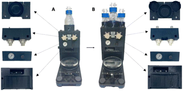 | ||
| Fig. 3 (A) Digitised flow chemistry system on the left, (B) scaled-up version of the continuous flow system on the right. | ||
Each bottle was pressurized with compressed gas (air/nitrogen as desired) and connected to the two solenoid valves. Whilst the initial system for monitoring was able to incorporate a simple Arduino Uno Wifi Rev 2, the Arduino code that controls the scale-up system increased in complexity due to the addition of lines of code to regulate the opening and closing of the valves and as such necessitated the use of an Arduino Mega microprocessor. As the solenoid valves operate at 24 V, a solenoid shield was used to isolate the microprocessor from the current for the valves (ESI†).
Whilst other groups digital approaches have focussed on the use of Python or Arduino screen based interfaces, we wanted to develop a simpler more familiar system for users and so elected to integrate our Arduino code and hardware with the PC interface developed by MegunoLink to allow for facile control of the system and easy visualisation of the reaction telemetry (Fig. 4 and ESI†).25
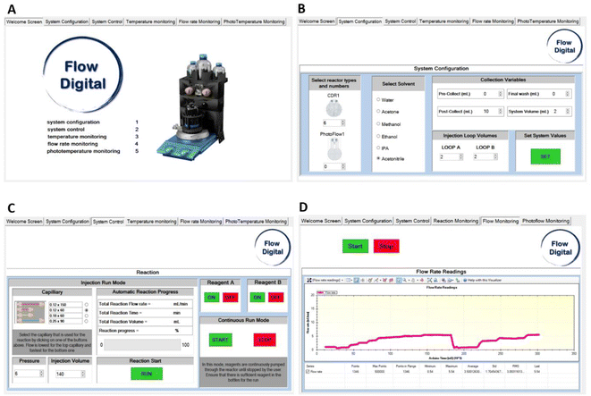 | ||
| Fig. 4 MegunoLink interface of the project. (A) Welcome screen tab. (B) System configuration tab. (C) System control tab. (D) Flow rate monitoring tab. | ||
The PC based interface was designed with multiple tabs to enable the monitoring and automation of the system functionality and sensor values. The configuration tab defines how the flow system is set up (Fig. 4B) allowing users to select the numbers and types of reactors, the solvent used, and the solvent collection variables. The reaction variables are defined under the control tab (Fig. 4C). The factors influencing the reaction outcome are determined by the type of metal capillary used, the pressure applied to the system, and the volume of reactant that will be injected into the flow path. After these variables have been established, the Arduino code calculates how long the valves must be open for, in order for the reactants to flow using eqn (1). The flow rate and pressure correlations were measured for each solvent, resulting in different equations (ESI†). In order to allow for ease of following the reaction progress for users, the Arduino code also updates the reaction output labels within the control tab by displaying a progress bar, the total volume to be collected, and the reaction's overall time and flow rate. While the equation can automate the opening and closing of the valves, the on and off buttons can also be used to manually operate them if any issues arise during a reaction run.
 | (1) |
Equation 1: flow rate and pressure linear equation where a and b are constant numbers.
The final three tabs display the sensor data for each module (Fig. 4D as an example). Each tab contains a start and stop button so that the interface begins processing and displaying sensor data when the user presses the Start button. Therefore, the background noise generated by the sensor is not plotted during non-use, and only data is stored when needed. By leveraging the power and ease of 3D printing techniques and incorporating low-cost electronics, we were able to build the system, totalling less than $2000 per system or less than £1 per reusable flow reactor chip and one that could be easily scaled as per user requirements in a modular fashion.
Results and discussion
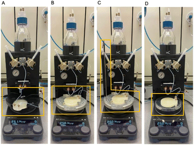
One of the challenges in synthetic chemistry is a lack of reproducibility as a result of the plethora of reaction hardware that is available. Having noticed disparities in the literature from repeating published work in our laboratories, we wanted to design and incorporate flow reactors that would provide reliable telemetry to be able to easily repeat reactions and the designed software was an essential element of that. However, it also necessitated a redesign of the Circular Disk Reactors (CDRs) (Fig. 5A) previously reported by the group that could easily incorporate a temperature sensor in their core to accurately monitor the temperature of the reactor and its flow path.21 The first digital CDR incorporated a temperature cavity within the reactor, allowing a waterproof digital temperature sensor to measure the temperature inside (Fig. 5B). The second reactor was designed to monitor the solvent's actual temperature as the probe would be in direct contact with the reactor's liquid flow path (Fig. 5C) enabling easy comparison of reaction telemetry. The two reactors were designed with Tinkercad and printed with polypropylene on an Ultimaker 3 3D printer using a 0.15 mm profile, 100% infill, printing temperature of 235 °C, and printing speed of 25 mm s−1 (ESI† for further details and G-code modifications).Temperature analyses were carried out between a range of 30 °C to 130 °C, using different equipment covering reactor configurations, flow rates, heat blocks, and reactor designs. The digitized continuous flow system was used together with the temperature sensor module to monitor the temperature and the Flow rate module to control the flow rate of the system.
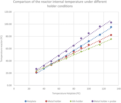
The first reactor set-up was used to evaluate the temperature variations and measurements of one CDR, whether an IKA heat block, a DrySyn heat block, with and without probe and in the absence of a heating block (Fig. 6). The internal temperature of the reactor was measured with the Waterproof Digital Thermal Temperature Sensor connected to the adaptor from the Temperature module. The flow rate module was used to control the flow rate, which was set to 0.2 mL min−1 for all measurements (Chart 1).
The results (Fig. 6), showed that the use of the DrySyn block leads to a higher internal temperature when compared to the set temperature in comparison to the IKA base. From the results it was clear that in all cases, the set temperature was lower than the internal temperature of the flow path, in some cases by as much as 50 °C, starkly illustrating the need for all chemists to accurately record temperatures of any reaction and the associated equipment if they want it to be reproducible by others.
Further temperature analyses were carried out, using two and three CDRs connected in series at different flow rates using the IKA and DrySyn heat blocks. It was found that the heat transfer from the first reactor to the second reactor decreased as the hotplate set temperature rose. As a result, the internal temperature of the second reactor was approximately 5 °C lower than the first one. Moreover, an inverse correlation was observed between the temperature and flow rate; as the flow rate increased, the internal temperature of the reactor decreased. Surprisingly, when a third reactor was connected to the flow system, its internal temperature showed a similar behaviour that of the first reactor which we attributed to pre-heating in the second reactor. Nevertheless, according to prior data and evaluating the temperature fluctuations between the use of different heat blocks, the use of the DrySyn block allowed us to achieve higher internal temperatures, up to 96 °C when compared to the IKA holder, which only reached 89 °C.
Up to this point, the internal temperature of the reactor had been measured but not that of the liquid within the flow channel. Using both types of reactor designs, digital sensor reactor (Fig. 5B) and probe sensor reactor (Fig. 5C), we were able to correlate the temperature variations between the reactor and the flow path (Chart 2). The measurements were performed at different flow rates using the DrySyn block.
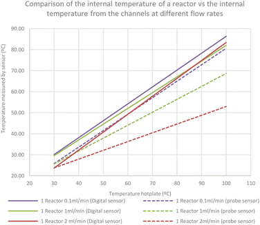 | ||
| Chart 2 Correlation between the internal temperatures of a reactor and the internal temperature from the reactors channel at different flow rates. | ||
An increase of the hotplate set temperature and flow rate led to significant temperature differences as high as 30 °C between the flow path and the reactor. However, when the temperatures of a second reactor connected in series were compared, the differences between the inner cavity and the flow path of the second reactor were not as extensive as in the first case. This result was not surprising as faster flow rates should lead to cooler reactions as the liquid takes time to heat, but this resulting graph starkly illustrates the need to accurately record both the temperature of reactions and their associated flow rates for reproducibility.
Having calibrated the system and gained an understanding of the internal temperature of our CDRs, we elected to optimise a previously reported poor yielding SNAr reaction from the group,21 in a reaction between 2-chloro-5-nitropyridine 1 and 4-nitrophenol 2 where we had previously used a set hotplate temperature of 65 °C, a flow rate of 0.33 mL min−1 with a residence time of 26 minutes (2 CDRs). Following the temperature studies above, the reactions were carried out with the Asynt Drysyn block base with a temperature probe attached.
By monitoring the internal temperature and increasing it to 85 °C, the yield improved from 22% as previously reported to 38% as the internal temperature rose from 55 °C to 85 °C. Addition of a second hotplate, enabled the reaction path to be extended to 6 reactors (Table 1), leading to a yield of 93%. Having optimised the reaction conditions, the reaction was scaled up by loading the two 100 mL Duran bottles with the corresponding reactants. Instead of manually injecting 2 mL of the reactants into each loop, 30 mL of each solution were automatically injected into the flow path from each bottle (Table 1 entry 8). The MegunoLink platform was used not only to monitor the reaction's flow rate and temperature but also to automate the valve opening and closing to allow reagent or solvent to flow through the system. On the configuration tab of the MegunoLink Interface, six CDRs were selected, along with acetonitrile as the solvent. The pressure applied, the capillary used, and the total injection volume were specified in the control tab. Once all the parameters were set, both valves automatically opened to allow the reactant solutions to flow through. The valves closed after 3![[thin space (1/6-em)]](https://www.rsc.org/images/entities/char_2009.gif) :
:![[thin space (1/6-em)]](https://www.rsc.org/images/entities/char_2009.gif) 15 hours as determined by the equation from the Arduino code corresponding to the solvent acetonitrile, an injection volume of 60 mL using a 120 mm × 60 mm RED capillary at a pressure of 6 PSI, obtaining 2.13 g of 5-nitro-2-(4-nitrophenoxy) pyridine 3. From the results obtained (Table 1), it was evident that this system could be used to automate scale-up reactions in an efficient manner. Accordingly, we sought to explore two photochemical reactions in which the phototemperature module and the scale-up system could also be used (Table 2, Scheme 2 and Table 3, Scheme 3).26,27
15 hours as determined by the equation from the Arduino code corresponding to the solvent acetonitrile, an injection volume of 60 mL using a 120 mm × 60 mm RED capillary at a pressure of 6 PSI, obtaining 2.13 g of 5-nitro-2-(4-nitrophenoxy) pyridine 3. From the results obtained (Table 1), it was evident that this system could be used to automate scale-up reactions in an efficient manner. Accordingly, we sought to explore two photochemical reactions in which the phototemperature module and the scale-up system could also be used (Table 2, Scheme 2 and Table 3, Scheme 3).26,27
| Entry | No CDRs (total internal volume) | Injection volume (mL) | Temp. hotplate (°C) | Internal temp. CDR (°C) | Isolated yield (%) |
|---|---|---|---|---|---|
| 1 | 2 (6 mL) | 4 | 65 | 55 | 22 |
| 2 | 2 (6 mL) | 4 | 75 | 65 | 27 |
| 3 | 2 (6 mL) | 4 | 100 | 85 | 38 |
| 4 | 3 (9 mL) | 4 | 100 | 85 | 38 |
| 5 | 4 (12 mL) | 4 | 100 | 85 | 64 |
| 6 | 5 (15 mL) | 4 | 100 | 85 | 69 |
| 7 | 6 (18 mL) | 4 | 100 | 85 | 93 |
| 8 | 6 (18 mL) | 60 | 100 | 85 | 90 |
The scale up synthesis of 1,2-bis(4-methoxyphenyl)-1,2-diphenylethane-1,2-diol (5) (Table 2, Scheme 2)29 and methyl 3-bromo-3-phenylpropanoate (8) (Table 3, Scheme 3)24 were successfully obtained using the phototemperature module. Both reactions were performed with one CDR placed 30 mm below a blue light lamp while being air cooled. Further details of these reactions can be found in the ESI† as well as the 3D printed parts of the system, the Arduino code and MegunoLink interface platform calibrations. In each case, the reaction was also scaled up using the MegunoLink software enabling injection volumes of 25 mL and 40 mL respectively, with comparable yields in each case. For the diol (5) we reduced the flow rate to 0.06 mL min−1 from 0.1 mL min−1 which led to an increased yield of the scaled up reaction.
Conclusions
In summary, three innovative technologies have been combined: continuous flow chemistry, 3D printing, and open-source software to design a low-cost 3D-printed continuous flow chemistry system digitized with Arduino open-source electronics. The MegunoLink PC interface simplified the monitoring and reporting of the sensor data and the control of the system functionality. The extensive tools and services available in the software platform enabled the design of a customized dashboard according to the project's requirements. The development of this system provides a clear understanding of how to accurately monitor system parameters in order to effectively report flow chemical reactions. Furthermore, the affordability of 3D printing technologies and Arduino electronics allows for the standardization of flow chemical synthesis and the expansion of its applications in a low-cost digital platform. Additional low-cost approaches to flow chemistry and the use of Arduino electronics to monitor chemical reactions are currently being investigated and will be reported in due course.Data availability
The design files and source code used in this paper can be found at https://github.com/sthilton/Proteus-Flow-Digital-.Author contributions
Conceptualization, S. H., M. R. P. and M. B. M.; methodology, S. H., and M. B. M.; software, M. B. M. and S. H.; resources: M. B. M. and S. H.; writing – original draft, M. B. M. and S. H.; writing – review & editing, S. H., M. R. P. and M. B. M.Conflicts of interest
M. R. P. and S. T. H. are the inventors of the IKA FLOW, which was developed from their initial design of the continuous flow system previously reported.21,28Acknowledgements
We wish to thank Zurich Insurance for financial support for M. R. P.Notes and references
- (a) M. B. Plutschack, B. Pieber, K. Gilmore and P. H. Seeberger, The Hitchhiker's Guide to Flow Chemistry, Chem. Rev., 2017, 117, 11796–11893 CrossRef CAS PubMed; (b) B. König, P. Kreitmeier, P. Hilgers and T. Wirth, Flow Chemistry in Undergraduate Organic Chemistry Education, J. Chem. Educ., 2013, 90, 934–936 CrossRef; (c) A. Andrea Laybourn, K. Robertson and A. G. Slater, Quid Pro Flow, J. Am. Chem. Soc., 2023, 145, 4355–4365 CrossRef PubMed; (d) M. Seifrid, R. Pollice, A. Aguilar-Granda, Z. M. Chan, K. Hotta, C. T. Ser, J. Vestfrid, T. C. Wu and A. Aspuru-Guzik, Autonomous Chemical Experiments: Challenges and Perspectives on Establishing a Self-Driving Lab, Acc. Chem. Res., 2022, 55, 2454–2466 CrossRef CAS PubMed; (e) S. A. May, Flow Chemistry, Continuous Processing, and Continuous Manufacturing: A Pharmaceutical Perspective, J. Flow Chem., 2017, 7, 137–145 CrossRef CAS; (f) M. Movsisyan, E. I. P. Delbeke, J. K. E. T. Berton, C. Battilocchio, S. V. Ley and C. V. Stevens, Taming hazardous chemistry by continuous flow technology, Chem. Soc. Rev., 2016, 45, 4892–4928 RSC; (g) B. Gutmann, D. Cantillo and C. O. Kappe, Continuous-Flow Technology − A Tool for the Safe Manufacturing of Active Pharmaceutical Ingredients, Angew. Chem., Int. Ed., 2015, 54, 6688–6728 CrossRef CAS PubMed; (h) R. L. Hartman, J. P. McMullen and K. F. Jensen, Deciding Whether To Go with the Flow: Evaluating the Merits of Flow Reactors for Synthesis, Angew. Chem., Int. Ed., 2011, 50, 7502–7519 CrossRef CAS PubMed; (i) L. Capaldo, Z. Wen and T. Noel, A field guide to flow chemistry for synthetic organic chemists, Chem. Sci., 2023, 14, 4230–4247 RSC.
- (a) E. Alvarez, M. Romero-Fernandez, D. Iglesias, R. Martinez-Cuenca, O. Okafor and A. Delorme, et al., Electrochemical Oscillatory Baffled Reactors Fabricated with Additive Manufacturing for Efficient Continuous-Flow Oxidations, ACS Sustain. Chem. Eng., 2022, 10, 2388–2396 CrossRef CAS PubMed; (b) M. Renner and A. Griesbeck, Think and Print: 3D Printing of Chemical Experiments, J. Chem. Educ., 2020, 97, 3683–3689 CrossRef CAS; (c) M. J. Harding, S. Brady, H. O'Connor, R. Lopez-Rodriguez, M. D. Edwards and S. Tracy, et al., 3D printing of PEEK reactors for flow chemistry and continuous chemical processing, React. Chem. Eng., 2020, 5, 728–735 RSC; (d) V. Sans, Emerging trends in flow chemistry enabled by 3D printing: robust reactors, biocatalysis and electrochemistry, Current Opinion in Green and Sustainable Chemistry, Elsevier B.V., 2020, vol. 25 Search PubMed; (e) X. Xu, M. Zhang, P. Jiang, D. Liu, Y. Wang and X. Xu, et al., Direct ink writing of Pd-decorated Al2O3 ceramic based catalytic reduction continuous flow reactor, Ceram. Int., 2022, 48, 10843–10851 CrossRef CAS; (f) A. J. Capel, R. P. Rimington and M. P. Lewis, et al., 3D printing for chemical, pharmaceutical and biological applications, Nat. Rev. Chem, 2018, 2, 422–436 CrossRef.
- (a) H. Gong, A. T. Woolley and G. P. Nordin, High density 3D printed microfluidic valves, pumps, and multiplexers HHS Public Access, Lab Chip, 2016, 16, 2450–2458 RSC; (b) E. G. Gordeev, K. S. Erokhin, A. D. Kobelev, J. Burykina, P. Novikov and V. P. Ananikov, Exploring metallic and plastic 3D printed photochemical reactors for customizing chemical synthesis, Sci. Rep., 2022, 12, 3780 CrossRef CAS PubMed; (c) H. J. Lee, R. C. Roberts, D. J. Im, S. J. Yim, H. Kim and J. T. Kim, et al., Enhanced Controllability of Fries Rearrangements Using High-Resolution 3D-Printed Metal Microreactor with Circular Channel, Small, 2019, 15, 1905005 CrossRef CAS PubMed; (d) E. J. Rastelli, D. Yue, C. Millard and P. Wipf, 3D-printed cartridge system for in-flow photo-oxygenation of 7-aminothienopyridinones, Tetrahedron, 2021, 79, 131875 CrossRef CAS; (e) A. J. Capel, S. Edmondson, S. D. R. Christie, R. D. Goodridge, R. J. Bibb and M. Thurstans, Design and additive manufacture for flow chemistry, Lab Chip, 2013, 13, 4583–4590 RSC; (f) B. Gutmann, M. Köckinger, G. Glotz, T. Ciaglia, E. Slama and M. Zadravec, et al., Design and 3D printing of a stainless steel reactor for continuous difluoromethylations using fluoroform, React. Chem. Eng., 2017, 2, 919–927 RSC; (g) J. M. Neumaier, A. Madani, T. Klein and T. Ziegler, Low-budget 3D-printed equipment for continuous flow reactions, Beilstein J. Org. Chem., 2019, 15, 558–566 CrossRef CAS PubMed; (h) M. C. Maier, A. Valotta, K. Hiebler, S. Soritz, K. Gavric and B. Grabner, et al., 3D Printed Reactors for Synthesis of Active Pharmaceutical Ingredients in Continuous Flow, Org. Process Res. Dev., 2020, 24, 2197–2207 CrossRef CAS.
- Z. X. Rao, B. Patel, A. Monaco, Z. Cao, M. Barniol-Xicota and E. Pichon, et al., 3D-Printed Polypropylene Continuous-Flow Column Reactors: Exploration of Reactor Utility in SNAr Reactions and the Synthesis of Bicyclic and Tetracyclic Heterocycles, Eur. J. Org. Chem., 2017, 44, 499–504 Search PubMed.
- M. C. Maier, R. Lebl, P. Sulzer, J. Lechner, T. Mayr and M. Zadravec, et al., Development of customized 3D printed stainless steel reactors with inline oxygen sensors for aerobic oxidation of Grignard reagents in continuous flow, React. Chem. Eng., 2019, 4, 393–401 RSC.
- (a) J. R. Lake, K. C. Heyde and W. C. Ruder, Low-cost feedback-controlled syringe pressure pumps for microfluidics applications, PLoS One, 2017, 12, 0175089 Search PubMed; (b) F. Menzel, T. Klein, T. Ziegler and J. M. Neumaier, 3D-printed PEEK reactors and development of a complete continuous flow system for chemical synthesis, React. Chem. Eng., 2020, 5, 1300–1310 RSC; (c) S. Baas and V. Saggiomo, Ender3 3D printer kit transformed into open, programmable syringe pump set, HardwareX, 2021, 10, e00219 CrossRef PubMed; (d) M. Iannone, D. Caccavo, A. A. Barba and G. Lamberti, A low-cost push–pull syringe pump for continuous flow applications, HardwareX, 2022, 11, e00295 CrossRef PubMed; (e) R. Rogosic, M. Poloni, R. Marroquin-Garcia, D. Dimech, J. Passariello Jansen, T. J. Cleij, K. Eersels, B. van Grinsven and H. Diliën, Cost-effective, scalable and smartphone-controlled 3D-printed syringe pump - from lab bench to point of care biosensing applications, Phys. Med., 2022, 14, 100051 CrossRef; (f) S. Tsuda, H. Jaffery, D. Doran, M. Hezwani, P. J. Robbins, M. Yoshida and L. Cronin, Customizable 3D Printed ‘Plug and Play’ Millifluidic Devices for Programmable Fluidics, PLoS One, 2015, 10, e0141640 CrossRef PubMed; (g) V. Dragone, V. Sans, M. H. Rosnes, P. J. Kitson and L. Cronin, 3D-printed devices for continuous-flow organic chemistry, Beilstein J. Org. Chem., 2013, 9, 951–859 CrossRef CAS PubMed; (h) F. Menzel, J. Cotton, T. Klein, A. Maurer, T. Ziegler and J. M. Neumaier, FOMSy: 3D-printed flexible open-source microfluidic system and flow synthesis of PET-tracer, J. Flow Chem., 2023, 13, 247–256 CrossRef CAS.
- G. R. D. Prabhu and P. L. Urban, Elevating Chemistry Research with a Modern Electronics Toolkit, Chem. Rev., 2020, 120, 9482–9553 CrossRef CAS PubMed.
- M. S. Magaraci, J. G. Bermudez, D. Yogish, D. H. Pak, V. Mollov and J. Tycko, et al., Toolbox for Exploring Modular Gene Regulation in Synthetic Biology Training, ACS Synth. Biol., 2016, 5, 50 Search PubMed.
- S. Ghosh, K. Aggarwal, V. T. U, T. Nguyen, J. Han and C. H. Ahn, A new microchannel capillary flow assay (MCFA) platform with lyophilized chemiluminescence reagents for a smartphone-based POCT detecting malaria, Microsyst. Nanoeng., 2020, 6, 5 CrossRef CAS PubMed.
- G. di Caprio, C. Stokes, J. M. Higgins, E. Schonbrun and D. A. Weitz, Single-cell measurement of red blood cell oxygen affinity, Proc. Natl. Acad. Sci. USA, 2015, 112, 9984–9989 CrossRef CAS PubMed.
- C. C. Le, M. K. Wismer, Z. C. Shi, R. Zhang, D. Conway and G. Li, et al., A General Small-Scale Reactor to Enable Standardization and Acceleration of Photocatalytic Reactions, ACS Cent. Sci., 2017, 3, 647–653 CrossRef CAS PubMed.
- D. E. Fitzpatrick, M. O'Brien and S. V. Ley, A tutored discourse on microcontrollers, single board computers and their applications to monitor and control chemical reactions, React. Chem. Eng., 2020, 5, 201–220 RSC.
- J. A. White and A. M. Streets, Controller for microfluidic large-scale integration, HardwareX, 2018, 3, 135–145 CrossRef PubMed.
- S. A. Longwell and F. P. M. MicrIO, An open-source autosampler and fraction collector for automated microfluidic input-output, Lab Chip, 2020, 20, 93–106 RSC.
- D. E. Fitzpatrick, T. Maujean, A. C. Evans and S. V. Ley, Across-the-World Automated Optimization and Continuous-Flow Synthesis of Pharmaceutical Agents Operating Through a Cloud-Based Server, Angew. Chem., 2018, 130, 15348–15352 CrossRef.
- D. E. Fitzpatrick, C. Battilocchio and S. V. Ley, A Novel Internet-Based Reaction Monitoring, Control and Autonomous Self-Optimization Platform for Chemical Synthesis, Org. Process Res. Dev., 2016, 20, 386–394 CrossRef CAS.
- R. M. Cardoso, R. O. dos Santos, R. A. A. Munoz, C. D. Garcia and L. Blanes, A multi-pump magnetohydrodynamics lab-on-a-chip device for automated flow control and analyte delivery, Sensors, 2020, 20, 1–9 CrossRef PubMed.
- A. J. Mijalis, D. A. Thomas, M. D. Simon, A. Adamo, R. Beaumont and K. F. Jensen, et al., A fully automated flow-based approach for accelerated peptide synthesis, Nat. Chem. Biol., 2017, 13, 464–466 CrossRef CAS PubMed.
- T. H. Kim, Y. K. Hahn, J. Lee, D. van Noort and M. S. Kim, Solenoid Driven Pressure Valve System: Toward Versatile Fluidic Control in Paper Microfluidics, Anal. Chem., 2018, 90, 2534–2541 CrossRef CAS PubMed.
- R. J. Ingham, C. Battilocchio, J. M. Hawkins and S. V. Ley, Integration of enabling methods for the automated flow preparation of piperazine-2-carboxamide, Beilstein J. Org. Chem., 2014, 12, 641–652 CrossRef PubMed.
- M. R. Penny, Z. X. Rao, B. F. Peniche and S. T. Hilton, Modular 3D Printed Compressed Air Driven Continuous-Flow Systems for Chemical Synthesis, Eur. J. Org. Chem., 2019, 23, 3783–3787 CrossRef.
- (a) M. R. Penny and S. T. Hilton, Design and Development of 3D Printed Catalytically Active Stirrers for Chemical Synthesis, React. Chem. Eng., 2020, 5, 853–858 RSC; (b) M. R. Penny, N. Tsui and S. T. Hilton, Extending practical flow chemistry into the undergraduate curriculum via the use of a portable low-cost 3D printed continuous flow system, J. Flow. Chem., 2021, 11, 19–29 CrossRef CAS; (c) M. R. Penny, Z. X. Rao, R. Thavarajah, A. Ishaq, B. J. Bowles and S. T. Hilton, 3D printed tetrakis(triphenylphosphine)palladium (0) impregnated stirrer devices for Suzuki–Miyaura cross-coupling reactions, React. Chem. Eng., 2023, 8, 752–757 RSC.
- SLF3C-1300F - Next generation in liquid flow sensing up to 40 ml/min and TC feature, available from: https://sensirion.com/products/catalog/SLF3C-1300F/, accessed 10th April 2023 Search PubMed.
- (a) L. Walmsley, S. T. Hilton, E. Sellier, M. Penny and D. Maddox, Control and Monitoring of Temperature in 3D-Printed Circular Disk Reactors for Continuous Flow Photochemistry using Raspberry Pi Based Software, ChemRxiv, preprint, 2021, DOI:10.26434/chemrxiv-2021-cxs25; (b) M. Penny and S. Hilton, 3D Printed Reactors and Kessil Lamp Holders for Flow Photochemistry: Design and System Standardization, ChemRxiv, preprint, 2021, DOI:10.26434/chemrxiv-2021-kmxgd; (c) M. R. Penny and S. Hilton, 3D Printed Reactors and Kessil Lamp Holders for Flow Photochemistry: Design and System Standardization, J. Flow. Chem., 2023 DOI:10.1007/s41981-023-00278-w.
- https://www.megunolink.com/, accessed 8th April 2023.
- K. Kate Volpe and E. E. Podlesny, J. Chem. Educ., 2020, 97, 586–591 CrossRef.
- D. Cantillo, O. de Frutos, J. A. Rincon, C. Mateos and C. O. Kappe, A Scalable Procedure for Light-Induced Benzylic Brominations in Continuous Flow, J. Org. Chem., 2014, 79, 223–229 CrossRef CAS PubMed.
- https://www.ika.com/en/Products-LabEq/FLOW-System-pg919/, accessed 12-07-2023.
- K. Kate Volpe and E. E. Podlesny, Modernization of a Photochemical Reaction for the Undergraduate Laboratory: Continuous Flow Photopinacol Coupling, J. Chem. Educ., 2020, 97(2), 586–591 CrossRef.
Footnote |
| † Electronic supplementary information (ESI) available. See DOI: https://doi.org/10.1039/d3dd00128h |
| This journal is © The Royal Society of Chemistry 2023 |

