 Open Access Article
Experimental determination of tantalum L-shell fluorescence yields and Coster–Kronig transition probabilities
Nils
Wauschkuhn
 *,
Katja
Frenzel
 ,
Burkhard
Beckhoff
and
Philipp
Hönicke

Physikalisch-Technische Bundesanstalt, Abbestr. 2-12, 10587 Berlin, Germany. E-mail: nils.wauschkuhn@ptb.de
First published on 9th December 2022
Abstract
Using radiometrically calibrated instrumentation of the Physikalisch-Technische Bundesanstalt, the L-shell fluorescence yields and Coster–Kronig factors of tantalum (including the uncertainty budget) were experimentally determined based on transmission and X-ray fluorescence experiments. The determined fluorescence yields (ωL3 = 0.247(12), ωL2 = 0.278(15), ωL1 = 0.157(12)) were independently validated through XRR-GIXRF experiments. Both the Coster–Kronig factors (f23 = 0.123(84), f13 = 0.328(152), f12 = 0.14(11)) as well as the fluorescence yields are in good agreement with the most established databases in the field of X-ray fluorescence.
1 Introduction
Knowledge about atomic fundamental parameters (FPs), such as the fluorescence yield, the photoionization cross section and the Coster–Kronig transition probabilities, is of great importance for any quantitative analysis involving X-ray fluorescence (XRF). Most of the available experimental and theoretical FP values for different elements were obtained more than forty years ago. For some chemical elements and some FPs, the tabulated data is based solely on interpolations as no experimental or theoretical data exists. Unfortunately, the uncertainties of most tabulated FP data are often not available or only estimated. As this is certainly an improvable situation, the International initiative on X-ray fundamental parameters1 and others are working on revisiting and updating FP databases with new experiments and calculations employing state-of-the-art techniques.In this work, the tantalum L-shell FPs, namely the fluorescence yields and the Coster–Kronig factors, are being experimentally redetermined. Tantalum is a key element in microelectronics,2,3 the solar industry,4 medicine and other fields. However, the availability of experimentally determined Ta-L-shell FPs is rather scarce. Much of the available experimental data is older than 30 years, and the uncertainties for the most common tabulations5,6 are only estimated. In this work, we apply the reference-free XRF equipment of Physikalisch-Technische Bundesanstalt (PTB)7 and dedicated transmission and fluorescence measurements8 to revisit these parameters for tantalum.
2 Experimental procedure
2.1 Photon-in/photon-out experiment
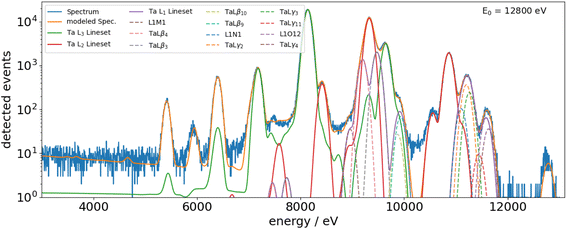
The experiments were performed at the BAMline, the wavelength-shifter beamline,9 at the BESSY II electron storage ring. This beamline provides hard monochromatic X-ray synchrotron radiation in the photon energy range from 5 keV up to 60 keV. Usually, the double crystal monochromator (DCM, with Si(111) crystals, dE/E = 0.2% between 8 and 50 keV) is used for applications comparable to the one in this study. The experiments were carried out using a vacuum chamber that was developed in-house10 and was equipped with calibrated photodiodes and an energy-dispersive silicon drift detector with experimentally determined response functions and radiometrically calibrated detection efficiency.11 The sample was placed into the center of the chamber by means of an x–y scanning stage, and the incident angle θin between the surface of the sample and the incoming beam was set to 45°. As a sample, we obtained a nominally 250 nm thick Ta deposition on a Si3N4 membrane. The membrane has a thickness of nominally 1000 nm. Furthermore, a blank Si3N4 membrane deposition was used to subtract the membrane contribution.For both samples, transmission experiments were performed in the vicinity of the Ta-L absorption edges between 7 keV and 13 keV. In addition, the X-ray fluorescence emission from the coated sample was measured for photon energies ranging from about 10 keV to 13 keV. From these experiments, the Ta-L-shell fluorescence yields and the Coster–Kronig factors can be determined as described below.
The procedure for determining L-shell fluorescence yields as well as Coster–Kronig factors using physically calibrated instrumentation for the reference-free X-ray spectrometry (XRS) of PTB is already quite well established.8,12–14 Here, Sherman's equation15 provides the basis for the calculation of fluorescence intensities of thin foils. It is a product of the incident monochromatic photon flux, a fluorescence production factor for a given shell σS, an instrumentation factor containing the solid angle of detection and the detection efficiency and the self-attenuation correction factor. This factor considers the attenuation of the photons on their way through the sample. For the incoming photons Φ0(E0), the attenuation on their way to the point of interaction is considered; for the fluorescence photons Φid(E0), the attenuation on their way from the point of interaction to the detector is considered. Through employing tunable photon sources or, as recently shown, also through employing energy dispersive detectors,16 this factor can be easily determined by transmission measurements for the relevant photon energies.
The fluorescence production factor σLi is defined as follows:
| σL3(E0) = ωL3(τL3(E0) + f23τL2(E0) + [f13 + f12f23]τL1(E0)) | (1) |
| σL2(E0) = ωL2(τL2(E0) + f12τL1(E0)) | (2) |
| σL1(E0) = ωL1τL1(E0) | (3) |
It is dependent on the photon energy E0 and is calculated employing the respective subshell fluorescence yield ωLi, the subshell photoionization cross sections τLi(E0) as well as the Coster–Kronig factors fji. The latter are irrelevant for photon energies below the edge energy of the respective subshell as the photoelectric cross section is zero for energies below the corresponding subshell threshold energy. Thus, for photon energies between EL3 and EL2, σL3(E0) is simply the product of the fluorescence yield and the photoionization cross section so that the fluorescence yield ωL3 can be derived. By further employing this selective excitation to the other edges, also the L2- and L1-subshell fluorescence yields as well as the Coster–Kronig factors can be determined.
In other words, if EL3 ≤ E0 ≤ EL2, the fluorescence production factor for L3 is reduced to
 | (4) |
 | (5) |
 are known due to the use of calibrated instrumentation.7 The sample-specific attenuation correction factor Mi,E0 for the incident (E0) – as well as the fluorescence radiation (Ei) – is calculated according to eqn (5) using the experimentally determined sample-specific attenuation coefficients μS(E0)ρd and μS(Ei)ρd.
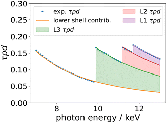
Employing the experimental μS(E0)ρd and μS(Ei)ρd values, one can calculate the total sample-specific photoionization cross sections τS(E0)ρd and μS(Ei)ρd by removing the scattering contributions. For this purpose, we derive the relative scattering contribution at each photon energy from a database (e.g. X-raylib) and use this data to determine τS(E0)ρd. The thereby obtained photoionization cross sections are shown in Fig. 2 as blue dots. For the determination of the subshell fluorescence yields as well as the Coster–Kronig factors, one needs to isolate the subshell photoionization cross sections τLi(E0)ρd. This is performed by scaling the Ebel polynomials17 for the lower bound shells as well as the three L-subshells to the τS(E0)ρd as shown in the figure. To minimize the effect of the fine structure on this scaling process, only points far away from the edges, where the fine structure is negligible, were chosen for the scaling of the Ebel polynomials.
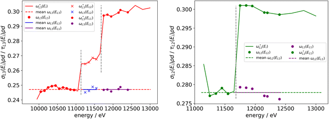
With the τLi(E0)ρd, all relevant parts of eqn (4) are known, and it can be solved for the fluorescence yield. The same procedure is applied for the L2- and L1-shells. By applying the same procedure for incident energies above the subsequent absorption edges, the Coster–Kronig factors can be derived. In Fig. 3, this is shown for the case of ωL3 and ωL2. Here, the derived fluorescence yield values marked with a star, for example  , are being calculated by only taking into account the normalized fluorescence intensity of the L3-shell as well as the derived τL3(Ei)ρd (red line in Fig. 3). If the incident photon energy is above the subsequent absorption edge (marked as gray dashed vertical lines), the
  jumps due to the additional Coster–Kronig-related contributions to the total effective photoionization cross section. This cross section is namely the term f23τL2(E0) in the case shown in Fig. 3 as red crosses. As the fluorescence yield value must be constant and not dependent on the incident photon energy, the Coster–Kronig factor can be determined so that the Coster–Kronig corrected ωL3(EL2) matches the one determined for an excitation below the L2 absorption edge.
2.2 Validation measurement with combined XRR and GIXRF
As an independent validation of the experimentally determined L3 fluorescence yield, a combined reference-free grazing incidence X-ray fluorescence and X-ray reflectometry (GIXRF-XRR) measurement18 was carried out on two different tantalum layer samples. These experiments were carried out employing an ultrahigh vacuum chamber that was built in-house and is dedicated to reference-free XRS19 at PTB's four-crystal-monochromator beamline.20 The two layer samples employed consist of pure Ta layers on silicon wafers with nominal thicknesses of 30 nm and 50 nm. The energy of the incident beam was set to 10 keV to only excite the L3 shell of tantalum. For both samples, the incident-angle-dependent Ta-L3 fluorescence emission as well as the reflected incident radiation have been recorded. The experimental data including a basic evaluation (spectra deconvolution, normalization to incident photon flux and solid angle of detection) are shown in Fig. 4.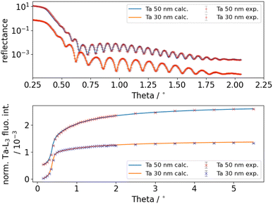 | ||
| Fig. 4 Comparison of measured and calculated data: reflectance (top) and the normalized fluorescence intensity (bottom). | ||
To determine the fluorescence production cross section (FPCS) from the experimental data, a quantitative combined modeling of the GIXRF-XRR data was performed as shown in ref. 21. For this purpose, the sample was modeled by the following layer stack: A thin carbonaceous contamination covering tantalum oxide which is on tantalum on native oxide which covers the silicon wafer. For each layer, with the exception of the substrate, the thickness and relative density were used as model parameters. In addition, the top surface roughness as well as the tantalum layer roughness were modeled. The roughness of the tantalum oxide layer was set to be the same as the previous one. Experimental parameters such as the beam divergence or the photodiode's dark current were modeled as well. The modeling process is realized using the Sherman equation,15 which is shown below, for the GIXRF measurement and using the matrix method22 for the XRR measurement.
 | (6) |
Here, the experimentally derived fluorescence count rate F(θi, Ei) of the line set related to the Ta-L3-edge, excited using photons of energy Ei at an incident angle θi, is the essential measurand. A normalization to the effective solid angle of detection  , the incident photon flux Φ0, and the detection efficiency of the used fluorescence detector εEf is also required. The experimental data can be reproduced by calculating the X-ray standing wave field intensity distribution IXSW(θi, Ei, z), a numerical integration in conjunction with the depth distribution P(z) of the tantalum distribution and an attenuation correction factor. For quantitative modeling, the atomic FPs, namely the L3-subshell photoionization cross section τ(Ei) and the fluorescence yield ωL3, and material-dependent parameters, such as the weight fraction Wi of element i within the matrix as well as the density ρ of the matrix, must also be considered. For the latter, we have adopted the density of the 50 nm Ta layer (14.2 g cm−3) from a previous study of the same sample23 in order to reduce the degrees of freedom. The ratio of this density with respect to the Ta bulk density was applied to both the Ta2O5 and the Ta layers of both samples.
The relevant optical constants were taken from X-raylib6 using the respective ρbulk and are also scaled using each material's relative density. The FPCS for the Ta-L3-shell was also taken from X-raylib and is scaled employing a factor during the modeling. The optimization was performed using a Markov chain Monte Carlo (MCMC) algorithm.24
The final model calculations are also shown in Fig. 4 and agree very well with the experimental data. The determined layer thickness of the Ta layers is about 28.9 nm or 46.9 nm and thus reasonably in line with the nominal values.
3 Results
The results derived for the Ta-L-subshell fluorescence yields are shown in Fig. 5 as well as in Table 1 in comparison to selected data from the literature. They were averaged from the values derived at the different excitation photon energies below the subsequent absorption edge as indicated in Fig. 3. The uncertainty budget of the determined fluorescence yields is calculated using the relative uncertainty contributions of the involved parameters. The main contributors to the total uncertainty budget are the determined subshell photoionization cross sections (∼2.5% for L3, ∼6% for L1) and the uncertainty contribution of the spectral deconvolution (∼2%). The uncertainty budget one can achieve by employing PTB's reference-free XRF approach for the determination of atomic FPs is discussed in more detail in ref. 25.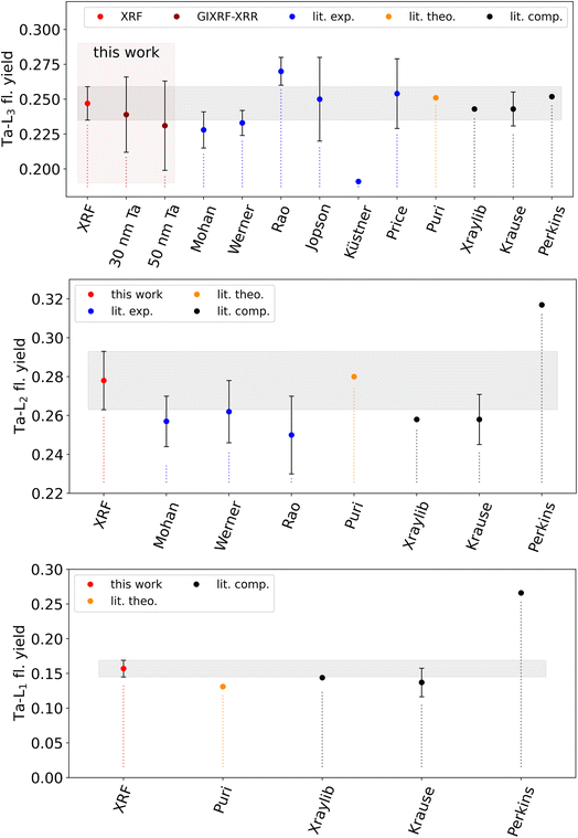 | ||
| Fig. 5 Experimentally determined Ta-L fluorescence yields in comparison to selected literature data from other experimental works of Mohan,28 Werner,29 Rao,30 Jopson,31 Küstner32 and Price33 (blue), theoretical calculations by Puri26 (orange) or commonly used compilations5,6,34 (black). The experimental uncertainties of our values are plotted as gray boxes for easier comparison. For the Ta-L3 fl. yield, both the XRF result and the GIXRF-XRR values are shown. | ||
In general, our experimental values agree reasonably well with commonly used X-raylib6 data and the theoretical predictions of Puri et al.26 Significant deviations larger than the uncertainty are observed for the L2-shell yield with respect to X-raylib and the L1-shell yield with respect to Puri. The agreement with the older experimental data shown is good considering the stated respective uncertainties. It should be noted that there are more published values for the L-subshell fluorescence yields of Ta with different origins (experimental or interpolated). They are well summarized in a recent work by Sahnoune et al.27
From the GIXRF-XRR modeling, Ta-L3 fluorescence yield values of 0.239(27) (sample A, 30 nm Ta) and 0.231(32) (sample B, 50 nm Ta) were received, assuming that the L3-subshell photoionization cross section for Ta from X-raylib at the employed excitation photon energy of 10 keV is correct. These results are also shown in Table 1 and Fig. 5 in combination with the other data. The uncertainty of the GIXRF determined value is estimated based on the confidence interval of the modeling and an estimated uncertainty of the tabulated L3-subshell photoionization cross section. Unfortunately, the uncertainties are too large to reliably judge which fluorescence yield is more accurate. For such small deviations between the determined experimental value and the tabulated value, the sensitivity of the GIXRF-XRR approach is not sufficient. This is mainly due to the strong parameter correlation with the layer densities. If the densities could be determined independently, and thus kept fixed for the modeling, it would significantly improve the sensitivity for the fluorescence production cross section.
The experimentally determined Coster–Kronig factors are also shown in Table 1 in comparison to selected data from the literature. A graphical comparison is also shown in Fig. 6 for f23. The derived value for f23 is in good agreement with the data from the literature, even when considering a much lower uncertainty budget. Similar behavior can be found for f13, where the observed differences are much lower than our stated uncertainty. Only for f12, are the deviations with respect to the commonly used database values somewhat large but still within our stated uncertainty.
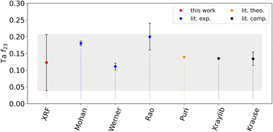 | ||
| Fig. 6 Experimentally determined Coster–Kronig factor f23 for Ta-L fluorescence in comparison to selected literature data from other experimental works of Mohan,28 Werner29 and Rao30 (blue), theoretical calculations by Puri26 (orange) or commonly used compilations5,6 (black). The experimental uncertainty of our value is plotted as a gray box for easier comparison. | ||
The determined relative uncertainties of the Coster–Kronig factors are higher than those of the fluorescence yields because of the required error propagation. For the Coster–Kronig factors, the relation between the different subshell photoionization cross sections increases the total relative uncertainty. Hence, a reliable uncertainty budget for the determined Coster–Kronig factors leads to large uncertainties in the order of the values themselves.8 But as can be seen by the non-agreeing values by Mohan and Werner, our uncertainty seems more reasonable and is more reliable.
4 Conclusion
The tantalum L-shell fluorescence yields and Coster–Kronig factors have been experimentally determined employing the radiometrically calibrated instrumentation of PTB using Ta-coated Si3N4 membranes. The determined fluorescence yields agree well with the commonly used X-raylib tables except for the L2-shell. Here, our value is slightly larger than the tabulated value. The achieved experimental uncertainties for the three fluorescence yields are in the same order as the Krause estimates.5 This not only puts the estimated uncertainties on more solid ground, it also allows us to conclude with reasonable reliability that the estimated uncertainties for the L-shell yields of neighboring elements are in the right order of magnitude as well. Considering both the determined fluorescence yields and the Coster–Kronig factors, we can conclude that the X-raylib table has a relatively good collection of the relevant Ta FPs. This is also in line with observations from earlier FP determinations from our group.21,25,35 Thus, the X-raylib tables are a very good starting point if a consistent database is needed.Conflicts of interest
There are no conflicts to declare.Acknowledgements
This project has received funding from the ECSEL Joint Undertaking (JU) IT2 under grant agreement No. 875999. The JU receives support from the European Union's Horizon 2020 research and innovation programme and the Netherlands, Belgium, Germany, France, Austria, Hungary, the United Kingdom, Romania and Israel.References
- International initiative on x-ray fundamental parameters, 2021, Accessed: 2022-06-03. https://www.exsa.hu/?inh=635 Search PubMed.
- T. Shoki, T. Kinoshita, N. Sakaya, M. Hosoya, R. Ohkubo and Y. Usui, et al., Damage-free extreme ultraviolet mask with TaBN absorber, J. Vac. Sci. Technol., B: Microelectron. Nanometer Struct.–Process., Meas., Phenom., 2003, 21(6), 3021–3026 CrossRef CAS , https://avs.scitation.org/doi/abs/10.1116/1.1610004.
- K. Choi and S. Yoon, Characteristics of Pt and TaN Metal Gate Electrode for High-κ Hafnium Oxide Gate Dielectrics, Electrochem. Solid-State Lett., 2004, 7(3), G47, DOI:10.1149/1.1645754.
- X. Yang, E. Aydin, H. Xu, J. Kang, M. Hedhili and W. Liu, et al., Tantalum Nitride Electron-Selective Contact for Crystalline Silicon Solar Cells, Adv. Energy Mater., 2018, 8(20), 1800608 CrossRef , https://onlinelibrary.wiley.com/doi/abs/10.1002/aenm.201800608.
- M. O. Krause, Atomic Radiative and Radiationless Yields for K and L shells, J. Phys. Chem. Ref. Data, 1979, 8(2), 307–327 CrossRef CAS.
- T. Schoonjans, A. Brunetti, B. Golosio, M. S. del Rio, V. A. Solé and C. Ferrero, et al., The xraylib library for X-ray–matter interactions. Recent developments, Spectrochim. Acta, Part B, 2011, 66, 776–784 CrossRef CAS.
- B. Beckhoff, Reference-free X-ray spectrometry based on metrology using synchrotron radiation, J. Anal. At. Spectrom., 2008, 23, 845–853 RSC.
- M. Kolbe, P. Hönicke, M. Müller and B. Beckhoff, L-subshell fluorescence yields and Coster-Kronig transition probabilities with a reliable uncertainty budget for selected high- and medium-Z elements, Phys. Rev. A: At., Mol., Opt. Phys., 2012, 86, 042512 CrossRef.
- W. Görner, M. P. Hentschel, B. R. Müller, H. Riesemeier, M. Krumrey and G. Ulm, et al., BAMline: the first hard X-ray beamline at BESSY II, Nucl. Instrum. Methods Phys. Res., Sect. A, 2001, 467–468(1), 703–706 CrossRef.
- M. Kolbe, B. Beckhoff, M. Krumrey and G. Ulm, Thickness determination for Cu and Ni nanolayers: Comparison of reference-free fundamental-parameter based X-ray fluorescence analysis and X-ray reflectometry, Spectrochim. Acta, Part B, 2005, 60, 505–510 CrossRef.
- F. Scholze and M. Procop, Modelling the response function of energy dispersive X-ray spectrometers with silicon detectors, X-Ray Spectrom., 2009, 38(4), 312–321 CrossRef CAS.
- P. Hönicke, M. Kolbe, M. Müller, M. Mantler, M. Krämer and B. Beckhoff, Experimental verification of the individual energy dependencies of the partial L-shell photoionization cross sections of Pd and Mo, Phys. Rev. Lett., 2014, 113(16), 163001 CrossRef PubMed.
- M. Kolbe and P. Hönicke, Fundamental parameters of Zr and Ti for a reliable quantitative X-ray fluorescence analysis, X-Ray Spectrom., 2015, 44(4), 217–220 CrossRef CAS.
- Y. Ménesguen, M. C. Lépy, J. M. Sampaio, J. P. Marques, F. Parente and M. Guerra, et al., A combined experimental and theoretical approach to determine X-ray atomic fundamental quantities of Tin, X-Ray Spectrom., 2018, 47(5), 341–351 CrossRef.
- J. Sherman, The theoretical derivation of fluorescent X-ray intensities from mixtures, Spectrochim. Acta, 1955, 7, 283–306 CrossRef CAS.
- H. Huang, K. Sequoia, M. Yamaguchi, K. J. Boehm, K. Engelhorn and J. Walker, et al., Improved x-ray mass attenuation coefficient (opacity) measurements for Fe, Ni and Au, J. Phys. B: At., Mol. Opt. Phys., 2021, 54(11), 115003 CrossRef CAS.
- H. Ebel, R. Svagera, M. F. Ebel, A. Shaltout and J. H. Hubbell, Numerical description of photoelectric absorption coefficients for fundamental parameter programs, X-Ray Spectrom., 2003, 32, 442–451 CrossRef CAS.
- P. Hönicke, B. Detlefs, E. Nolot, Y. Kayser, U. Mühle and B. Pollakowski, et al., Reference-free grazing incidence X-ray fluorescence and reflectometry as a methodology for independent validation of X-ray reflectometry on ultrathin layer stacks and a depth-dependent characterization, J. Vac. Sci. Technol., A, 2019, 37(4), 041502 CrossRef.
- J. Lubeck, B. Beckhoff, R. Fliegauf, I. Holfelder, P. Hönicke and M. Müller, et al., A novel instrument for quantitative nanoanalytics involving complementary X-ray methodologies, Rev. Sci. Instrum., 2013, 84, 045106 CrossRef CAS PubMed.
- M. Krumrey, Design of a Four-Crystal Monochromator Beamline for Radiometry at BESSY II, J. Synchrotron Radiat., 1998, 5(1), 6–9 CrossRef CAS PubMed.
- P. Hönicke, R. Unterumsberger, N. Wauschkuhn, M. Krämer, B. Beckhoff and P. Indelicato, et al., Experimental and theoretical approaches for determining the K-shell fluorescence yield of carbon, Radiat. Phys. Chem., 2022, 110501 Search PubMed.
- F. Abelès, Recherches sur la propagation des ondes électromagnétiques sinusoïdales dans les milieux stratifiés, Ann. Phys., 1950, 12(5), 596–640 Search PubMed , https://doi.org/10.1051%2Fanphys%2F195012050596.
- R. Ciesielski, Q. Saadeh, V. Philipsen, K. Opsomer, J. P. Soulié and M. Wu, et al., Determination of optical constants of thin films in the EUV, Appl. Opt., 2022, 61(8), 2060 CrossRef CAS PubMed.
- D. Foreman-Mackey, D. W. Hogg, D. Lang and J. Goodman, emcee: The MCMC Hammer, Publ. Astron. Soc. Pac., 2013, 125(925), 306–312 CrossRef.
- R. Unterumsberger, P. Hönicke, J. Colaux, C. Jeynes, M. Wansleben and M. Müller, et al., Accurate experimental determination of Gallium K- and L3-shell XRF fundamental parameters, J. Anal. At. Spectrom., 2018, 33(6), 1003–1013 RSC.
- S. Puri, D. Mehta, B. Chand, N. Singh and P. N. Trehan, L shell fluorescence yields and Coster-Kronig transition probabilities for the elements with 25 < Z < 96, X-Ray Spectrom., 1993, 22(5), 358–361 CrossRef CAS.
- Y. Sahnoune, A. Kahoul, Y. Kasri, B. Deghfel, D. E. Medjadi and F. Khalfallah, et al., L1, L2, and L3 subshell fluorescence yields: Updated database and new empirical values, Radiat. Phys. Chem., 2016, 125, 227–251 CrossRef CAS.
- S. Mohan, R. W. Fink, R. E. Wood, J. M. Palms and P. V. Rao, Electron capture decay of 181W: L subshell fluorescence and Coster-Kronig yields in Ta, Z. Phys., 1970, 239(5), 423–428 CrossRef CAS.
- U. Werner and W. Jitschin, L-vacancy decay in heavy elements (72 ≤ Z ≤ 82) by the synchrotron photoionization method, Phys. Rev. A: At., Mol., Opt. Phys., 1988, 38(8), 4009–4018 CrossRef CAS PubMed.
- P. V. Rao and B. Crasemann, L2-L3N Coster-Kronig Transition Probabilities and L-Subshell Fluorescence Yields of Hg and Ta, Phys. Rev., 1965, 139(6A), A1926–A1929 CrossRef.
- R. C. Jopson, J. M. Khan, H. Mark, C. D. Swift and M. A. Williamson, Fluorescence Yields of the LII and LIII Shells in Heavy Elements, Phys. Rev., 1964, 133(2A), A381–A384 CrossRef.
- H. Küstner and E. Arends, Ausbeutekoeffizienten, Intensitätsverhältnisse und Absorptionswahrscheinlichkeiten in der L-Serie der Schwerelemente, Ann. Phys., 1935, 414(5), 443–472 CrossRef.
- R. E. Price, H. Mark and C. D. Swift, Measurements of L2- and L3-Subshell Fluorescence Yields in Heavy Elements, Phys. Rev., 1968, 176(1), 3–10 CrossRef CAS.
- S. T. Perkins, D. E. Cullen, M. H. Chen, J. Rathkopf, J. Scofield and J. H. Hubbell. Tables and graphs of atomic subshell and relaxation data derived from the LLNL Evaluated Atomic Data Library (EADL), Z = 1-100, UCRL 50400, vol. 30, 1991 Search PubMed.
- P. Hönicke, M. Kolbe, M. Krumrey, R. Unterumsberger and B. Beckhoff, Experimental determination of the oxygen K-shell fluorescence yield using thin SiO2 and Al2O3 foils, Spectrochim. Acta, Part B, 2016, 124, 94–98 CrossRef.
| This journal is © The Royal Society of Chemistry 2023 |

