DOI:
10.1039/D2MA01029A
(Paper)
Mater. Adv., 2023,
4, 1171-1187
Renewable micro hydroxyapatite (mHA) extracted from animal bones, and fabricated mHA-Jute-vinyl ester bio-composite as an intumescent green flame retardant material
Received
11th November 2022
, Accepted 17th January 2023
First published on 20th January 2023
Abstract
In this paper, we synthesized highly functionalized micro hydroxy apatite (mHA) from animal bones by a decomposition method using extended base treatment, and applied it as a flame-retardant material (FRM) through a dip-coating method as a heat-shielding layer on pure jute (PJ). Wet depositions of charged anionic and cationic polyelectrolytes create a few to several coating layers by the L-B-L method on the surface of PJ through strong electrostatic interactions, generating mHA-Jute. In addition, a strong cementing action materializes through inter-ionic interactions between the PJ surface and mHA, and is compared in flame-retardancy tests through cone calorimetry analysis. The heat release rates (HRRs) of PJ and mHA-Jutes (0.5 wt%, 1.0 wt%, 2.0 wt%, and 3.0 wt%) are displayed in the primary and secondary stages. The HRRs gradually decreased from PJ (177) to 3.0 wt% mHA-Jute 36 (388%), owing to the strong thermal shielding effect of the mHA deposited on the PJ core due to lignocellulose fiber linked with mHA. Next, we fabricated mHA-Jute with vinyl ester resin (VER) bio-composites and calculated the HRRs. The HRRs of mHA-Jute-VER bio-composites showed superior thermal shielding action over the blank PJ-VER bio-composite and superior HRRs of 291 s, 131 s, and 41 s were observed from PJ-VER to 1.0 wt%, 2.0 wt%, and 3.0 wt% mHA-Jute-VERs, respectively, due to the formation of thermal shielding layers. Higher burning times and burning rates were reported for mHA-Jute-VERs compared to PJ-VER bio-composites. The impact energies of mHA-Jute-VER increased up to 47% from 0.5 wt% to 3.0 wt% mHA deposition. In addition, the limiting oxygen index (LOI) of 3.0 wt% mHA-Jute-VER showed a superior value (27%) compared to the PJ-VER bio-composite. Moreover, ignition resistance and self-extinguishing competencies were observed on coated fabrics with 3.0 wt% mHA-Jute-VER, which could be a great advantage for indoor fire-quenching applications. We have also explained the FR mechanism of the proposed mHA-Jute-VER bio-composite by comparing the elimination of various combusted gases of CO2, CO, CH4, and O2.
1. Introduction
Smart and ideal fire-retardant materials (FRM) are greatly required to prevent fire from spreading in fatal fire tragedies. A perfect FRM can sustain its structural integrity and thermal compatibility in a flame as a thermos-sensitive fire material that can quickly extinguish the fire.1–3 The interior decorations in multi-story high-rise apartments often catch fire due to electric short circuits, natural disasters, and man-made mistakes. Jute fiber mats are potential natural fibers for designing various interior decorations, such as domestic furniture covers, wall paints, interior carpets and curtains, and covers for multi-purpose gadgets, including toys. These jute fiber mats will catch fire due to low thermal stability. To overcome the low thermal stability, FRM is an alternative option to prevent it catching fire. Micro-scale-level depositions of FRM on jute/cotton fiber mats can greatly control the burning rate and save lives and assets.4,5
Lignocellulosic fibers, like jute, cotton, ramie, coir, flax, hemp, and sisal bamboo, have been explored as reinforcements in bio-composites.6–8 These bio-composites were reported to exhibit the potential to replace conventional polymers and polymer composites and polymer matrix composites incorporating synthetic fibers in non-structural and semi-structural applications like furniture, the interiors of automobiles and airplanes, electrical fittings, and cutlery.9,10 However, for commercial applications like furniture and the interiors of automobiles and airplanes, the use of materials with acceptable strength and high fire resistance is desirable. Presently, halogen-based flame retardants are employed in the majority of commercial applications. Although these flame retardants show effective flame retardancy, they are hazardous to the environment as they produce harmful smoke and toxic gases during burning. Hence, due to the drawbacks of halogen-based flame retardants, interest in the use of halogen-free flame retardants has increased.11,12
Animal bones compose of hydroxy apatite (HA) with a chemical formula of (Ca10(OH)2(PO4)6) and type I collagen fibrils. Bones consist of 70% HA, 20% collagen, and 10% water.13,14 In mammals, the main mineral form is called biological apatite, which is a hydroxyl-deficient and carbonate-rich apatite with a Ca/P ratio less than 1.67. HA shows extraordinary biocompatibility for applications in biomedical fields.15,16 Nevertheless, HA generally displays high fragility, and poor flexibility because HA commonly forms particles, short rods, or needles. Recently, we have found that ultra-long micro-sized HA shows high flexibility and can solve the problem of the high brittleness and poor flexibility of HA materials.17 Micro hydroxy apatite (mHA) is a promising kind of biomaterial with many advantages, such as high biocompatibility, high flexibility, good mechanical properties, high thermal stability, and fire resistance. Subsequently, mHA is also an excellent building material for the construction of flexible fire-resistant materials, and we extracted mHA from animal bones after cleaning off the muscles attached to the bone structure. Considering the above-mentioned advantages, we determined that flexible fire-resistant mHA deposition is suitable for the application of fire-retardant material by deposition on jute fiber mats.18
In current scientific scenarios, the dip-coating method is a highly popular method to establish micro-coatings on lignocellulosic natural fibers. The manufacture of bulk industrial appliances such as coated fabrics is mainly used for biomedical, mechanical, and other engineering applications.19 In addition, other uses include the preparation of multilayered sensory coatings, implanted functional materials, sol–gel nanoparticle coatings, self-assembled monolayers (SAMs), and layer-by-layer (L-B-L) micro-assemblies. The dip-coating method is dependent on the nature of the polyelectrolyte, temperature, and pH. Recently, several groups have studied the dip-coating method to modify the surface texture and properties of lignocellulosic fabrics, including mechanical strength and flame retardancy.20 Li and co-workers reported an intumescent all-polymer multilayer nano-coating capable of extinguishing flames on fabrics and the flame-retardant behavior of polyelectrolyte clay thin film assemblies on cotton fabrics.21,22 Attia N. F. et al. reported on graphene sheets as a new generation of flame-retardant materials due to formation of protective char layers on the host polymeric materials.23–30 Dhumal P. S. et al. used biowaste-derived phosphorus groups to modify graphene-supported nanomaterials to prepare a highly efficient flame-retardant composite.31 Kalyani S. C. developed intumescent flame-retardant coatings based on functionalized graphene oxide (FGO) nanocomposites, improving the flame retardancy of cotton fabrics by coating them with graphene oxide (GO) and potassium carbonate (K2CO3).32,33 Tongtong M. et al. designed a nacre biomimetic paper based on graphene oxide (GO) and adenosine triphosphate (ATP) prepared by a low-temperature evaporation assembly method, and designed a smart sensor for detecting the warning signs of fire before combustion.33 Also, Madhuri A. B. et al. prepared a sustainable bio-based, reusable, formaldehyde-free strong P@TS/AJ adhesive which exhibited excellent flame-retardancy properties.34 Bearing in mind the prominent advantages of vinyl ester resin (VER), such as outstanding mechanical properties, cohesiveness, and excellent heat and corrosion resistance, it has been comprehensively exploited in many industrial applications, including composites, adhesives and printed circuit board coatings. Recently, Xu Z. et al. have reported a bridge-linked phosphorus-containing flame retardant of 15 wt% PBDOO in VER with a UL-94 V-0 rating and a high LOI value of 31.5%. The peak heat release rate (PHRR) and the total heat release (THR) of VER loaded with 15 wt% PBDOO decreased by 76.71% and 40.63%, respectively.35 Ji S. et al. also reported a novel phosphorus/nitrogen-containing liquid acrylate monomer endowing VER with excellent flame retardancy and smoke suppression. The LOI value of the as-prepared VER increased from 19.5% to 29.0%, and its PHRR, THR, total smoke production (TSP), and average effective heat of combustion (avg. EHC) values decreased by 39.3%, 20.7%, 31.9%. and 31.5%, respectively, compared with those of neat 901-VER.36 Recently, our team has developed various nanomaterials, such as MgO NPs37 and blistered GO38 deposited on jute fiber as effective flame-retardant materials. Also, we have developed novel 3D-networked melamine–naphthalene–polyamic acid nanofillers doped in vinyl ester resin for higher flame retardancy. In this study, melamine–naphthalene covalent polyamic acid, and its metal carboxylate salts were synthesized as building blocks of nanofillers (Nt-Mn-PA-COOM, M = H, Li, Na, and K). The flame retardancies of 5 wt% Nt-Mn-PA-COOK-VER and Nt-Mn-PA-COONa-VER were found to improve the heat release rate by up to 95% and 90%, respectively, in comparison with the pure VER composite.39–41
The main objective of this work was to deposit mHA coatings on jute mats, suitable for flame-retardancy applications, ensuring the necessary structural, chemical, morphological, and mechanical characteristics. We used mHA slurry in water by a dip-coating method for the development of robust fire-retardant jute (mHA-Jute), and tested its fire-resistance property. To evaluate the fire-resistant property of mHA-Jute, we mainly used various weights of 0.5 wt%, 1.0 wt%, 1.5 wt%, 2.0 wt%, 2.5 wt%, and 3.0 wt% on PJ. In addition, we fabricated reinforced vinyl ester resin (VER) panels using mHA-Jute, and undertook impact, bending, and flame-retardancy tests. The flame-retardancy property was greatly improved from PJ to modified mHA-Jute for 1.0 wt%, 2.0 wt%, and 3.0 wt%, respectively. The % HRRs was 41% for 1.0 wt% mHA-Jute-VER, 131% for 2.0 wt% mHA-Jute-VER, and 291% for 3.0 wt% mHA-Jute-VER.42 The enhancement in % HRRs strongly suggested that mHA plays an essential role in increasing the integument properties of the proposed novel mHA-Jute-VER bio-composites. In addition, we fabricated mHA-Jute-VER bio-composites to determine the effect of the surface treatment on the flame retardancy of jute, structural stability, and their potential for incorporation as reinforcement into polymer composites was further explored, as shown in Fig. 1.
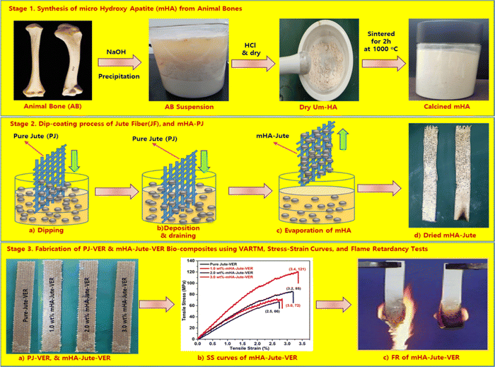 |
| | Fig. 1 (Stage 1) Synthesis of microneedle-hydroxy apatite (mHA); (Stage 2) Dip-coating of mHA on jute fibers; and (Stage 3) Fabrication of mHA-Jute bio-composites through the VARTM method, SS curves and flame tests. | |
2. Experimental
2.1. Materials and characterization
Pure Jute (20 cm × 3 cm) was used as a substrate in this study. A fourier transform-infrared (FT-IR; PerkinElmer, LI600300 Spectrum TWO LiTa, UK) spectrometer was used for the functional group determinations on the pure and mHA-Jute and mHA-Jute-VER bio-composites. Next, a Mastersizer Hydro 2000S (A) (Malvern Instruments Ltd, Malvern, UK) was used for the particle size distribution of mHA particles. On the other hand, a field emission scanning electron microscope EDX (FE-SEM-EDX; TESCAN, LYRA3XM, Czech Republic) at 5–30 kV and a scanning electron microscope (SEM; Emcrafts Cube 2, Korea) at 20 kV were used to identify the elemental analysis and morphologies of the fore-mentioned fibers, respectively. Also, a thermogravimetric analyzer (PerkinElmer STA 6000) was used to know the decomposition stability of the mHA, mHA-Jute, and mHA-Jute-VER bio-composites. The sample weight was taken in the range of 9–12 mg, with a temperature range of 30–700 °C at a rate of 20 °C min−1 in a nitrogen atmosphere.
2.2. Synthesis of in situ mHA by sol–gel method
Firstly, mono-dispersed hydroxy apatite mHA was generated in situ by prolonged treatment of 20% NaOH for 20 days. In particular, 100 g of mHA was dipped in 1 liter of 20 wt% of NaOH solution. Over 20 days, mHA was slowly decomposed and transformed into porous mHA. After 20 days, all the HA had been converted into a powdered slurry that was neutralized with conc. HCl to reach pH ∼ 7. Subsequently, mHA was washed with DI water several times while filtered through a filtration flask. Next, the wet mHA cake was air dried and calcined at 1000 °C for 2 h using a muffle furnace. The calcined mHA was crushed and sieved into micro-powder using a mortar and pestle and sieving tools to obtain mHA powder, in a yield of 95 g, as shown in Fig. 2.
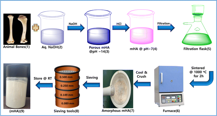 |
| | Fig. 2 Preparation of mHA from raw animal bones via a base–acid-drying method. | |
2.3. Fabrication of pure jute (PJ), and mHA bio-composites
The jute fiber (JF) was treated in 20% NaOH using a solution ratio of 1![[thin space (1/6-em)]](https://www.rsc.org/images/entities/char_2009.gif) :
:![[thin space (1/6-em)]](https://www.rsc.org/images/entities/char_2009.gif) 10 (v
10 (v![[thin space (1/6-em)]](https://www.rsc.org/images/entities/char_2009.gif) :
:![[thin space (1/6-em)]](https://www.rsc.org/images/entities/char_2009.gif) v) during the treatment. The jute fibers were initially soaked in the aqueous solution of NaOH for 15 min. The exposure of jute fibers to NaOH solution disrupts the alkali-sensitive hydroxyl groups, exposing the cellulosic fibrils due to the removal of an amount of lignin, hemicellulose, and waxes covering the jute fibers.26,27 After treatment with NaOH, the JF was completely dried in a hot-air oven for 24 h. Next, JF was dip-coated in a solution of mHA (i.e. 0.5 wt%, 1.0 wt%, 1.5 wt%, 2.0 wt% 2.5 wt%, or 3.0 wt%), washed in DI water and dried. The dip-coating process was repeated five times and mHA-Jute was obtained.
v) during the treatment. The jute fibers were initially soaked in the aqueous solution of NaOH for 15 min. The exposure of jute fibers to NaOH solution disrupts the alkali-sensitive hydroxyl groups, exposing the cellulosic fibrils due to the removal of an amount of lignin, hemicellulose, and waxes covering the jute fibers.26,27 After treatment with NaOH, the JF was completely dried in a hot-air oven for 24 h. Next, JF was dip-coated in a solution of mHA (i.e. 0.5 wt%, 1.0 wt%, 1.5 wt%, 2.0 wt% 2.5 wt%, or 3.0 wt%), washed in DI water and dried. The dip-coating process was repeated five times and mHA-Jute was obtained.
2.4. Development of mHA-Jute-VER bio-composites
The polymer matrix was prepared by mixing 1.0 wt% cobalt naphthalate, and 1.0 wt% MEKP into vinyl ester resin (VER). The VER was uniformly stirred using a mechanical stirrer for 5 min, and then degassed in a vacuum chamber to remove the entangled air bubbles. The bio-composites incorporating mHA-Jute were developed using the hand layup and compression molding process. Bio-composites with a total of 3 layers of PJ and mHA-Jute of size 30 × 20 cm (0.5 wt%, 1.0 wt%, 1.5 wt%, 2.0 wt%, 2.5 wt%, and 3.0 wt% of mHA in JF) were prepared using the vacuum assisted resin transfer molding (VARTM) method. In brief, this is an open-top mold composite part fabricating method that attaches a vacuum bag to the top of the mold tool and applies a vacuum to assist the continuous flow of low-pressure infused vinyl ester resin (VER) from one side of the mold to the other on top of the PJ and mHA-Jute, and cures it in a vacuum oven. The curing process was started at room temperature (RT) for the first 19 min to reach 80 °C. In the second and third stages, the temperature remained constant at 80 °C for 2 h and 120 °C for 3 h, respectively, and then cooled down to RT, as shown in Fig. 3. After cooling, the mHA-Jute bio-composite laminates of 3 mm thickness were taken out of the mold, and were subsequently cut using a cutting machine equipped with a high-speed diamond cutter. The test specimens were cut following the respective testing standards.
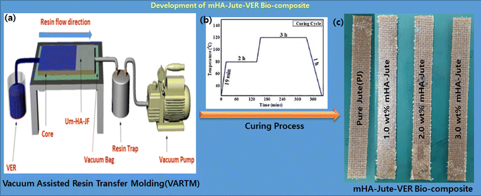 |
| | Fig. 3 Fabrication of mHA-Jute-VER bio-composites via the VARTM technique. | |
2.5. Materials, instruments, and methods
The morphology and elemental analysis of the untreated and treated jute fiber surface were examined using a field emission scanning electron microscope (FE-SEM) (Mira II LMH, Tescan, Germany) equipped with an energy-dispersive detector. Fibers of length 10 mm were cut and pulled out of the woven fabric and pasted on a stub using double-side adhesive carbon tape. Subsequently, the fibers were coated with platinum (Pt) before the FESEM examination. To examine the pure jute and mHA-Jutes, FT-IR spectra were used to determine the functional groups before and after treatment using an FT-IR spectrometer (FT-IR 6300, JASCO, Japan). The FT-IR spectra were recorded in the transmittance mode between the wavelengths of 400 and 4000 cm−1. TGA of untreated and treated jute fibers was performed to determine the change in thermal stability after treatment. The TGA analysis was performed using a thermogravimetric analyzer (STA6000, PerkinElmer, United States). Test specimens weighing 10 mg were heated from 30 °C to 600 °C at a ramp rate of 10 °C min−1, in a nitrogen atmosphere. To determine the flammability characteristics of mHA-Jute-VER bio-composite panels and the JF-VER bio-composite, their heat release rates were determined using a microcalorimeter (FTT0001 MICROCAL, Fire Testing Technology, United Kingdom). PJ and mHA-Jute test specimens weighing 5 mg were tested at a scan rate of 1 °C s−1 in the temperature range of 100 °C to 650 °C. Vertical burning tests were performed as per the UL-94 test standard to examine the flammability of the mHA-Jute-VER bio-composites. Specimens of 150 × 12.7 × 3 mm were prepared and examined as per the testing guidelines. The burning time and burning rate of the developed bio-composites were determined during this examination.
2.6. Mechanical characterization
The bio-composites incorporating mHA-Jute-VER bio-composite panels were mechanically examined using a universal testing machine (UTM-M (RB301), Korea). The tensile tests were performed following ASTM 303 9M-17. Tensile test specimens with a width of 25 mm and a gauge length of 100 mm were tested at a crosshead speed of 2 mm min−1. In order to examine the fracture behavior, the surface morphology of the fractured tensile test specimens was examined using FE-SEM. Three-point bending (flexural) tests of the developed bio-composites were performed in accordance with ASTM D790-17. As per the testing standard, a gauge length equal to 16 times the specimen thickness and a crosshead speed calculated with the expression given in eqn (1) were selected during the flexural tests.| |  | (1) |
where, “R” is the crosshead speed (mm min−1), “L” is the gauge length (mm), “d” is the specimen thickness (mm) and “Z” is the rate of strain, which was taken as 0.01.
Notched izod impact tests were performed in accordance with ASTM D256-10. The impact tests were performed using a low-energy impact tester (QC-639F, Cometech, Korea) equipped with a hammer with a maximum impact energy of 22 J. The impact test specimens of size 12.7 mm in width and 60 mm in length were cut using a high-speed diamond cutter. A V-shaped notch with a notch angle of 45 ± 1°, a notch radius of 0.25 ± 0.05 mm, and a notch depth of 2.54 ± 0.05 mm was cut on the test specimen using a V notch maker (QC-640, Cometech, Korea). A total of three specimens of each type of bio-composite were examined and their mean values (bar graphs) along with standard deviations (error bars) are reported.
3. Results and discussion
3.1. Synthesis of in situ mHA micro particles by sol–gel method, and FT-IR analyses of mHA powder, PJ and mHA-Jute
Mono-dispersed mHA was in situ generated through the chemical reaction of HA from animal bones by prolonged treatment with aq. NaOH through the sol–gel method.16 Consequently, HA was slowly converted into porous mHA and was used to treat pure jute (PJ) by a dip-coating method to produce ion–ion electrolytic chemical interactions of hydroxy (–OH) of PJ, and calcium ion (Ca+2), phosphate ion (–PO43−), carbonate ion (–CO32−), and hydrogen phosphate ion (–HPO42−), of mHA, to form mHA-Jute, as shown in Fig. 4.38
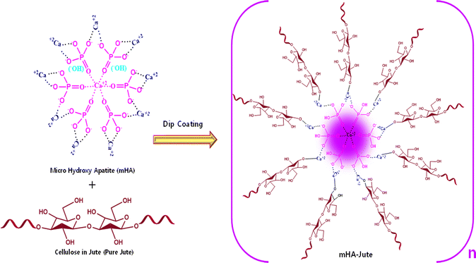 |
| | Fig. 4 Synthesis of mHA-Jute from cellulose in jute and mHA using a dip-coating method through ion–ion electrolytic chemical modification. | |
Fig. 5a shows the FT-IR spectroscopy of mHA micro-needle powder, pure jute, and mHA depositions over pure jute by a dip coating method. The FT-IR spectra of mHA micro-needle powder show the typical functional groups at 3300 cm−1 for –OH, 2942 cm−1 for –CH2, 1650 cm−1 for –CO, 1570 for –CO32−, 1137 cm−1, for C–C, 1044 cm−1 for –PO43−, 890 cm−1 for –HPO42−, and 522 cm−1 for –PO43−. Next, pure jute exhibited peaks at 3440 cm−1 and 2971 cm−1 representing –OH and CH2 bending and stretching frequencies, respectively. The strong absorption peak observed at 1712 cm−1 can be attributed to the presence of C![[double bond, length as m-dash]](https://www.rsc.org/images/entities/char_e001.gif) O groups of acetyl esters in hemicellulose and carbonyl in lignin. The absorption peaks observed at 1029 cm−1 and 1136 cm−1 correspond to the C–O and C–O-C stretching frequencies, respectively, of hemicellulose. After deposition of mHA on the jute fiber (mHA-Jute), the representative FT-IR spectra showed the characteristic peaks of 3435 cm−1, 2933 cm−1, 1723 cm−1, 1570 cm−1, 1058 cm−1, 1142 cm−1, 1047 cm−1, 780 cm−1, and 464 cm−1 for –OH, –CH2, –CO, CO32−, C–O, C–O–C, –PO43−, –HPO42−, and –PO43−, respectively. The characteristic peaks representing micro-needle hemicellulose at 1712 cm−1 and 1135 cm−1 were neither reduced nor merged in mHA-Jute due to deposition of mHA on PJ. On the other hand, significant characteristic hemicellulose peaks were showing in the spectra. In addition, the presence of strong absorption bands was observed at 1570 cm−1, 1047 cm−1, 780 cm−1, and 464 cm−1 in the FT-IR spectra of mHA-Jute, strongly confirming the deposition of mHA on PJ.39 The mHA micro-needle structures were strongly adhered through ionic binding on the surface of PJ to form mHA-Jute to enhance the flame-retardancy property.
O groups of acetyl esters in hemicellulose and carbonyl in lignin. The absorption peaks observed at 1029 cm−1 and 1136 cm−1 correspond to the C–O and C–O-C stretching frequencies, respectively, of hemicellulose. After deposition of mHA on the jute fiber (mHA-Jute), the representative FT-IR spectra showed the characteristic peaks of 3435 cm−1, 2933 cm−1, 1723 cm−1, 1570 cm−1, 1058 cm−1, 1142 cm−1, 1047 cm−1, 780 cm−1, and 464 cm−1 for –OH, –CH2, –CO, CO32−, C–O, C–O–C, –PO43−, –HPO42−, and –PO43−, respectively. The characteristic peaks representing micro-needle hemicellulose at 1712 cm−1 and 1135 cm−1 were neither reduced nor merged in mHA-Jute due to deposition of mHA on PJ. On the other hand, significant characteristic hemicellulose peaks were showing in the spectra. In addition, the presence of strong absorption bands was observed at 1570 cm−1, 1047 cm−1, 780 cm−1, and 464 cm−1 in the FT-IR spectra of mHA-Jute, strongly confirming the deposition of mHA on PJ.39 The mHA micro-needle structures were strongly adhered through ionic binding on the surface of PJ to form mHA-Jute to enhance the flame-retardancy property.
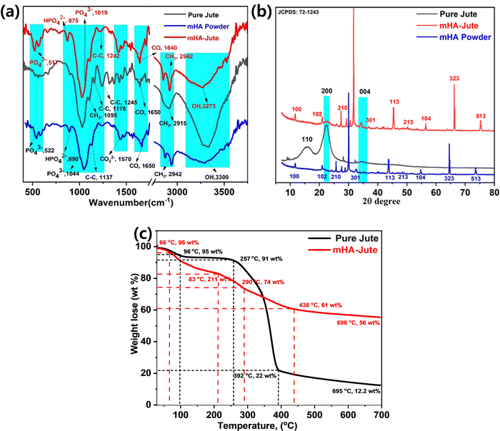 |
| | Fig. 5 (a) FT-IR; (b) XRD of mHA powder, pure jute, and mHA-Jute; (c) thermogravimetric analysis of pure jute, and mHA-Jute. | |
3.2. XRD of mHA powder, pure jute, and mHA-Jute
X-Ray diffraction (XRD) analysis of mHA powder, PJ and mHA-Jute confirmed the crystallinity of PJ, as shown in Fig. 5b. A typical powder XRD pattern of a synthesized mHA powder after thermal treatment at 400 °C for 2 h is presented, where the XRD signals reveal the presence of the crystalline nature of micro-sized HA phases. The XRD signals were found to be consistent with the phases listed in the JCPDS: 72-1243 database and the main signals showed micrometer-sized mHA and 2θ values at 11.76°(100), 30°(102), 26.5°(210), 33°(211), 34°(301), 44°(113), 48°(213), 55°(104), 65°(323), and 74°(513). It can be seen that there are three distinct diffraction peaks that appeared as two broad peaks and a small hump at 2θ values of 15.86°(110) and 22°(200) for the pure crystalline nature and 34.5°(004) for the semi-crystalline nature of the jute fiber, and this is clear evidence of the jute fiber being covered by lignocellulose and hemicellulose, respectively. On the other hand, the XRD signals of mHA-Jute showed similar signals at 2θ values of 11.76°(100), 30°(102), 27.3°(210), 31.7°(211), 34.2°(301), 45.4°(113), 50.2°(213), 56.5°(104), 66.1°(323), and 75.2°(513), respectively. Most of the XRD signals had moved up to 5 units on the scale bar and the signal intensities had changed due to the strong interactions of mHA with JF.40 Besides, the XRD signals at 22°(200) and 34.5°(004) appeared for mHA-Jute, and this confirmed that mHA is strongly glued on the surface of PJ.41 Next, most of the XRD signals were matched to the JCPDS: 72-1243 data chart, which confirmed that mHA are present on the surface of the jute and can affect the crystallinity of mHA-Jute. The results of the XRD analyses obtained in the present investigation are in good agreement with the results reported by Thomas et al.40
3.3. Thermogravimetric analysis of PJ, and mHA-Jute
Thermographs depicting the thermal stability of the jute fibers are shown in Fig. 5c. The thermal degradation of jute fibers was observed to take place in four characteristic steps. The first degradation step was observed due to the loss of moisture with 5 wt% between 35 °C and 96 °C. The second degradation step was observed due to loss of hydroxyl groups with 9 wt% between 96 °C and 257 °C. The third degradation step was perceived as the loss of 78 wt% from 257 °C to 392 °C due to the pyrolysis of the hemicellulose and cellulose present in the JF, respectively. Next, the fourth degradation step was noted from 257 °C to 392 °C due to lignin and other heavy compounds with the loss of 8 wt%. Compared to pure jute fibers, a marginal decline in the thermal stability of mHA-Jute was observed in this region. This decline can be attributed to the presence of mHA within the PJ, which is protected by covalent bonds in the pyrolysis process and forms an active char.21,39 After deposition of mHA on pure jute (mHA-Jute), the thermal stability of mHA-Jute was enormously increased, and the decomposition percentage was reduced and recovered to 44 wt%. The thermal degradation of mHA-Jute was observed to be like that of jute fiber and took place in five characteristic steps. The first degradation step was observed due to the loss of moisture with 5 wt% between 35 °C and 66 °C. The second degradation step was perceived due to loss of hydroxyls and CO2 groups with 17 wt% between 66 °C and 211 °C. The third degradation step was observed with the loss of 16 wt%, from 211 °C to 290 °C due to the pyrolysis of phosphate and carbonate groups deposited on the lignocellulose in the jute fibers, respectively. Next, the fourth degradation step was found with the loss of 39 wt% from 290 °C to 438 °C due to lignin and other heavy compounds. The fifth degradation was observed with retention of 56 wt% of mHA-Jute and loss of 46 wt%, suggesting the thermal stability of inorganic phosphates and carbonates covering the jute fibers. The amount of char formation was observed to increase considerably after the treatment of jute fibers. Compared to the residual char formed after the pyrolysis of pure jute at 392 °C, char formation was observed to increase by 56 wt% for mHA-Jute, and increased char limits the access of oxygen and significantly restricts the fibers from burning.41,42
3.4. SEM-EDX
Fig. 6 shows the FE-SEM, elemental analyses, and wt% of elements present in mHA. The mHA was obtained from animal bone via prolonged treatment with a base (10% NaOH) and mHA possesses higher crystallinity. The mHA shows crystallinity with moderate porosity, and a huge surface area, as shown in Fig. 6a. The mHA can form chemical bonds with surrounding hard tissues such as jute fibers with the formation of an mHA interfacial layer. The similar physical and chemical characteristics of naturally available mHA to those of bone make it biocompatible. Next, elemental analysis mapping showed the presence of Ca, P, and Mg elements, as shown in Fig. 6b.43,44 The map sum spectrum revealed the atomic % of elements which were 73.87% C, 16.49% O, 2.16% Na, 0.12% Mg, 1.23% P, and 2.56% Ca, in the inset image. Kupiec et al. reported the physicochemical properties and morphologies of HA using various synthetic methods.45 The synthesized mHA showed low crystallinity, high porosity, and greater surface area. However, the raw animal bones were slowly decomposed by treatment with NaOH and the mHA recovered as crystalline material presented low amounts of Ca and P elements. These elements showed as ionic bindings within the polymer network. In addition, the EDX analysis showed that the Ca and P functional groups on the surface of mHA can participate further in anchoring the PJ through the dip-coating method and electrostatic interactions.
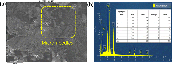 |
| | Fig. 6 (a) SEM morphologies and (b) EDX analysis including wt% of elements present (inset) in mHA powder. | |
3.5. FE-SEM
Fig. 7 shows the surface morphologies of uncoated and mHA-coated jute evaluated using SEM images. Fig. 7a and b present a clean surface of untreated jute and the individual tows appeared very clean and uniform in size. Fig. 7c and d show the surface morphologies of the jute fabric coated with 3.0 wt% mHA. The presence of 3.0 wt% mHA produced a thin (inset yellow box) and continuous coating layer on the jute fibers by the dip-coating deposition of a micro-needle structure of mHA on the jute surface.46 With an increase from 0.5 wt% to 3.0 wt% mHA, a denser distribution of mHA was observed on each individual tow. The rectangular inset images reveal micro-needle deposition with strong ionic interactions with the local fiber network. These ionic depositions were studied by FT-IR analyses (Fig. 1) before and after coating with mHA, as confirmed by their morphologies. This indicated that the post-coated samples with mHA only changed the morphology on the fabrics. However, it was still required to increase the content of fillers to achieve a thicker thermal barrier on fabrics. A thick micro-layered mHA deposition can enhance the thermal insulation on the surface of the jute and can be developed after increasing the mHA content up to 3.0 wt% in the construction. It can be seen that the applied mHA has completely covered the jute fiber mat structures but an air barrier was created on the surface of PJ which can be prone to delamination from the jute fibers.47
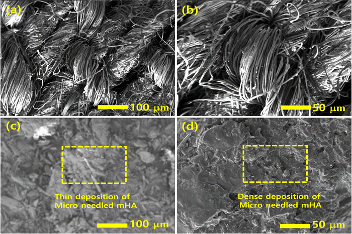 |
| | Fig. 7 The surface morphologies of (a and b) untreated and treated PJ, (c and d) 3.0 wt% of mHA on PJ with dense deposition. | |
3.6. Flammability tests
Fig. 8 shows the flame-retardancy properties of the uncoated and mHA-Jute examined using a vertical flame test, by applying a methane flame to the specimens. The pure jute specimen (Fig. 8a) without mHA coatings; Fig. 8b shows that after exposure to the flame for 5 s, the fibers caught fire; Fig. 8c shows the specimen after exposure for 10 s; and Fig. 8d shows that the mat was completely burning in 15 s. The flame test for 3.0 wt% mHA-Jute is shown with burning times of 0 s, Fig. 8e, 10 s Fig. 8f, 20 s Fig. 8g, and 60 s, Fig. 8h. However, the mHA-coated Jute fibers did not catch the fire at all due to the thermal insulation developed on the fiber network, which provided strong chemical stability to the proposed mHA. The uniform mHA coatings were confirmed by the ionic bonds over the surface of the fibers. In addition, ignition resistance and self-extinguishing capabilities were observed on the mHA-Jute mat with 3.0 wt% mHA-Jute.48 Indoor fire accidents can be prevented by mHA-Jute fabrics and this is a great advantage for indoor applications. Furthermore, it is possible to observe that in the mHA-Jute mats, the combustion area is slightly charred. However, the texture of the mHA-Jute remains same due to the enhanced thermal shielding effect.
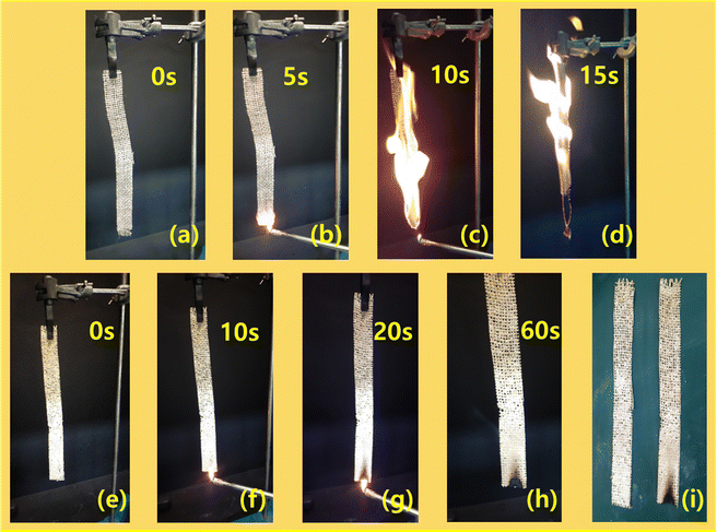 |
| | Fig. 8 Vertical burning tests of mHA-Jute bio-composites. | |
3.7. Micro calorimetry (HRRs)
Micro-calorimetry analyses provided further study of mHA-Jute on PJ compared with a pure jute mat, including peak heat release rate (HRR) and burning rates. Fig. 9 shows the HRR curves of pure jute and mHA-Jute mats (i.e. 0.5 wt%, 1.0 wt%, 1.5 wt%, 2.0 wt% 2.5 wt%, and 3.0 wt%). The HRR values of the pure jute mat are shown to be lower than the mHA-Jute-coated PJ due to the lack of a protection layer formed by mHA-Jute on the jute fibers. This was a serious indication that the ignition trend underwent violent burning along with huge heat release, generating carbonaceous gases and char residue. These inspiring research results showed that the HRR values were decreased after deposition of mHA-Jute and the thermal stability of mHA-Jute composites was enhanced compared to uncoated jute fiber.49
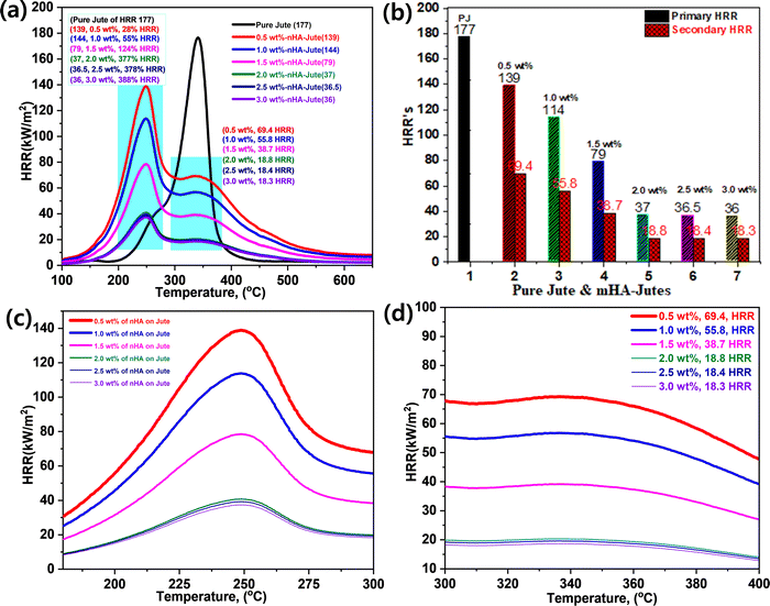 |
| | Fig. 9 (a) Heat release rates (HRRs) of PJ and mHA-Jutes; (b) their HRR percentage increments; (c) primary HRRs; (d) secondary HRRs. | |
Fig. 9a and b show the overall HRR values of JP and mHA-Jute (i.e. 0.5 wt%, 1.0 wt%, 1.5 wt%, 2.0 wt%, 2.5 wt%, and 3.0 wt%), respectively. Pure jute showed an HRR value of 177 and decomposed at 340 °C, whereas mHA-Jute showed two HRR values, which are primary and secondary HRRs compared to PJF. The two HRRs were gradually reduced from 0.5 wt% to 3.0 wt% mHA-Jute. The primary HRRs at 245 °C were attributed to using different wt% of mHA-Jute of 0.5 wt% (139), 1.0 wt% (114), 1.5 wt% (79), 2.0 wt% (37), 2.5 wt% (36.5), and 3.0 wt% (36) compared to the HRR of PJ. Their % increments were 28% for 0.5 wt%, 55% for 1.0 wt%, 134% for 1.5 wt%, 377% for 2.0 wt%, 378% for 2.5 wt%, and 388% for 3.0 wt% mHA deposition on PJ. The numerical values strongly suggested that the saturation point of HRR was achieved by the mHA coatings on PJF, as shown in Fig. 9c. Next, the secondary HRRs of mHA-Jute were shown at 0.5 wt% (69.4), 1.0 wt% (55.8), 1.5 wt% (38.7), 2.0 wt% (18.8), 2.5 wt% (18.4), and 3.0 wt% (18.3), as shown in Fig. 9d. The deposited mHA on host PJ was strongly anchored by the chelation process, and when the deposition wt% of mHA on host PJ increased from 0.5 wt% to 3.0 wt%, the HRR values gradually decreased. We found the saturation point at 3.0 wt% mHA on host PJ. Next, we found two different HRR curves obtained from coated samples. It might be that the decomposition process had been delayed by mHA-Jute during the burning process. As a result, the hydroxyl groups were evaporated first and then carbonaceous groups due to strong thermal blankets from the mHA covering the PJ network. The decomposition and evaporation process will be discussed in the flame-retardancy mechanism section.50
3.8. Fabrication of PJ, and mHA-Jute bio-composites, and their impact energies (IE) and tensile modulus
3.8a. Fabrication of PJ and mHA-Jute.
The PJ and mHA-Jute (i.e. 1.0 wt%, 2.0 wt%, and 3.0 wt% mHA on PJ) bio-composites were prepared using the vacuum assisted resin transfer molding (VARTM) method (Fig. 3). In brief, this is an open-top mold composite part fabricating method that attaches a vacuum bag to the top of the mold tool and applied a vacuum to assist the continuous flow of low-pressure infused vinyl ester resin (VER) from one side of the mold to the other on top of the PJ and mHA-Jute of required dimensions. After completion of the infusion process, the bio-composites were cured according to the method in the literature at various temperatures and cooled, as shown in Fig. 10a.
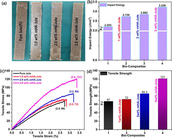 |
| | Fig. 10 (a) Digital images of fabricated PJ and mHA-Jute bio-composites; (b) impact energies (IEs); (c) stress–strain curves and (d) comparison of flexural strengths of mHA-Jute bio-composites against PJ. | |
3.8b. Impact energy (IE).
The impact properties in terms of flexural strength and modulus of the PJ reinforced VER bio-composites are depicted in Fig. 10b. The impact energy of mHA-Jute bio-composites was observed to improve significantly after the incorporation of mHA on the PJ. Compared to PJ, the flexural strength of all mHA-Jute-VER increased from 0.5 wt% to 3.0 wt%, owing to the enhancement of the gluing effect between PJ and mHA. The mHA is dispersed homogeneously in the VER matrix and enhanced the mechanical strength. To determine the mechanical strength, the IE of all the mHA-Jute bio-composites were compared with that of the PJ bio-composite. The IE values were observed to be 2.203 J mm−2 for PJ, 2.689 J mm−2 for 0.5 wt% mHA-Jute-VER, 2.735 J mm−2 for 1.0 wt% mHA-Jute-VER, 2.793 J mm−2 for 1.5 wt% mHA-Jute-VER, 2.852 J mm−2 for 2.0 wt% mHA-Jute-VER, 2.921 J mm−2 for 2.5 wt% mHA-Jute-VER, and 3.229 J mm−2 for 3.0 wt% mHA-Jute-VER. The percentage enhancements in IE observed for mHA-Jute-VER against PJ-VER bio-composite were 22% J.cm−2 for 0.5 wt% mHA-Jute-VER, 24.1% J.cm−2 for 1.0 wt% mHA-Jute-VER, 26.7% J.cm−2 for 1.5 wt% mHA-Jute-VER, 29.4% J.cm−2 for 2.0 wt% mHA-Jute-VER, 32.5% J.cm−2 for 2.5 wt% f mHA-Jute-VER, and 46.5% J.cm−2 for 3.0 wt% mHA-Jute-VER. Therefore, these results showed an enhancement in IE of up to 46.5% compared to the PJ bio-composite, as shown in Fig. 10b, suggesting the improvement in the mechanical strength of the mHA-Jute-VER bio-composites.50
3.8c. Flexural strength (tensile modulus) and comparisons of PJ and mHA-Jute-VER bio-composites.
Fig. 10c depicts the mechanical properties of reinforced PJ and mHA-Jute-VER bio-composites fabricated within vinyl ester resin (VER) using the VARTM method. At the microscale level, the inorganic components of mHA were strongly adhered to the surface of each tow of PJ to enhance the modulus or stiffness due to the good dispersion of mHA within the VER polymer matrix, and strong interactions between mHA-Jute in VER, so good reinforcement can be expected. To demonstrate this reinforcement, typical tensile tests were performed for all mHA-Jute-VER (i.e. 1.0 wt%, 2.0 wt%, and 3.0 wt%) in VER. The results indicated that the PJ was further strengthened by the homogeneous incorporation of mHA at the molecular level. As a result, they exhibited superior mechanical stiffness and strength in comparison to PJ. The flexural strengths of PJ-VER and mHA-PJ-VER panels gradually increased through the chemical bonding process due to the increasing amount of mHA. In particular, the results attributed an enhancement in tensile modulus of 67 MPa for PJ, 72 MPa for 1.0 wt% mHA-Jute-VER, 85.3 MPa for 2.0 wt% mHA-Jute-VER, and 121 MPa for 3.0 wt% mHA-Jute-VER, as shown in Fig. 10d. The percentage enhancements observed for mHA-Jute-VER against PJ-VER bio-composites were 7% MPa for 1.0 wt% mHA-Jute-VER, 27.3% MPa for 2.0 wt% mHA-Jute-VER, and 80.5% MPa for 3.0 wt% mHA-Jute-VER, respectively. Hence, an enhancement in the tensile modulus was suggested to be because of the interfacial bonding between mHA-Jute and VER.51–54
3.8d. Heat release rates (HRR), % HRRs, and limiting oxygen index (LOI).
Fig. 11a shows the HRRS of the flame-retardant property of PJ-VER and mHA-Jute-VER bio-composites, and it was observed mHA-Jute-VER displayed superior intumescent flame-retardant characteristics to the PJ-VER composite. The HRRs were 712 at 416 °C for PJ-VER, 507 at 417 °C for 1.0 wt% mHA-Jute-VER, 311 at 426 °C for 2.0 wt% mHA-Jute-VER, and 190 at 470 °C for 3.0 wt% mHA-Jute-VER. The HRR values were low compared with that of pristine VER. This trend indicated that the ignited neat VER went through violent burning, accompanied by a large release of heat, including a huge amount of exhaust gases such as CO2, CO, and NH3. With its higher thermal conductivity of mHA (i.e. 3500–4000 °C), the novel mHA-Jute-VER bio-composites showed superior HRRs compared to the pure VER panels. When the dopant mHA wt% was increased from 1.0 to 2.0 to 3.0 wt% in VER, the HRRs gradually declined due to the formation of chemical bonds between mHA-Jute and VER, further improving the nucleation density of the HRRs in the VER composite. Fig. 11b shows the higher % HRRs of the mHA-Jute-VER bio-composites with respect to the pure PJV-VER composite. The % HRRs were 41% for 1.0 wt% mHA-Jute-VER, 131% for 2.0 wt% mHA-Jute-VER, and 291% for 3.0 wt% mHA-Jute-VER. The enhancement in the % HRRs strongly suggested that mHA plays an essential role in increasing the integument properties of the proposed novel mHA-Jute-VER bio-composites.49
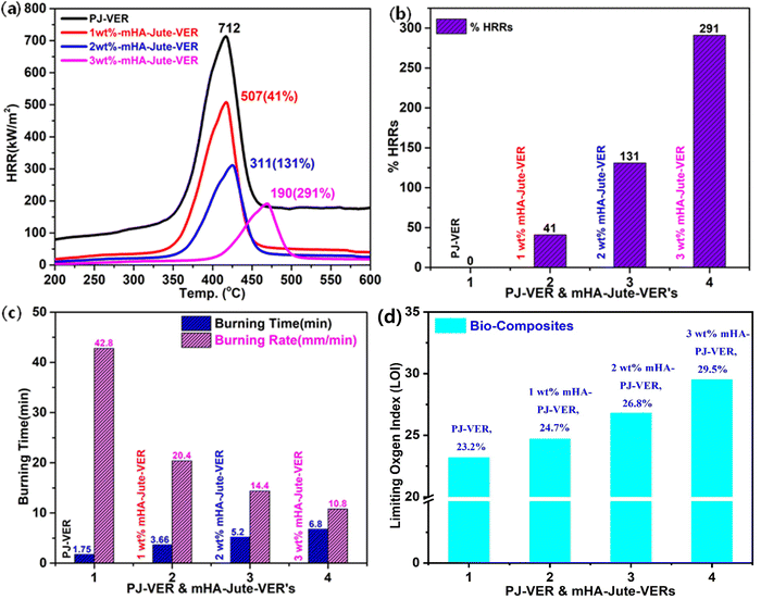 |
| | Fig. 11 (a) HRRs; (b) % HRRs; (c) burning times and burning rates, and (d) LOIs of PJ-VER and mHA-Jute-VER bio-composites. | |
3.8e. Vertical burning tests of PJ-VER and mHA-Jute-VER bio-composites.
To estimate the intumescent flame-retardancy character of the PJ-VER and mHA-Jute-VER bio-composites, vertical burning tests were performed to determine the burning time and burning rates. The PJ-VER bio-composites exhibited longer burning times and lower burning rates owing to the deficiency of flammability by dopant mHA occupying PJ. The mHA is strongly glued on PJ and sandwiched by the VER through ion–ion interactions through chemical bonding. These ionic bonds strongly counteracted the entry of oxygen into mHA-Jute-VER bio-composites. The burning times and burning rates of all mHA-Jute-VER bio-composites are depicted in Fig. 11c. The burning time gradually increased from 6.29 min to 11.2 min and the burning rate gradually decreased from 11.93 to 6.7 from PJ-VER to mHA-Jute-VER bio-composites (i.e. mHA = 1.0 wt%, 2.0 wt%, and 3.0 wt%). These results strongly justified the fact that the novel mHA-Jute-VER bio-composites exhibited significant intumescent flame retardancy compared to the PJ-VER bio-composite.54,55
3.8f. Limiting oxygen indexes (LOIs).
Limiting oxygen indexes (LOIs) of the PJ-VER bio-composite and 1.0 wt%, 2.0 wt% and 3.0 wt% mHA-Jute-VER bio-composites were investigated through LOI and UL-94 tests. The results of the LOI, UL-94 rating and dripping behavior of the PJ-VER blends are summarized in Table 1. It can be seen that pure PJ-VER has a low LOI (23.2) and exhibits high combustion and heavy dripping. LOI values markedly increased to 24.7, 26.7, and 29.5 with the addition of 1.0, 2.0 and 3.0 wt% mHA. The increased LOI values show that burning behavior is restrained during flammation in higher oxygen conditions. mHA promotes the formation of a wrapped carbon layer during the combustion process, subdues the dripping of the PLA matrix and inhibits the transfer of heat and oxygen into the inner substrate, which is the main reason for the higher LOI values.56 The addition of mHA can also diminish the burning times significantly. Neat PJ-VER cannot self-extinguish due to the low melting strength of PJ-VER during combustion, while the UL-94 rating of the PJ-VER blend with 3.0 wt% mHA-PJ-VER reaches the V-0 level, and the dripping behavior is evidently repressed. With the addition of mHA, the dripping of the blends was inhibited. There was no dripping when the amount of mHA was 3%. The results demonstrate that mHA not only has a good effect on the dripping behaviors of PJ-VER blends during combustion but also leads to an enhancement in LOI values at higher flame-retardant concentrations.
Table 1 The LOIs and vertical burning (UL-94) rates of PJ-VER and mHA-PJ-VER bio-composites57
| Bio-composite |
LOI (%) |
UL-94 |
Dripping |
Ignition |
| PJ-VER |
23.2 |
NR |
Yes |
Yes |
| 1% mHA-PJ-VER |
24.7 |
V-1 |
Yes |
Yes |
| 2% mHA-PJ-VER |
26.8 |
V-1 |
Yes |
Yes |
| 3% mHA-PJ-VER |
29.5 |
V-0 |
No |
No |
3.9. SEM analyses of mHA-PJ-VER char residues
After vertical burning tests of the PJ-VER and mHA-Jute-VER bio-composites, we analyzed the char residues using SEM analysis. The char formation revealed the superior stability of the bio-composites, their durability, and maintenance of their texture after burning with respect to the ISO6330 standard. Therefore, the penetrability issue has to be taken into account in the design of mHA flame-retardants and will be resolved in further investigations. After the flame tests, it is mainly possible to observe that PJ-VER within the burning area is moderately charred, and in the case of mHA-Jute-VER the texture of the bio-composite still retains its original structure. Observation of the burnt regions by SEM at higher magnifications of the surface morphologies of PJ-VER and mHA-Jute-VER is demonstrated in Fig. 12. After char tests, the surface morphologies of PJ-VER and mHA-Jute-VER showed dendritic morphologies with a crumpled network due to the removal of carbonaceous gases, as shown in Fig. 12a. On the other hand, the char residues of 1.0 wt% mHA-Jute-VER showed strong condensed networks with regular air cavities, in particular; see Fig. 12b. The 2.0 wt% mHA-Jute-VER showed a loosely glued fiber network due to adhesion of mHA between jute and VER; see Fig. 12c. The 3.0 wt% mHA-Jute-VER showed a dense condensed network with a tightly glued fiber network due to strong adhesion of mHA between individual fibers and VER due to the removal of volatiles, phosphates and the calcium network, as shown in Fig. 12d. After the char tests, the char residues were very crowded due to the concentration being increased from 1.0 wt% to 3.0 wt% mHA, and the simultaneous lessening of the air cavities with the strong deposition of guest mHA on both jute and VER polymer networks. In addition, carbon residues with lattice porous network structures with irregular cavities were observed in the carbon chars. Furthermore, the surface morphology gradually changed with the reduction of pores, which were occupied by mHA-Jute-VER soft microspheres, forming the compact char layer surface. Such a dense build-up is advantageous for insulating heat, and hindering pyrolysis through penetration of oxygen molecules during flame tests, thereby protecting the original environment from secondary combustion tests.58–61
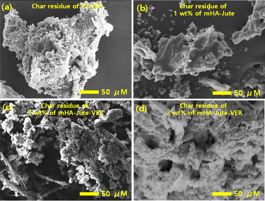 |
| | Fig. 12 The char residues of (a) PJ-VER bio-composites; (b) 1.0 wt%; (c) 2.0 wt%; and (d) 3.0 wt% of mHA-Jute-VER bio-composites. | |
3.10. Flame-retardancy mechanism
The flame-retardancy mechanism of PJ-VER and mHA-Jute-VER bio-composites is depicted in Fig. 13. mHA deposited through ion–ion interactions and the L-B-L method by the dip-coating process provided effective flame retardancy by the condensed vapor phase of the mHA-Jute network. The flame-retardant behavior of mHA showed an incessant, defensive char layer on top of the jute network that can achieve thermal insulation with a mass transport blockade. The heat-protection layer decelerates the seepage of volatile gases generated from the degradation of mHA.62–65 The TGA experiment showed the deterioration rate of mHA-Jute gradually with time. The mechanistic view was that PJ, mHA-PJ, PJ-VER, and mHA-Jute-VER bio-composites were completely burned and formed char remainders, and the subsequent amounts of smoke particles, organic volatiles, and char residues released were investigated, as shown in Fig. 13a and b. Conversely, mHA-treated mHA-PJ and mHA-Jute-VER bio-composites were proposed to be condensed phase phenomena owing to the formation of a thermal shielding barricade of mHA on PJ. The important observation found here is, the mHA is well dispersed in water and strongly deposited on the surface of the PJ network through chemical chelation by Ca2+ and PO4− ions, as shown in Fig. 13c. The solvent blending and mechanical mixing of mHA is strongly stabilized to connect the molecular level interactions and gluing on the surface of jute fibers.35,48 The flammability of the designed mHA-PJ (0.5 wt% to 3.0 wt%) and mHA-Jute-VER bio-composites (1.0 wt% to 3.0 wt%) showed higher flame-retardancy properties than the pure forms due to the continuous and compact char layer on the surface; see Fig. 13d. With the progression of the combustion process, a huge amount of volatile vapors were coming out of the chars which might swell the deposited char layer.26 The volatile gases containing CO2, CO, CH2, NH2, O2, P, Ca and H2, including a considerable number of –OH ions, could be generated in pyrolysis from mHA-PJ (0.5 wt% to 3.0 wt%) and mHA-Jute-VER bio-composites. The amount of pyrolytic gases were released by the charred layers then they are vigorously released to blow out the flames, owing to the reducing effect of the mHA groups and weakening non-flammability effect. Further, the TGA and HRR analyses strongly support the fire-retardancy mechanism of the mHA-PJ (0.5 wt% to 3.0 wt%) and mHA-Jute-VER bio-composites.66–68
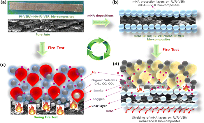 |
| | Fig. 13 The flame retardancy mechanism of (a) PJ; (b) 1.0 wt%; (c) 2.0 wt%; and (d) 3.0 wt% of mHA-Jute-VER bio-composites. | |
3.11. FT-IR, XPS, Raman, and elemental analysis of char residue of 3.0 wt% mHA-PJ-VER bio-composite through flame-retardancy mechanism
Fig. 14 shows the FT-IR, XPS, Raman, and elemental analysis of char residue of the 3.0 wt% PJ-VER bio-composite. FT-IR showed typical functional groups at 3277 cm−1 for –OH, 2945 cm−1 for –CH2, 1642 cm−1 for –CO, 1245 for –C–C–, 1021 cm−1 for –PO43−, 880 cm−1 for –HPO42−, and 520 cm−1 for –PO43−, as shown in Fig. 14a.69 Typical XPS signals periodically appeared at 533.3 eV and 346.9 eV for Ca 2p, and 134 eV for P 2p, due to the appearance of Ca and P groups in the char residue, as shown in Fig. 14b. Next, we found the char residue by Raman analysis and observed that significant representative signals at 1340 cm−1 and 1596 cm−1. Also, the elemental analysis confirmed the presence of C and O as major amounts of 57.8 wt% and 35.2 wt%, and S, P, and Ca as minor amounts of 0.45 wt%, 1.83 wt%, and 4.72 wt%, respectively, as shown in Fig. 14c. Besides, the volatile gases were comprised by CO2, CO, CH2, NH2, O2, P, Ca and H2, including a considerable number of –OH ions, could be generated in the pyrolysis of lignocellulose from mHA-PJ-VER (0.5 wt% to 3.0 wt%) bio-composites. A comprehensive analysis revealed a flame-retardancy mechanism that can manifest P as Ca3(PO4)2 and Ca as CaSO4 as traces in the char residues of mHA-PJ-VER bio-composites, owing to formation of low crystallinity, high porosity, and greater surface area. However, the use of raw animal bones can mean the sluggish decay of crystalline Ca and P elements. Furthermore, these elements have shown ionic binding within the host polymer network. Above and beyond this, EDX analysis of the char residue has shown Ca and P elements which can further contribute in anchoring the host PJ-VER bio-composites in ionic interactions.69,70
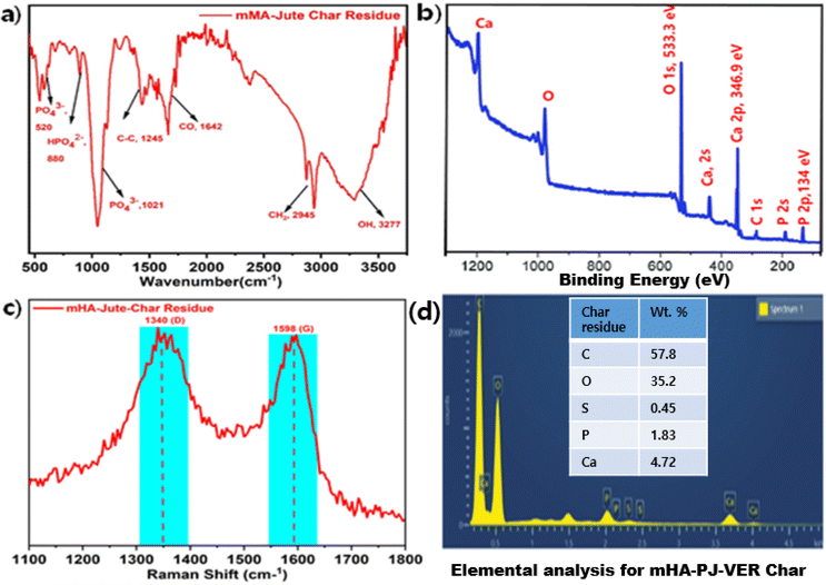 |
| | Fig. 14 (a) FT-IR; (b) XPS; (c) Raman; (d) elemental analyses of 3.0 wt% mHA-Jute-VER bio-composite char. | |
4. Conclusions
In these research findings, a novel dip-coating process for fiber surface modification of lignocellulosic fibers prior to their incorporation into vinyl-ester-based bio-composites was experimentally explored. PJ was treated with a solution of NaOH. mHA was prepared using the phosphate decomposition method by base–acid treatment and a dip-coating method applied to deposit it on PJ to obtain mHA-Jute. The FE-SEM, EDX, and FT-IR analyses of the treated PJ surface confirmed the deposition of mHA on the surface of PJ. The doping of PJ with mHA significantly improved its flame-retardancy property as a reduction of more than 86% in HRR was observed after the treatment. The mHA-JF-VER bio-composites developed using the VARTM technique incorporating jute fibers treated with (0.5 wt%, 1.0 wt%, 1.5 wt%, 2.0 wt%, 2.5 wt%, and 3.0 wt%) mHA in VER exhibited optimum tensile and flexural properties. These properties were observed to gradually improve from 0.5 wt% to 3.0 wt% mHA-JF-VER bio-composites. This phenomenon was attributed to an increase in the strength of the jute fibers exposed to mHA wt%. The impact strength of the bio-composites was observed to gradually increase with increasing treatment concentration. The fractography of failed tensile and impact test specimens exhibited an improvement in the interfacial bonding between the treated jute fibers and the VER matrix. The flammability characteristics were examined by vertical burning tests (UL-94, vertical burning test). Hence, it can be further concluded that the proposed mHA-JF and mHA-JF-VER bio-composites not only improve the flame retardancy of the fibers and the bio-composites incorporating them but also improve the tensile and flexural properties of the bio-composites.
Conflicts of interest
There are no conflicts to declare.
Acknowledgements
This work was supported by the National Research Foundation of Korea (NRF) grant funded by the Korean Government (MSIP) No. 2018R1A6A1A03024509, and 2019R1A2C1011113.
References
- F. Vilaplana, E. Strömberg and S. Karlsson, Polym. Degrad. Stab., 2010, 95, 2147–2161 CrossRef CAS.
- S. M. Khoshnava, R. Rostami, M. Ismail, A. R. Rahmat and B. E. Ogunbode, Constr. Build. Mater., 2017, 154, 155–166 CrossRef CAS.
- F. Ahmad, H. S. Choi and M. K. Park, Macromol. Mater. Eng., 2015, 300, 10–24 CrossRef CAS.
- S. K. Ramamoorthy and M. Skrifvars, Polym. Rev., 2015, 55, 107–162 CrossRef CAS.
- V. K. Thakur, M. K. Thakur and R. K. Gupta, Int. J. Polym. Anal. Charact., 2014, 19, 256–271 CrossRef CAS.
- S. Chaitanya and I. Singh, Mater. Manuf. Processes, 2017, 2, 468–474 CrossRef.
- P. K. Bajpai, I. Singh and J. Madaan, J. Reinf. Plast. Compos., 2012, 31, 1712–1724 CrossRef CAS.
- S. Chaitanya, I. Singh and J. I. Song, Composites, Part B, 2019, 173, 106895 CrossRef.
- O. Akampumuza, P. M. Wambua, A. Ahmed, W. Li and X. Qin, Polym. Compos., 2017, 38, 2553–2569 CrossRef CAS.
- U. K. Komal, M. K. Lila and I. Singh, Composites, Part B, 2020, 180, 107535 CrossRef CAS.
- S. Chaitanya and I. Singh, International Journal of Precision Engineering and Manufacturing-Green Technology, 2018, 5, 143–150 CrossRef.
- Y. Zhang, R. Peng, G. Zhou, Z. Fang and X. Li, Chin. J. Polym. Sci., 2015, 33, 1683–1690 CrossRef CAS.
- U. G. K. Wegst, H. Bai, E. Saiz, A. P. Tomsia and R. O. Ritchie, Nat. Mater., 2015, 14, 23–36 CrossRef CAS PubMed.
- F. Chen, P. Huang, Y. J. Zhu, J. Wu, C. L. Zhang and D. X. Cui, Biomaterials, 2011, 32, 9031–9039 CrossRef CAS PubMed.
- F. Chen and Y. J. Zhu, Curr. Nanosci., 2014, 10, 465–485 CrossRef CAS.
- H. Liu, H. Peng, Y. Wu, C. Zhang, Y. Cai, G. Xu, Q. Li, X. Chen, J. Ji, Y. Zhang and H. W. OuYang, Biomaterials, 2013, 34, 4404–4417 CrossRef CAS PubMed.
- Y. Wen, M. Wu, M. Zhang, C. Li and G. Shi, Adv. Mater., 2017, 29, 1702831 CrossRef PubMed.
- M. Schonhoff, Curr. Opin. Colloid Interface Sci., 2003, 8, 86–95 CrossRef CAS.
- S. Bourbigot, M. L. Bras, S. Duquesne and M. Rochery, Macromol. Mater. Eng., 2004, 289, 499–511 CrossRef CAS.
- Y. C. Li, S. Mannen, A. B. Morgan, S. Chang, Y. H. Yang, B. Condon and J. C. Grunlan, Adv. Mater., 2011, 23, 3926–3931 CrossRef CAS PubMed.
- H. Li, D. B. Wu, J. Wu, L. Y. Dong, Y. J. Zhu and X. L. Hu, Adv. Mater., 2017, 29, 1703548 CrossRef PubMed.
- S. S. Ugur, M. Sarıışık, A. H. Aktaş, M. Ç. Uçar and E. Erden, Nanoscale Res. Lett., 2010, 5, 1204–1210 CrossRef CAS.
- N. F. Attia, E. S. Goda, M. A. Nour, M. W. Sabaa and M. A. Hassan, Mater. Chem. Phys., 2015, 168, 147–158 CrossRef CAS.
- N. F. Attia, J. Therm. Anal. Calorim., 2022, 147, 5733–5742 CrossRef CAS.
- N. F. Attia, S. E. A. Elashery, A. M. Zakria, A. S. Eltaweil and H. Oh, Mater. Sci. Eng., B, 2021, 274, 115460 CrossRef CAS.
- N. F. Attia, A. A. E. Ebissy and M. A. Hassan, Polym. Adv. Technol., 2015, 26, 1551–1557 CrossRef CAS.
- A. El-Shafei, M. Elshemy and A. Abou-Okeil, Carbohydr. Polym., 2015, 118, 83–90 CrossRef CAS PubMed.
- S. Baseri, M. Karimi and M. Morshed, Fibers Polym., 2014, 15, 161–168 CrossRef CAS.
- F. Rault, S. Giraud, F. Salaün and X. Almeras, Polymers, 2015, 7, 220–234 CrossRef.
- F. Carosio, G. Laufer, J. Alongi, G. Camino and J. C. Grunlan, Polym. Degrad. Stab., 2011, 96, 745–750 CrossRef CAS.
- P. S. Dhumal, M. A. Bhakare, K. D. Lokhande, M. P. Bondarde and S. Surajit, Cellulose, 2022, 29, 8879–8888 CrossRef CAS.
- K. S. Chavali, D. A. Pethsangave, K. C. Patankar, R. V. Khose, P. H. Wadekar, S. Maiti, R. V. Adivarekar and S. Some, J. Mater. Sci., 2020, 55, 14197–14210 CrossRef CAS.
- T. Ma, L. Li, M. Pan, C. Guo and C. Mei, Composites, Part A, 2022, 162, 107142 CrossRef CAS.
- M. A. Bhakare, K. D. Lokhande, M. P. Bondarde, P. S. Dhumal and S. Some, Chem. Eng. J., 2023, 454, 140421 CrossRef CAS.
- Z. Xu, J. Zhan, Z. Xu, L. Mao, X. Mu and R. Tao, Molecules, 2022, 27, 8783 CrossRef CAS PubMed.
- S. Ji, H. Duan, Y. Chen, D. Guo and H. Ma, Polymer, 2020, 207, 122917 CrossRef CAS.
- S. Chaitanya, R. K. Chidarala and J. I. Song, Composites, Part B, 2020, 197, 108154 CrossRef CAS.
- R. K. Cheedarala and J. I. Song, Mater. Adv., 2021, 2, 497–510 RSC.
- R. K. Cheedarala, M. N. Prabhakar, B. G. Cho, Y. Park and J. I. Song, Mater. Adv., 2021, 2, 4339–4351 RSC.
- M. G. Thomas, E. Abraham, P. Jyotishkumar, H. J. Maria, L. A. Pothen and S. Thomas, Int. J. Biol. Macromol., 2015, 81, 768–777 CrossRef CAS PubMed.
- V. C. Kadapa, R. K. Cheedarala and J. I. Song, J. Appl. Polym. Sci., 2021, 138, e50227 CrossRef.
-
S. J. Park, R. K. Cheedrala, M. S. Diallo, C. Kim, I. S. Kim and W. A. Goddard III, Nanotechnology for Sustainable Development, Springer, Cham, 2012 Search PubMed.
- R. K. Cheedarala, E. J. Park, K. G. Kong, Y. B. Park and H. W. Park, Int. J. Heat Mass Transfer, 2016, 100, 396–406 CrossRef CAS.
- R. K. Cheedarala and J. I. Song, Int. J. Heat Mass Transfer, 2020, 162, 120391 CrossRef CAS.
- R. K. Cheedarala and J. I. Song, RSC Adv., 2019, 9, 31735–31746 RSC.
- R. K. Cheedarala, J. J. Jeon, C. D. Kee and I. K. Oh, Adv. Funct. Mater., 2014, 24, 6005–6015 CrossRef CAS.
- A. S. Kupiec, R. Kijkowska, D. Malina and Z. Wzorek, Dig. J. Nanomater. Bios., 2012, 7, 385–391 Search PubMed.
- J. J. Jeon, R. K. Cheedarala, C. D. Kee and I. K. Oh, Adv. Funct. Mater., 2013, 23, 6007–6018 CrossRef CAS.
- F. F. Chen, Y.-J. Zhu, F. Chen, L.-Y. Dong, R.-L. Yang and Z.-C. Xiong, ACS Nano, 2018, 12, 3159–3171 CrossRef CAS PubMed.
- R. K. Cheedarala, K. V. Chalapathi and J. I. Song, Chem. Eng. J. Adv., 2021, 8, 100164 CrossRef CAS.
- R. K. Cheedarala and J. I. Song, Sci. Rep., 2022, 12, 3879 CrossRef CAS PubMed.
- K. V. Chalapathi, J. I. Song and M. N. Prabhakar, J. Nat. Fibers, 2022, 19, 2129–2139 CrossRef CAS.
- R. K. Cheedarala, G. H. Kim, S. Cho, J. Lee, J. Kim, H. K. Song, J. Y. Kim and C. Yang, J. Mater. Chem., 2011, 21, 843–850 RSC.
- R. K. Cheedarala, L. C. Duy and K. K. Ahn, Nano Energy, 2018, 44, 430–437 CrossRef CAS.
- R. K. Cheedarala, A. N. Parvez and K. K. Ahn, Nano Energy, 2018, 53, 362–372 CrossRef CAS.
- K. Kong, R. K. Cheedarala, M. Kim, H. D. Roh, Y. B. Park and H. W. Park, Composites, Part A, 2016, 85, 103–112 CrossRef CAS.
- S. Kamarian, R. Yu and J. I. Song, Nanotechnol. Rev., 2022, 11, 252–265 CrossRef CAS.
- R. Yu, M. N. Prabhakar, D. W. Lee and J. I. Song, J. Nat. Fibers, 2021, 1–11 CAS.
- R. Yu, M. N. Prabhakar and J. I. Song, J. Polym. Environ., 2022, 30, 5313–5326 CrossRef CAS.
- R. K. Cheedarala and J. I. Song, Sci. Rep., 2022, 12, 3700 CrossRef CAS PubMed.
- R. R. Chidambaram, I. Kopparapu, A. Raykar, A. Kulkarani, A. V. V. Sankar, S. Ayyanar, A. Nagarjuna and R. K. Cheedarala, Results Eng., 2022, 16, 100652 CrossRef.
- M. A. Malik, R. Surepally, N. Akula, R. K. Cheedarala, A. A. Alshehri and K. A. Alzahrani, Catalysts, 2023, 13, 55 CrossRef CAS.
- R. K. Cheedarala, V. Sunkara and J. W. Park, Syn. Com., 2008, 39, 1966–1980 CrossRef.
- R. K. Cheedarala and J. I. Song, Front. Nanotechnol., 2021, 3, 667453 CrossRef.
-
R. K. Cheedarala, Novel Nanomaterials (a book chapter), Intech Open, London, 2021 Search PubMed.
- S. Gaikwad, R. K. Cheedarala, R. Gaikwad, S. Kim and S. Han, Appl. Sci., 2021, 11, 9856 CrossRef CAS.
- S. A. Nahian, R. K. Cheedarala and K. K. Ahn, Nano Energy, 2017, 38, 447–456 CrossRef CAS.
- R. K. Cheedarala, E. J. Park, Y. B. Park and H. W. Park, Phy. Status. Solidi. A, 2015, 212, 1756–1766 CrossRef CAS.
- R. K. Cheedarala and J. I. Song, Int. J. Smart and Nano Mat., 2020, 11, 38–46 CrossRef.
- R. K. Cheedarala and J. I. Song, J. Mech. Eng. Autom., 2019, 9, 225–229 Search PubMed.
|
| This journal is © The Royal Society of Chemistry 2023 |
Click here to see how this site uses Cookies. View our privacy policy here.  Open Access Article
 *,
Ruiwen
Yu
and
Jung
Il Song
*
![[thin space (1/6-em)]](https://www.rsc.org/images/entities/char_2009.gif) :
:![[thin space (1/6-em)]](https://www.rsc.org/images/entities/char_2009.gif) 10 (v
10 (v![[thin space (1/6-em)]](https://www.rsc.org/images/entities/char_2009.gif) :
:![[thin space (1/6-em)]](https://www.rsc.org/images/entities/char_2009.gif) v) during the treatment. The jute fibers were initially soaked in the aqueous solution of NaOH for 15 min. The exposure of jute fibers to NaOH solution disrupts the alkali-sensitive hydroxyl groups, exposing the cellulosic fibrils due to the removal of an amount of lignin, hemicellulose, and waxes covering the jute fibers.26,27 After treatment with NaOH, the JF was completely dried in a hot-air oven for 24 h. Next, JF was dip-coated in a solution of mHA (i.e. 0.5 wt%, 1.0 wt%, 1.5 wt%, 2.0 wt% 2.5 wt%, or 3.0 wt%), washed in DI water and dried. The dip-coating process was repeated five times and mHA-Jute was obtained.
v) during the treatment. The jute fibers were initially soaked in the aqueous solution of NaOH for 15 min. The exposure of jute fibers to NaOH solution disrupts the alkali-sensitive hydroxyl groups, exposing the cellulosic fibrils due to the removal of an amount of lignin, hemicellulose, and waxes covering the jute fibers.26,27 After treatment with NaOH, the JF was completely dried in a hot-air oven for 24 h. Next, JF was dip-coated in a solution of mHA (i.e. 0.5 wt%, 1.0 wt%, 1.5 wt%, 2.0 wt% 2.5 wt%, or 3.0 wt%), washed in DI water and dried. The dip-coating process was repeated five times and mHA-Jute was obtained.


![[double bond, length as m-dash]](https://www.rsc.org/images/entities/char_e001.gif) O groups of acetyl esters in hemicellulose and carbonyl in lignin. The absorption peaks observed at 1029 cm−1 and 1136 cm−1 correspond to the C–O and C–O-C stretching frequencies, respectively, of hemicellulose. After deposition of mHA on the jute fiber (mHA-Jute), the representative FT-IR spectra showed the characteristic peaks of 3435 cm−1, 2933 cm−1, 1723 cm−1, 1570 cm−1, 1058 cm−1, 1142 cm−1, 1047 cm−1, 780 cm−1, and 464 cm−1 for –OH, –CH2, –CO, CO32−, C–O, C–O–C, –PO43−, –HPO42−, and –PO43−, respectively. The characteristic peaks representing micro-needle hemicellulose at 1712 cm−1 and 1135 cm−1 were neither reduced nor merged in mHA-Jute due to deposition of mHA on PJ. On the other hand, significant characteristic hemicellulose peaks were showing in the spectra. In addition, the presence of strong absorption bands was observed at 1570 cm−1, 1047 cm−1, 780 cm−1, and 464 cm−1 in the FT-IR spectra of mHA-Jute, strongly confirming the deposition of mHA on PJ.39 The mHA micro-needle structures were strongly adhered through ionic binding on the surface of PJ to form mHA-Jute to enhance the flame-retardancy property.
O groups of acetyl esters in hemicellulose and carbonyl in lignin. The absorption peaks observed at 1029 cm−1 and 1136 cm−1 correspond to the C–O and C–O-C stretching frequencies, respectively, of hemicellulose. After deposition of mHA on the jute fiber (mHA-Jute), the representative FT-IR spectra showed the characteristic peaks of 3435 cm−1, 2933 cm−1, 1723 cm−1, 1570 cm−1, 1058 cm−1, 1142 cm−1, 1047 cm−1, 780 cm−1, and 464 cm−1 for –OH, –CH2, –CO, CO32−, C–O, C–O–C, –PO43−, –HPO42−, and –PO43−, respectively. The characteristic peaks representing micro-needle hemicellulose at 1712 cm−1 and 1135 cm−1 were neither reduced nor merged in mHA-Jute due to deposition of mHA on PJ. On the other hand, significant characteristic hemicellulose peaks were showing in the spectra. In addition, the presence of strong absorption bands was observed at 1570 cm−1, 1047 cm−1, 780 cm−1, and 464 cm−1 in the FT-IR spectra of mHA-Jute, strongly confirming the deposition of mHA on PJ.39 The mHA micro-needle structures were strongly adhered through ionic binding on the surface of PJ to form mHA-Jute to enhance the flame-retardancy property.


