
 Open Access Article
 This Open Access Article is licensed under a Creative Commons Attribution-Non Commercial 3.0 Unported Licence
Design and synthesis of a terrylene diimide-based stable cyan dye for printable electrofluidic display†
Yong
Deng‡
ac,
Yuanyuan
Guo‡
 b,
Dechao
Ye
ac,
Wangqiao
Chen
*b and
Guofu
Zhou
*b
b,
Dechao
Ye
ac,
Wangqiao
Chen
*b and
Guofu
Zhou
*b
aAcademy of Shenzhen Guohua Optoelectronics, Shenzhen 518110, P. R. China
bGuangdong Provincial Key Laboratory of Optical Information Materials and Technology & Institute of Electronic Paper Displays, South China Academy of Advanced Optoelectronics, South China Normal University, Guangzhou 510006, P. R. China. E-mail: wqchen@m.scnu.edu.cn; guofu.zhou@m.scnu.edu.cn
cShenzhen Guohua Optoelectronics Tech. Co. Ltd, Shenzhen 518110, P. R. China
First published on 15th June 2023
Abstract
Electrofluidic displays (EFDs) have undergone significant advancement recently due to their many advantages, including reflective mode, fast response, and excellent optical performance. The design and synthesis of suitable cyan, magenta, and yellow (CMY) dye for the oil layer is a basic premise for display operation. Compared with magenta and yellow dye, the development of cyan dye is more difficult due to its much red-shifted absorption, which requires choosing a more elongated backbone and further solving the solubility and stability issues. In this work, we synthesized a terrylene diimide (TDI)-based cyan dye TDIC and used it for the oil layer in the EFD. It exhibited excellent device performance with an extraordinarily high molar absorption coefficient up to 65![[thin space (1/6-em)]](https://www.rsc.org/images/entities/char_2009.gif) 000 L moL−1 cm−1, high optical stability, and fast response. Eventually, we realized the inkjet printing process of TDIC for the fabrication EFD devices, which is conducive to the industrialization of the EFD display.
000 L moL−1 cm−1, high optical stability, and fast response. Eventually, we realized the inkjet printing process of TDIC for the fabrication EFD devices, which is conducive to the industrialization of the EFD display.
Introduction
Due to the many advantages of visual health (using ambient light),1 low energy consumption, fast response time (switching time <20 ms),2 superb optical performance (white state reflectance up to 50%),3,4 as well as the potential application for flexible devices, electrofluidic display (EFD) with reflective mode has received extensive study as an emerging display technology.5–8 In addition, EFD may make a breakthrough for the two technical bottlenecks of “full color” and “video play”, which currently restrict the application of electronic paper displays.As shown in Fig. 1, a basic EFD pixel architecture contains several parts, including the bottom ITO substrate, hydrophobic layer, dielectric layer, oil layer, polar liquid layer, ITO top plate, as well as pixel wall. When there is no electric field, the oil layer spread over the hydrophobic layer and the device stays in the “off” state, showing the oil color. When a voltage is applied, the oil layer shrinks into the corner of the pixels and the device changes to the “on” state. In this case, the ambient light reflects from the external white reflector.
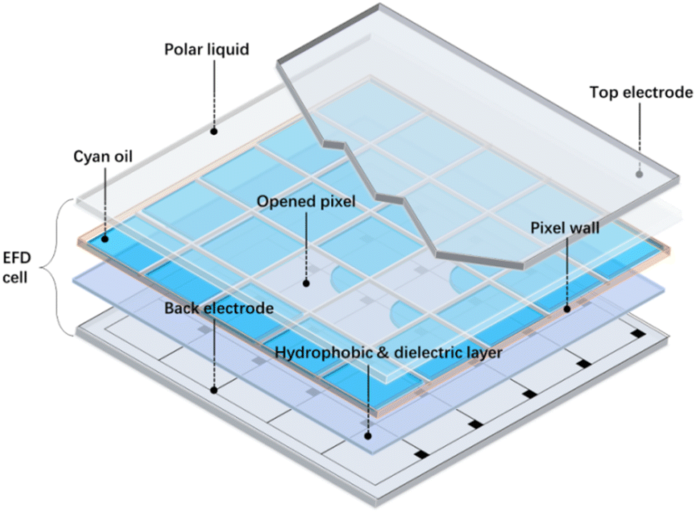 | ||
| Fig. 1 Schematic drawing of the EFD cell structure. | ||
The hydrophobic layer materials,9 polar liquid components,10,11 as well as pixel wall12 can all affect the “on” and “off” states of the pixel, and the corresponding materials have been studied extensively by researchers. Aside from the abovementioned several factors, the oil layer also plays a vital role in determining not only the direct display effect, such as the brightness of color, accuracy of color coordinates, lifetime of the display but also many other device parameters, such the driving voltage, opening ratio, and flow time. Therefore, an ideal dye suitable for the oil layer should fulfill several requirements, including sufficient solubility in the nonpolar solvent (e.g., dodecane), low viscosity (reducing the amplitude of the driving voltage or switching speed), high molar absorption coefficient (increasing the contrast ratio of the pixel), high symmetric structure (preventing generation of molecular polarization), and high stability under the irradiation of the sunlight.
Toward this goal, several papers and patents referring to the new electrofluidic dyes have been published, including phthalocyanine dyes,13 anthraquinone dyes,14–16 azo dyes,16–21 and perylene diimides (PDI) dyes.22 Among all the dyes with different colors, developing the three primary colors cyan, magenta, and yellow (CMY) is a relatively more important task, especially for a full-color EFD display that contains three separated stacking CMY layers.23 When the three CMY layers are all in the “off” state, the CMY oil layer will spread over the hydrophobic layer, and the combination of the CMY color will be black. Similarly, when one of the CMY layers is in the “on” state, the combination color of the other two dyes will form red (M + Y), green (C + Y), or blue (C + M) subsequently. In this case, theoretically, the device can form various colors, which is favorable for video play.
As a matter of fact, researchers have developed several suitable CMY dyes for EFD usage based on azo dyes21,24 and phthalocyanine dyes.13 Nevertheless, compared with yellow and magenta dyes, developing cyan dye is relatively more challenging due to the much red-shifted absorption for cyan dyes. To achieve this goal, generally, a large conjugated backbone needs to be introduced into the cyan dyes, and this will bring several issues, such as long synthetic steps, low solubility, and decreased molecular stability. Previously, our group tested a cyan dye based on phthalocyanine dye but with fast ‘flow back’ behavior, which may be due to the metal atom at the center of the molecule. Organic perylene dyes have good color saturation, excellent photo-stability, and are widely used as acceptor materials in organic solar cells.25–27 Recently, our group also reported a series of dyes based on the PDI backbone and all these dyes exhibited rather good device stability under sunlight.22 Following this work, we hypothesized that if the PDI conjugated backbone was further elongated, the absorption of the target dyes will redshift again and possibly satisfactory cyan dyes will be obtained through this strategy. In this work, we synthesized a new cyan dye TDIC based on terrylene diimides and found out that it had an extraordinarily high molar absorption coefficient up to 65000 L mol−1 cm−1 and high optical stability. In addition, device testing demonstrated that this dye showed excellent device performance, including low driving voltage, large opening ratio, and good flow back behavior. In addition, with appropriate viscosity and surface tension, TDIC can be fabricated in EFD devices through the inject printing process, indicating that TDIC is a potential candidate cyan dye for commercial EFD usage in the future.
Results and discussion
The synthetic route for cyan dye TDIC was shown in Scheme 1. Following the reported literature,19,28 naphthalene tetracarboxylic anhydride (NDA) underwent decarbonylation and bromination reaction successively under the condition of KOH and Br2 to give compound 1, which can be further converted into compound 2 after reacting with alkyl amine. Compound 2 and 1,4-bis(4,4,5,5-tetramethyl-1,3,2-dioxaborolan-2-yl)naphthalene (3) reacted using the Pd catalyst to form the critical terrylene diimide intermediate TDI-C8C12.29 After bromination and the introduction of alkyl phenol, the target molecule TDIC can be obtained.30,31 The 1H NMR is shown in Fig. 2. The integral of two singlet peaks in 9.37 ppm and 8.16 ppm is 4H and 4H, which can be ascribed to the total 8H in the terrylene backbone, while the integral of two doublet peaks in 7.41 ppm and 7.07 ppm is 8H and 8H, respectively, which can be attributed to the total 16H from the four phenyl group. All these signals demonstrated the successful introduction of the alkyl phenoxyl group. In addition, the structure was further confirmed through 13C NMR and MS spectra, as shown in Fig. S1–S7 (ESI†). For the EFD dye, high solubility in a nonpolar solvent is essential for the EFD application; using the previous method,24 the maximum solubility of TDIC in decane is up to 20%.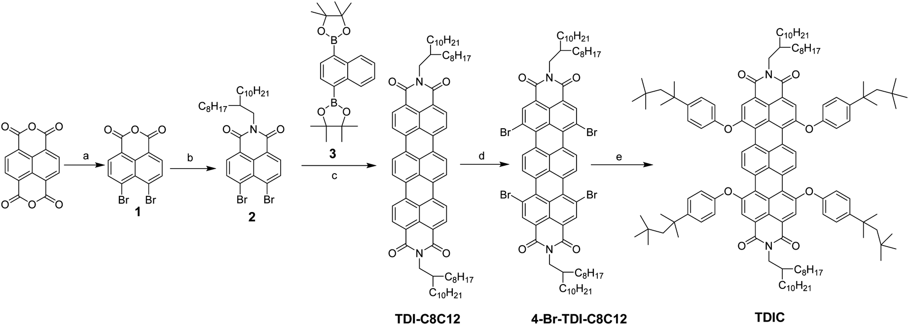 | ||
| Scheme 1 Synthetic route for TDIC: (a) KOH, Br2, H2O, 85 °C, 96%; (b) 2-octyldodecylamine, THF/propionic acid, 60 °C, 55%; (c) Pd2(dba)3, Pcy3, K2CO3, anhydrous o-xylene, 145 °C, 30%; (d) Br2, K2CO3, 1.2-dichloroethane, 60 °C, 90%; (e) p-octylphenol, Cs2CO3, toluene/DMF, 120 °C, 72%. | ||
 | ||
| Fig. 2 1H NMR spectrum of TDIC. | ||
The UV-vis absorption spectrum was measured, as shown in Fig. 3a. TDIC shows main absorption between 550 nm and 700 nm with the lowest energy λmax of 654 nm and a shoulder peak at 612 nm, which can be ascribed to the S0–S1 and S0–S2 transition, respectively. The optical band gap Egopt was calculated to be 1.78 eV from the equation Egopt = 1240 nm/λonset (698 nm). For EFD, a good contrast ratio is important for a good viewing effect for readers, and the contrast ratio is directly related to the molar absorption efficiency (ε) of the dye. The higher the value of ε, the higher the contrast ratio for the EFD. Hence, we also measured the UV-vis absorption of the TDIC at three different concentrations (1.6 × 10⁻⁶, 3.2 × 10⁻⁶, and 4.8 × 10⁻⁶ mol L−1) and calculated its ε. As shown in Fig. 3b, the value of ε is as high as 64876 L mol−1 cm−1, which is among the highest values for cyan dye, to the best of our knowledge.
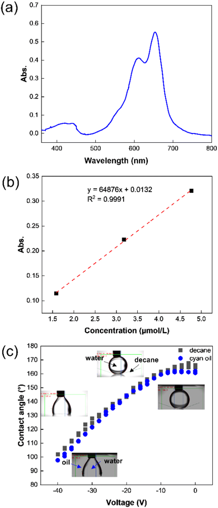 | ||
| Fig. 3 (a) The UV-vis adsorption spectrum of cyan oil (8.2 × 10⁻⁶ M); (b) the molar extinction coefficient was 64876 L mol−1 cm−1; (c) the electrowetting curve of DI water drop in decane and cyan oil. | ||
The colored oil is the main component of the display color in the EFD device, and the oil layer plays the role of an optical switch. Therefore, the optical and electrical stability of the oil layer is the key to realizing the EFD. Guo et al. studied the effect of the dyes on the electrowetting behavior, and they found that dye molecules with tertiary amino groups would be protonated and charged at the oil–water interface under an electric field, resulting in an asymmetry in the electrowetting behavior.32 Similarly, Li et al. also found and proved that dye molecules with tertiary amine structures can be protonated, which caused the pH value of water to increase.33 In addition, Guo et al. also revealed that the conductivity of oil would also affect the stability of EFD devices, and oils with high conductivity cannot maintain a shrinkage state under a continuous DC electric field, which in turn affects the opening rate of the EFD cells.34 Differently, TDIC has a larger conjugate and structurally symmetrical structure with no functional groups that can be protonated; hence, TDIC should more stable under an electrical field. For the verification of electrical stability, the electrical wetting curve of water in TDIC oil was examined. Fig. 3c showed the contact angle change of DI water drop in decane and cyan oil. Without voltage, the initial contact angle of the water droplet on the fluoropolymer surface under decane and cyan oil was above 160°. An average of 3 measurements was taken for drawing the electrowetting curve. Compared to the electrowetting curve of DI water in pure decane, the water drop contact angle in cyan oil changed from 160° to 96°, when the voltage increased from 0 V to −40 V. The change in the contact angle was slightly larger than in pure decane, and the contact angle hysteresis was less than 3°. For cyan oil, due to the lower light transmittance than pure decane, the measurement error might be slightly larger. The reversible contact angle change indicated that the cyan dye oil has excellent chemical stability under an electric field, which is crucial for EFD devices.
The electrochemical property of TDIC was further studied by cyclic voltammetry (CV), and the CV curve is shown in Fig. 4. For TDIC, the first reduction potential is −0.68 V vs. Ag/AgCl reference electrode; hence, the onset of the reduction potential (Eonsetred) versus FeCp2+/0 (+0.53 V vs. Ag/AgCl, Fig. S8, ESI†) was calculated to be about 1.21 V. Thus, the lowest unoccupied molecular orbital (LUMO) energy was estimated to be −3.59 eV using the empirical formula ELUMO = − (Eonsetred + 4.8) eV, assuming the absolute energy level of FeCp2+/0 to be 4.8 eV below vacuum.35,36 The HOMO was calculated to be –5.37 eV using equation HOMO = LUMO − Egopt (Fig. 5b). In addition, the thermal stability was tested by thermogravimetry analysis (TGA), and the result is shown in Fig. S9 (ESI†). TDIC maintained stable and almost had no decomposition till 300 °C, and 5% percent weight loss occurred at about 356 °C. The relatively low LUMO value and high decomposition temperature indicate that TDIC may possess a rather stable behavior in ambient conditions and can serve as a potential candidate for the oil layer in the EFD device.
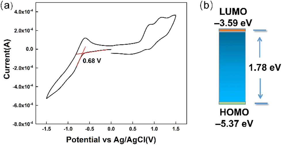 | ||
| Fig. 4 (a) Cyclic voltammetry diagram of TDIC; (b) energy level diagram. | ||
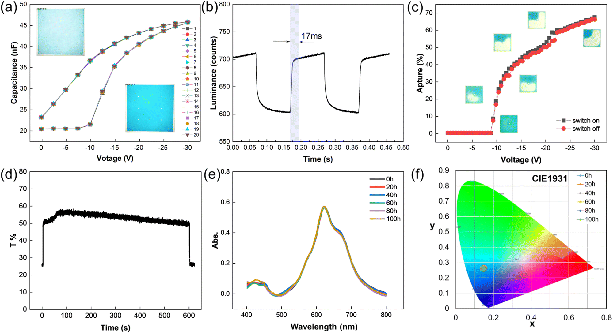 | ||
| Fig. 5 (a) 20 cycles capacitance curve of the EFD device with cyan oil; the inset showed the photo of the EFD devices; (b) the luminance of EFD device under voltage change between 0 V and −30 V; the response time is 17 ms; (c) the opening ratio of the EFD device with cyan oil; (d) the transmittance change of EFD device under −30 V within 10 min; (e) the optical stability of the EFD device with cyan oil; (f) the color change of the EFD device with increasing aging time. | ||
To verify the suitability of EFD devices with TDIC oil, EFD panels were fabricated, and the capacitance, response time, opening ratio, stability under an electric field and color change were all tested. By increasing the voltage, while the electric strength was larger than the capillary force, the oil layer broke; as a result, the capacitance increased dramatically, as shown in Fig. 5a. The EFD cell started to open at about −10 V, and the capacitance reached about 45 nF at −30 V for the EFD device tested with a display area 10 cm2. The capacitance dropped with decreasing voltage, the capillary force was dominant when below −10 V, and the oil spread over the fluoropolymer surface. The same consistency was maintained for 20 cycles of the C–V test, indicating that the EFD cell has no attenuation with cyan oil. As shown in Fig. 5b, the luminance of the EFD device under voltage change between 0 V and −30 V exhibited a fast response time of 17 ms. During switching, the opening ratio changed from 0% to 70% (Fig. 5c), resulting in the EFD panel switchover between cyan color and white color when the cyan oil layer spread and contracted. In addition, the cyan oil also showed electrochemical stability under voltage, and the switched-on pixels did not close back obviously within 10 minutes, as indicated in Fig. 5d, which means that the TDIC dye molecule cannot be protonated at the oil–water interface. The optical stability of the EFD cell with cyan oil was also examined; under the standard test conditions, the absorption of the cell and the CIE color both proved that the TDIC has excellent optical stability. The variation of the peak absorption after 100 h was less than 2% (Fig. 5e). In addition, the color coordinate (x = 0.15 ± 0.02, y = 0.26 ± 0.02) of TDIC before and after 100 h of the optical stability test (Fig. 5f) showed almost no change.
In the past, our team also reported the inkjet printing process for the fabrication of EFD devices.37 The most important parameter for inkjet oil was viscosity and surface tension. For TDIC oil, the viscosity was 1.05 mPa s for 10% (Fig. S10, ESI†), and the surface tension was 30 mN m−1, which was suitable for the inkjet printing process (Fig. 6). 149.6 × 71.2 mm2 and 400 × 500 mm2 EFD substrates were inkjet printed with TDIC oil, as shown in Fig. 6a and b. With inkjet printing, the volume of oil in each pixel can be strictly controlled, and the homogeneity of the oil layer as well as the optical performance were improved (Fig. 6c). The fabrication cost of EFD cells would be reduced, which would be conducive to the industrialization of the EFD display.
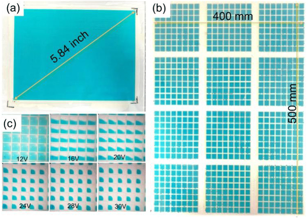 | ||
| Fig. 6 Inkjet printing of TDIC. (a) 5.84 inch; (b) 400 × 500 mm2 EFD devices; (c) opening pixels under different voltages. | ||
Conclusion
In conclusion, we designed and synthesized a terrylene diimide (TDI)-based cyan dye TDIC with an extraordinarily high molar absorption coefficient of up to 65000 L moL−1 cm−1, suitable LUMO energy level of −3.59 eV and color coordinate (x = 0.15 ± 0.02, y = 0.26 ± 0.02). Meanwhile, it exhibited superior device performance when used for the oil layer in the EFD with an opening voltage of about 10 V, a fast response time of 17 ms, and a high opening ratio of 70%. Moreover, TDIC exhibited high optical stability and the UV-vis absorption as well as the color coordinate almost showed no change for 100 h in the accelerated simulated sunlight aging test. Finally, the suitable viscosity and surface tension enables the realization of inject printing of EFD panels, indicating that TDIC may be a promising cyan oil for future commercial EFD application.
Experimental
Synthetic procedures
:100, V/V). Yield 55%. 1H NMR (600 MHz, CDCl3, TMS): δ = 8.378–8.364 (d, J = 8.4 HZ, 2H, CHaromat), 8.185–8.172 (d, J = 7.8 HZ, 2H, CHaromat), 4.071–4.059 (d, J = 7.2 HZ, 2H, N–CH2), 1.967–1.947 (m, 1H), 1. 320–1. 213 (m, 32H, 16 × CH2), 0.878–0.838 (m, 6H).
MS(MALDI-TOF): calculated for C74H94N2O4, 1074.7214; measured, 1074.7200.
13C-NMR (600 MHz, CDCl3, 27 °C, TMS): δ = 163.3, 154.7, 153.1, 146.8, 130.6, 129.1, 128.7, 128.9, 125.3, 122.7, 121.7, 121.6, 118.9, 57.2, 44.6, 38.4, 36.6, 32.4, 31.4, 31.8, 31.7, 30.0, 29.6, 29,3, 26.5, 22.7, 14.1.; MS (MALDI-TOF): calculated for C130H174N2O8, 1892.8280; measured 1892.3290.
Materials and methods
Materials
All chemicals were purchased from commercial sources and used without further purification unless otherwise specified. All solvents used were analytical grades from Merck or Sigma-Aldrich.Material characterization
UV-3300 spectrophotometer (MAPADA, Shanghai, China) was used to record the UV-vis absorption spectra of synthesized dyes. A PerkinElmer 841 spectrometer (PerkinElmer, Shelton, CT, USA) was used to record the FTIR spectra with KBr pellets. A Varian AS400 (Agilent, Santa Clara, CA, USA), Bruker AVANCE III 500 (Bruker BioSpin GmbH, Rheinstetten, Germany), and AVANCE NEO Bruker 600 (Bruker BioSpin GmbH) were used to record the 1H NMR and 13C NMR spectra in deuterated solvents using tetramethylsilane (TMS) as the internal standard. A Bruker Daltonics Microflex mass spectrometer (Bruker Daltonics, Bremen, Germany) was used to record the mass spectra. Electrochemical cyclic voltammetry (CV) was carried out on a CHI 660E Electrochemical Workstation. In the CV measurement, Pt disk as the working electrode, Pt wire as the counter electrode, and Ag/AgCl electrode as the reference electrode were used in a dried solution of methylene chloride with 0.1 M tetrabutylammonium hexafluorophosphate (NBu4PF6) at 100 mV s−1. Meanwhile, the CV of ferrocene was also taken for comparison.Molar absorption coefficient calculation
It was calculated by measuring the molar absorption coefficient (ε) for the longest wavelength of λmax with three different concentrations of cyan oil and their average value was obtained.Electrowetting curve
The electrowetting curve of DI water droplet on fluoropolymer-coated ITO electrode in cyan oil and pure decane was recorded by a contact angle measurement instrument under applied voltage in the range from 0 V to −40 V at a ramp rate of 1 V/1 s. A 2 × 2 cm2 ITO glass was coated with a dielectric layer (400 nm) and fluoropolymer (400 nm). Pt wire (0.1 mm) was used to connect the water droplet (1 μL) to the DC power source. During testing, the leakage current was monitored to make sure that the fluoropolymer layer was not broken.Oil formulation and viscosity measurement
Oil formulation: 0.5 g cyan dye was dissolved in 4.5 mL decane under sonication to form 10% cyan oil. The oil was filtered through a 0.2 μm syringe filter before use.For the inkjet printing of cyan oil, the viscosity of 5%, 10%, 15%, and 20% cyan oil was measured by an Anton Paar viscos-mitor (Lovis 2000 M). The interfacial tension of 10% was measured by the pendant drop technique with the Detaphysics Contact Angle System (OCA 15Pro) at 25°.
EFD device fabrication and test
The EFD device was fabricated according to the literature.38 Briefly, a 400 nm photoresist dielectric layer and a 400 nm Hyflon fluoropolymer hydrophobic layer were spin-coated on a clean ITO substrate, separately. The fluoropolymer layer was activated by RIE to coat the photoresist on top and make a pixel wall structure through the lithography process. The pixel size was μm × μm × 3.5 μm (height). The processed substrate was reflowed under 200 °C for 1 h. After the hydrophobic property of the recovered hydrophobic polymer, the cyan oil and the polar liquid (water) were filled into the pixels, and the display panel was sealed by a pressure-sensitive adhesive frame with a top ITO cover.EFD device electro-optical test
The EFD device was tested under applied voltage (−30 V) using a waveform generator (Agilent 33500B Series) with a square wave of 5 Hz frequency, and an Admesy colorimeter was used to record the response time.The opening ratio (OR = (1 – Aoil)/Apixel × 100%) was measured by a homemade setup that combined a microscope, a powder source, and a light source, the OR data was calculated through a program made by Visual Studio 2018.
The leakage current was detected by a pico-ammeter (Keithly 6487) during switching, and the capacitance change was recorded by a Wayne Kerr WK6500B.
The optical stability of the TDIC-filled panel was determined in a xenon arc lamp weather resistance test chamber (B-SUN-I). The simulation conditions were 0.55 W m−2 (340 nm) and a temperature of 45 °C for 100 h according to international standard IEC 60068-2-5: Procedure B. The degradation of the oil was monitored by measuring the absorbance curves every 20 h.
CIE color coordination measurement
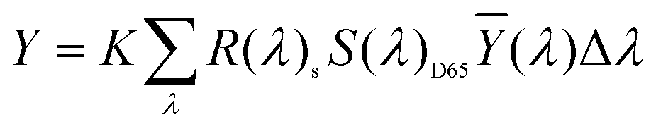
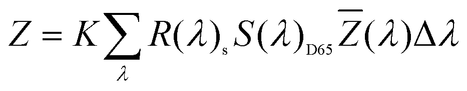
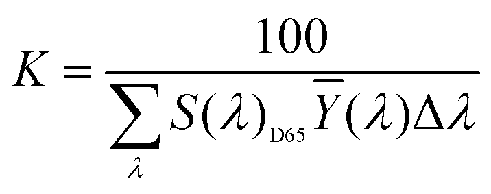
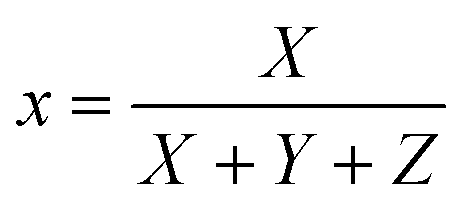
The sample was measured on a white reference background (Labsphere SRS-99-010 AS-01160-060) under a luminance meter (Topcon SR-UL1R) with the light source (OSRAM 46870 SP) on the upper lift of 45°. After the light source was adjusted to a reasonable color temperature (CCT), the spectral power of the white reference (P(λ)std) and the display (P(λ)s) was recorded. The reflection of the display can be calculated byand the CIE coordinates can then be calculated by the following equations.
Conflicts of interest
There are no conflicts of interest to declare.Acknowledgements
The present research is financially sponsored by the National Key R&D Program of China (2021YFB3600601), National Natural Science Foundation of China (No. 22008156), Science and Technology Program of Guangzhou (No. 2019050001, 202201010103), Program for Guangdong Innovative and Entrepreneurial Teams (No. 2019BT02C241), Program for Chang Jiang Scholars and Innovative Research Teams in Universities (No. IRT_17R40), Guangdong Provincial Key Laboratory of Optical Information Materials and Technology (No. 2017B030301007), Guangzhou Key Laboratory of Electronic Paper Displays Materials and Devices (201705030007), the Key Project of National Science Foundation of China (No. 12131010), MOE International Laboratory for Optical Information Technologies, the 111 projects.Notes and references
- M. Wang, Y. Guo, R. Hayes, D. Liu, D. Broer and G. Zhou, Forming spacers in situ by photolithography to mechanically stabilize electrofluidic-based switchable optical elements, Materials, 2016, 9, 250 CrossRef PubMed.
- N. R. Smith, L. Hou, J. Zhang and J. Heikenfeld, Fabrication and demonstration of electrowetting liquid lens arrays, J. Disp. Technol., 2009, 5, 411–413 Search PubMed.
- J. Heikenfeld, N. Smith, M. Dhindsa, K. Zhou, M. Kilaru, L. Hou, J. Zhang, E. Kreit and B. Raj, Recent progress in arrayed electrowetting optics, Opt. Photonics News, 2009, 4, 20–26 CrossRef.
- J. Heikenfeld, K. Zhou, E. Kreit, B. Raj, S. Yang, B. Sun, A. Milarcik, L. Clapp and R. Schwartz, Electrofluidic displays using Young-Laplace transposition of brilliant pigment dispersions, Nat. Photonics, 2009, 3, 292–296 CrossRef CAS.
- R. A. Hayes and B. J. Feenstra, Video-speed electronic paper based on electrowetting, Nature, 2003, 425, 383–385 CrossRef CAS PubMed.
- B. Tang, J. Groenewold, M. Zhou, R. A. Hayes and G. Zhou, Interfacial electrofluidics in confined systems, Sci. Rep., 2016, 6, 26593 CrossRef CAS PubMed.
- L. Shui, R. A. Hayes, M. Jin, X. Zhang, P. Bai, A. van den Berg and G. Zhou, Microfluidics for electronic paper-like displays, Lab Chip, 2014, 14, 2374–2384 RSC.
- M. Riahi, K. A. Brakke, E. Alizadeh and H. Shahroosvand, Fabrication and characterization of an electrowetting display based on the wetting–dewetting in a cubic structure, Optik, 2016, 127, 2703–2707 CrossRef CAS.
- R. Zhou, Q. Ye, H. Li, H. Jiang, B. Tang and G. Zhou, Experimental study on the reliability of water/fluoropolymer/ITO contact in electrowetting displays, Results Phys., 2019, 12, 1991–1998 CrossRef.
- B. Raj, M. Dhindsa, N. R. Smith, R. Laughlin and J. Heikenfeld, Ion and liquid dependent dielectric failure in electrowetting systems, Langmuir, 2009, 25, 12387–12392 CrossRef CAS PubMed.
- B. Burger and R. Rabot, Design of low hysteresis electrowetting systems in non-aqueous media by the addition of low HLB amphiphilic compounds, Colloids Surf., A, 2016, 510, 129–134 CrossRef CAS.
- K. Zhou, J. Heikenfeld, K. A. Dean, E. M. Howard and M. R. Johnson, A full description of a simple and scalable fabrication process for electrowetting displays, J. Micromech. Microeng., 2009, 19, 065029 CrossRef.
- T. Kato, S. Higuchi, Y. Fukushige, Y. Jimbo and D. Sasaki, Colored Composition for Electrowetting Display, Image Display Structure, and Electrowetting Display Device, US. Pat., 2014078572-A1, 2014 Search PubMed.
- M. M. H. Van De Weijer, R. Massard and R. A. Hayes, Electrowetting Elements, US. Pat., 8980141, 2011 Search PubMed.
- M. Ishida, Y. Shiga, U. Takeda and M. Kadowaki, Ink containing anthraquinone based dye, dye used in the ink, and display, US. Pat., 8999050, 2013 Search PubMed.
- Y. Deng, S. Li, D. Ye, H. Jiang, B. Tang and G. Zhou, Synthesis and a photo-stability study of organic dyes for electro-fluidic display, Micromachines, 2020, 11, 81 CrossRef PubMed.
- Y. Shiga, U. Takeda, S. Ichinosawa and M. Ishida, Ink containing heterocyclic azo dye, and dye for use in said ink. US. Pat., 8747537, 2014 Search PubMed.
- Y. Shiga and M. Ishida, Pyrazole disazo dye and ink containing the dye. US. Pat., 8143382, 2012 Search PubMed.
- Y. Chiang and Y. Chao, Synthesis of dis-azo black dyes for electrowetting displays, Mater. Sci. Eng. B, 2012, 177, 1672–1677 CrossRef CAS.
- L. D. Farrand, N. Smith, A. Corbett and A. Lawrence, Merck Patent GmbH. Electrowetting Fluids, US. Pat., 20150355456-A1, 2015 Search PubMed.
- Y. Chiang and Y. Chao, Synthesis and application of oil-soluble red dyes derived from p-n-Alkyl Aniline, Mater. Sci. Appl., 2014, 5, 485–490 CAS.
- S. Li, D. Ye, A. Henzen, Y. Deng and G. Zhou, Novel perylene-based organic dyes for electro-fluidic displays, New J. Chem., 2020, 44, 415–421 RSC.
- H. You and A. J. Steckl, Three-color electrowetting display device for electronic paper, Appl. Phys. Lett., 2010, 97, 023514 CrossRef.
- Y. Deng, H. Jiang., D. Ye, R. Zhou, H. Li, B. Tang, M. Jin, N. Li, Y. Guo and G. Zhou, Synthesis and application of an alkylated pyrazole-based azo dye for Electro-fluidic display, J. Soc. Inf. Disp., 2018, 26, 369–375 CrossRef CAS.
- Z. Liu, Y. Wu, Q. Zhang and X. Gao, Non-fullerene small molecule acceptors based on perylene diimides, J. Mater. Chem. A, 2016, 4, 17604–17622 RSC.
- W. Chen and Q. Zhang, Recent progress in non-fullerene small molecule acceptors in organic solar cells (OSCs), J. Mater. Chem. C, 2017, 5, 1275–1302 RSC.
- W. Chen, X. Yang, G. Long, X. Wan, Y. Chen and Q. Zhang, A perylene diimide (PDI)-based small molecule with tetrahedral configuration as a non-fullerene acceptor for organic solar cells, J. Mater. Chem. C, 2015, 3, 4698–4705 RSC.
- M. A. Niyas, R. Ramakrishnan, V. Vijay, E. Sebastian and M. Hariharan, Anomalous halogen-halogen interaction assists radial chromophoric assembly, J. Am. Chem. Soc., 2019, 141, 4536–4540 CrossRef CAS PubMed.
- D. Uersfeld, S. Stappert, C. Li and K. Müllen, Practical syntheses of terrylene chromophores from naphthalene and perylene building blocks, Adv. Synth. Catal., 2017, 359, 4184–4189 CrossRef CAS.
- F. Nolde, J. Qu, C. Kohl, N. G. Pschirer, E. Reuther and K. Müllen, Synthesis and modification of terrylenediimides as high-performance fluorescent dyes, Chem. – Eur. J., 2005, 11, 3959–3967 CrossRef CAS PubMed.
- C. L. Eversloh, Z. Liu, B. Müller, M. Stangl, C. Li and K. Müllen, Core-extended terrylene tetracarboxdiimide: synthesis and chiroptical characterization, Org. Lett., 2011, 13, 5528–5531 CrossRef PubMed.
- Y. Guo, Y. Deng, B. Xu, A. Henzen, R. Hayes, B. Tang and G. Zhou, Asymmetrical electrowetting on dielectrics induced by charge transfer through an Oil/Water interface, Langmuir, 2018, 34, 11943–11951 CrossRef CAS PubMed.
- S. Gan, L. Chen, Y. Feng, Y. Deng, R. Zhou, Y. Dou, B. Tang, L. Shui, Y. Wang, H. Li and G. Zhou, Protonation-induced molecular permeation at the oil/water interface in an electric field, Phys. Chem. Chem. Phys., 2018, 20, 29012–29017 RSC.
- Y. Guo, Y. Deng, B. Tang, A. Henzen and G. Zhou, The colored oil property effect on switching behavior of electro-fluidic display, Mater. Sci. Appl., 2020, 11, 167–176 CAS.
- J. Pommerehne, H. Vestweber, W. Guss, R. F. Mahrt, H. Bassler, M. Porsch and J. Daub, Adv. Mater., 1995, 7, 551 CrossRef CAS.
- W. Chen, J. Zhang, G. Long, Y. Liu and Q. Zhang, From non-detectable to decent: replacement of oxygen with sulfur in naphthalene diimide boosts electron transport in organic thin-film transistors (OTFT), J. Mater. Chem. C, 2015, 3, 8219–8224 RSC.
- Y. Guo, J. Yan, Z. Shen, H. Jiang, B. Tang, Y. Deng, A. Henzen, R. Zhou and G. Zhou, Electrofluidic displays based on inkjet printing and phase change filling, J. Micromech. Microeng., 2020, 30, 105001 CrossRef CAS.
- Y. Guo, L. Zhuang, H. Feng, B. Zhong, A. Henzen, J. Groenewold, F. Liu, Y. Deng, B. Tang and G. Zhou, Programmable control of two-phase fluid interface relative motion in electrowetting device, Adv. Mater. Interfaces, 2021, 8, 2101086–2101095 CrossRef CAS.
Footnotes |
| † Electronic supplementary information (ESI) available. See DOI: https://doi.org/10.1039/d3ma00177f |
| ‡ Yong Deng and Yuanyuan Guo contributed equally to this article. |
| This journal is © The Royal Society of Chemistry 2023 |