 Open Access Article
Tailoring intra-molecular coupling in BDT-based copolymers to enhance their performance in fullerene-free organic solar cells†
Newayemedhin A.
Tegegne
 *ab,
Asfaw
Negash
*c,
Desalegn
Yilma
d,
Kidan G.
Gebremariam
a,
Zewdneh
Genene
e,
Wendimagegn
Mammo
d and
Neill J.
Goosen
b
aDepartment of Physics, Addis Ababa University, P.O. Box 1176, Addis Ababa, Ethiopia. E-mail: newaye.medhin@aau.edu.et
bDepartment of Chemical Engineering, Stellenbosch University, Stellenbosch 7604, South Africa
cDepartment of Chemistry, Debre Berhan University, P.O. Box 405, Debre Berhan, Ethiopia. E-mail: asfawnegash@dbu.edu.et
dDepartment of Chemistry, Addis Ababa University, P.O. Box 33658, Addis Ababa, Ethiopia
eDepartment of Chemistry and Chemical Engineering, Chalmers University of Technology, SE412 96, Gothenburg, Sweden
First published on 8th November 2023
Abstract
Three copolymers based on a 4,8-bis(4,5-dioctylthiophen-2-yl)benzo[1,2-b:4,5-b′]dithiophene (BDTT) donor unit coupled with 6-(2-ethylhexyl)-5H-[1,2,5]thiadiazolo[3,4-f]isoindole-5,7(6H)-dione (P1), 6-octyl-4,8-di(thiophen-2-yl)-5H-[1,2,5]thiadiazolo[3,4-f]isoindole-5,7(6H)-dione (P2) and 2-(2-ethylhexyl)-6-octyl-4,8-di(thiophen-2-yl)-[1,2,3]triazolo[4,5-f]isoindole-5,7(2H,6H)-dione (P3) acceptors were computationally designed and experimentally synthesized to tailor the intramolecular coupling in their backbone. A considerable decrease in distortion energy in P2 compared to P1 proved the major role of the π-spacer in the copolymer in releasing steric strain. In comparison to the [1,2,3]triazolo[4,5-f]isoindole-5,7(2H,6H)-dione-based copolymer, P3, the lower electrostatic potential (ESP) of the [1,2,5]thiadiazolo[3,4-f]isoindole-5,7(6H)-dione acceptor in P1 has been observed to shift its LUMO energy level by about 0.5 eV. Furthermore, the electron donating properties of the copolymers increased in the order of P1 < P2 < P3 due to the synergistic contribution of each unit rather than a single unit, confirming the importance of tailoring the intramolecular coupling to control the electro-optical properties of the copolymers. Finally, the copolymer with a poorer electron acceptor unit (P3) was found to exhibit complementary absorption with the non-fullerene acceptor, ITIC, yielding a PCE of 8.87% in solar cell devices, further demonstrating the relevance of each unit in the copolymer intramolecular coupling.
1 Introduction
Organic solar cells (OSCs) have been the subject of intensive research for the past three decades, with the results in the last decade paying off the great effort of the researchers, with PCEs reaching 19% in both single and multi-junction devices.1–7 Structural engineering of a vast variety of novel donor co-polymers using the donor–acceptor (D–A) strategy and the emergence of small molecule acceptors such as Y6 have played a critical role in this accomplishment.The optical, electrical, and morphological properties of conjugated polymers can be effectively tailored using rationally designed D–A coupling. isoindigo,8,9 quinoxaline,10 benzothiadiazole (BTD)11 and benzotriazole (BTA) are a few examples of acceptor materials that are frequently utilized as electron withdrawing units in D–A copolymers. Due to its lower electron withdrawing properties compared to the BTD acceptor, the BTA unit is frequently utilized in the design of wide band gap co-polymers. By further lowering their HOMO level and the ensuing rise in open circuit voltage (Voc), BTA units were successfully incorporated into copolymers to achieve efficiencies over 10% in OSC devices.12 By introducing a cyclic-imide onto the BTA moiety, the polymer's LUMO and HOMO energy levels could be efficiently reduced resulting in high Voc. Lan et al.13 reported the synthesis of a D–A type polymer (PTZBIBDT) using 2,6-dioctyl-4,8-di(thiophen-2-yl)-[1,2,3]triazolo[4,5-f]isoindole-5,7(2H,6H)-dione as an acceptor unit and OSCs based on a PTZBIBDT:PC71BM (phenyl-C 71-butyric acid methyl ester) blend achieved a PCE of 8.63%. Following this report, a number of copolymers utilizing 2,6-dioctyl-4,8-di(thiophen-2-yl)-[1,2,3]triazolo[4,5-f]isoindole-5,7(2H,6H)-dione,14,15 and 6-octyl-4,8-di(thiophen-2-yl)-5H-[1,2,5]thiadiazolo[3,4-f]isoindole-5,7(6H)-dione16 have been reported for OSC application mainly due to their matching energy-levels and the possibility of alkylation at the cyclic imide group, which is beneficial for improving the active layer morphology.
Electron donor units such as benzodithiophene (BDT) have been employed in high performing polymers due to their planar structure and good charge carrier mobility. However, the electron donating nature of BDT is lowered by the sulfur atom in its backbone. Substitutions such as alkylthiothenyl, alkylphenyl17 methylthio18 and thiophene (Th) of BDT have shown improved electron donating properties hence resulting in a better PCE in OSCs.19,20 In addition to the electron donating and accepting units, the π-spacer also plays a considerable role in modifying the backbone structure by releasing the steric strain consequently improving their molecular conformation.21,22 On the other hand, the bridges can also tailor the D–A coupling in the copolymer which determines their electro-optical properties.
In this contribution, three copolymers with a BDTT donor unit, namely poly[4,8-bis(4,5-dioctylthiophen-2-yl)benzo[1,2-b:4,5-b′]dithiophene-alt-6-(2-ethylhexyl)-5H-[1,2,5]-thiadiazolo[3,4-f]isoindole-5,7(2H,6H)-dione] (P1), poly[4,8-bis(4,5-dioctylthiophen-2-yl)benzo[1,2-b:4,5-b′]dithiophene-alt-6-octyl-4,8-di(thiophen-2-yl)-5H-[1,2,5]thiadiazolo-[3,4-f]isoindole-5,7(2H,6H)-dione] (P2) and poly[4,8-bis(4,5-dioctylthiophen-2-yl)benzo[1,2-b:4,5-b′]dithiophene-alt-2-(2-ethylhexyl)-6-octyl-4,8-di(thiophen-2-yl)-[1,2,3]triazolo[4,5-f]isoindole-5,7(2H,6H)-dione] (P3), were designed computationally and synthesized to effectively tune the intramolecular coupling to improve their performance in non-fullerene-based OSCs. The optical, electrical and electrochemical properties of the three copolymers differ significantly. The intramolecular interaction in the copolymers was found to be the primary cause of the observed considerable differences, as confirmed computationally. Finally, the photovoltaic performances of the polymers were investigated using 3,9-bis(2-methylene-(3-(1,1-dicyanomethylene)-indanone))-5,5,11,11-tetrakis(4-hexylphenyl)-dithieno[2,3-d:2,3-d]-s-indaceno[1,2-b:5,6-b]dithiophene (ITIC) as an acceptor and a power conversion efficiency (PCE) of 3.53% was recorded for the P1:ITIC-based device, which was improved to 7.02% for the P2:ITIC-based device. The best solar cell performance was recorded for the P3:ITIC-based device, which exhibited a PCE of 8.87% mainly owing to the significant increase in short circuit current (Jsc), due to its complimentary absorption with ITIC.
2 Experimental section
2.1 Synthesis of co-polymers P1, P2 and P3
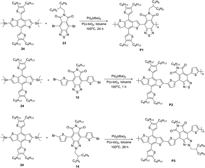
Most starting materials and reagents were purchased from Sigma-Aldrich and were used as received. 2,6-Bis(trimethyltin)-4,8-bis(4,5-dioctylthiophen-2-yl)benzo[1,2-b;4,5-b]dithiophene (24) was purchased from Solarmer Materials Inc. China, and was directly used to prepare polymers. The syntheses of monomers 9, 19 and 23 are depicted in Schemes S1–S3 of the ESI.† The NMR spectra of 9, 19 and 23 are shown in Fig. S1–S8 (ESI†). P1, P2 and P3 were prepared from the corresponding monomers using the Stille polymerization reaction as shown in Scheme 1.2.2 Electro-chemical study
A BASi Epsilon-EC potentiostat was used to record the square wave voltammetry traces of the copolymers. A three-electrode arrangement was used, consisting of an Ag/Ag+ quasi reference electrode, a platinum wire counter electrode, and a platinum disk working electrode. The supporting electrolyte was a 0.1 M solution of tetrabutylammoniumperchlorate (TBAP) in anhydrous acetonitrile. From a chloroform solution, a thin polymer film was cast onto the working electrode. Prior to the experiment, nitrogen was bubbled into the electrolyte solution. Nitrogen was flushed over the electrolyte surface throughout the scans. After using 0.5 and 0.3 µm Al2O3 slurry to polish the platinum disk, it was extensively rinsed with de-ionized water and acetonitrile. By measuring the ferric/ferrous (Fe(III)/Fe(II)) redox couple in the supporting electrolyte–solvent system, the potential of the quasi-reference electrode was corrected to the Ag/AgCl reference electrode, which was determined to be 0.1 V versus Ag/AgCl. All potentials were measured in volts in relation to an Ag/AgCl reference electrode. The HOMO energy levels were calculated using the formula given in eqn (1) from their respective ionization potentials estimated from the onset of oxidation (Eoxonset), whereas the LUMO level was calculated by subtracting the HOMO energy from their optical band gap.| EHOMO/LUMO = −(Eoxonset + 4.4) eV | (1) |
2.3 Absorption
The absorption spectra of the copolymers in solution and as thin films as well as the copolymer–ITIC blends thin films were measured with a PerkinElmer Lambda 19 UV-vis spectrophotometer. To prepare thin films, the copolymers and their blends with ITIC were dissolved in 1,2-dichlorobenzene (o-DCB) to form solutions with a concentration of 25 mg mL−1 and heated at 80 °C for 4 h. The thin films were then obtained by spin coating the o-DCB solutions on glass substrates and annealing at 130 °C for 10 min to remove the solvent.2.4 OSC device fabrication and characterization
The photovoltaic (PV) performances of the copolymers were evaluated using OSCs in a device geometry of ITO (indium tin oxide)/PEDOT:PSS(poly(3,4-ethylenedioxythiophene))–poly(styrenesulfonate)/copolymer:ITIC/poly[(9,9-bis(3′-(N,N-dimethylamino)propyl)-2,7-fluorene)-alt-2,7-(9,9-dioctylfluorene)] (PFN)/Al (aluminum). The commercially obtained ITO glass substrate was coated with PEDOT:PSS obtained from Heraeus Clevios at 3500 rpm for 40 s to obtain a 40 nm thick hole transport layer. The active layer solution was prepared by mixing the copolymers with ITIC at a 1![[thin space (1/6-em)]](https://www.rsc.org/images/entities/char_2009.gif) :
:![[thin space (1/6-em)]](https://www.rsc.org/images/entities/char_2009.gif) 1 ratio with and without 1% v/v 1-chloronaphthalene (1-CN). Following the active layer deposition, an electron transport layer, PFN, was spin coated. Finally, the Al electrode was thermally evaporated at ≈3 × 10⁶ mbar to cap the device. The active layer area was carefully determined using an optical microscope to 4 mm2 and the active layer thickness was measured using a Dektak profilometer. The PV performances of the devices were determined from their current–voltage characteristics recorded using a Keithley-2400 source meter at an illumination intensity of 100 mW cm−2 from a solar simulator MODEL SS-50AAA.
1 ratio with and without 1% v/v 1-chloronaphthalene (1-CN). Following the active layer deposition, an electron transport layer, PFN, was spin coated. Finally, the Al electrode was thermally evaporated at ≈3 × 10⁶ mbar to cap the device. The active layer area was carefully determined using an optical microscope to 4 mm2 and the active layer thickness was measured using a Dektak profilometer. The PV performances of the devices were determined from their current–voltage characteristics recorded using a Keithley-2400 source meter at an illumination intensity of 100 mW cm−2 from a solar simulator MODEL SS-50AAA.
2.5 Computational study
Density functional theory (DFT) calculations were performed using a Gaussian 16 package to complement the experimental studies. The structural input files were created and the results were viewed using GaussView 3.0. Different levels of theories including M06, B3LYP, and CAM-B3LYP with a 6-31G(d,p) basis set were used in DFT and time-dependent DFT (TD-DFT) calculations. The results obtained were analyzed using Avogadro and Multiwfn 3.7 software.233 Results and discussion
3.1 Geometry optimization
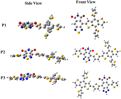
The backbone geometries of P1, P2, and P3 were optimized by first performing vibrational analysis on the energetically lowest structures with no negative vibrational modes.The steric hindrance between the D, π-spacer, and A moieties in each copolymer can be investigated by comparing the torsion angle in the copolymer's backbone, which can be quantified by comparing the energy cost to planarize the molecule from its optimized geometry, also known as distortion energy (ΔEdis). In this regard, the ΔEdis of the copolymers were computed by setting the dihedral angles of the optimized single units to zero and computing the single point energies on the restricted geometries. The ΔEdis is then calculated as the energy difference between the optimized and constrained geometry. The computed ΔEdis energy of P1 (6.77 eV) was reduced to 1.67 eV in P2 owing to the thiophene π-spacer that releases the steric strain in the backbone. The ΔEdis is further reduced to 1.22 eV in P3, confirming the significant improvement in the backbone conformation in the D–π–A copolymers. Several researchers have stressed the need for planarizing the backbones of polymers in order to considerably improve their electro-optical properties.24–26 More planar conformations in D–π–A copolymers are expected to significantly improve the charge mobility in their backbone, hence increasing the Jsc of the OSCs. Fig. 1 depicts the front and side views of the optimized geometries of P1, P2 and P3 to provide a visual representation of the calculated ΔEdis.
3.2 Optical properties
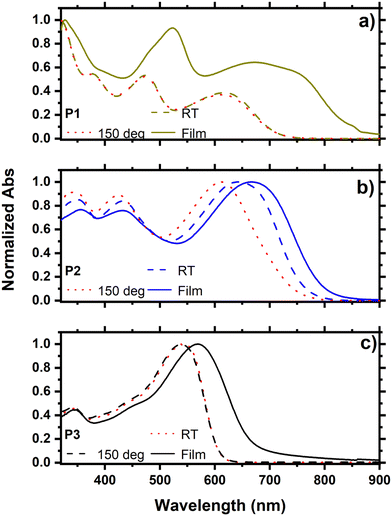
The UV-vis absorption spectra of P1, P2, and P3 were recorded both in solution and as thin films (Fig. 2). Owing to the π−π* transition at their backbone and intramolecular charge transfer (ICT) between the donor and acceptor units, the three copolymers revealed a common two-band absorption characteristics.27,28 The absorption spectra of P1 and P3 recorded in solution at RT and 150 °C showed no change, while a significantly blue-shifted spectrum was observed for P2 at 150 °C. This result suggests that P2 forms aggregates at RT even in dilute solution, and that increasing the temperature will disaggregate the chains resulting in a blue shift in the absorption spectrum. The introduction of a thiophene π-spacer in the backbone of P2 compared to P1 is responsible for this effect, which confirms the considerable conformation change in going from P1 to P2. This is also consistent with the considerable reduction in ΔEdis in P2 compared to P1 caused by the π-spacer relaxing the steric stress in the D–π–A copolymer P2. The absorption spectra of thin films of P1, P2 and P3 are red-shifted compared to the corresponding spectra in solution demonstrating strong π−π* stacking in the solid state. However, the extent of the shift is substantially smaller in P2, owing to the existence of aggregates in dilute solution, as evidenced by its blue-shifted absorption in a hot solution at 150 °C. The optical band gaps of the copolymers were determined from their absorption onsets in the thin-film spectra and were found to be 1.56, 1.60, and 1.83 eV, for P1, P2, and P3, respectively (Table 1).| Name | M n (kDa) | M W (kDa) | λ maxsoln (nm) | λ maxFilm (nm) | λ onset (nm) | E optg (eV) | HOMOa (eV) | LUMOa (eV) | HOMOb (eV) | LUMOb (eV) |
|---|---|---|---|---|---|---|---|---|---|---|
| a Experimental values. b Calculated for the trimers. | ||||||||||
| P1 | 56.9 | 180.0 | 613 | 669 | 861 | 1.56 | −5.62 | −4.06 | −5.32 | −2.81 |
| P2 | 53.4 | 200.7 | 659 | 667 | 803 | 1.60 | −5.58 | −3.98 | −5.25 | −2.82 |
| P3 | 31.8 | 232.7 | 536 | 572 | 678 | 1.83 | −5.56 | −3.73 | −5.18 | −2.26 |
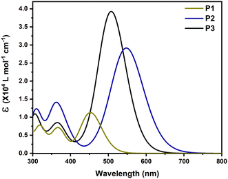
To investigate the relationship between the structure and optical characteristics, the absorption spectra of the copolymers were simulated in trimers using TD-DFT at the B3LYP-CAM level of theory in chlorobenzene. The spectra were generated by convolution of Gaussian functions with a FWHM of 0.4 eV centered at the excitation wavelengths, as shown in Fig. 3. Table 2 summarizes the significant results, which include the transition energy of the first excited state, its oscillator strength, and the contribution of molecular orbitals. Due to the limited number of units included in the calculation (3 units) compared to the many-units in the actual copolymers, the absorbances of the trimers computed using TD-DFT are blue-shifted compared to the experimental findings. When the absorption of P2 is compared to that of P1, it can be seen that its S0 → S1 transition is red-shifted with a higher oscillator strength, owing to the thiophene π-spacer. The absorption maximum of the benzotriazole-based copolymer (P3) is at 509.07 nm, which is blue-shifted compared to P2 owing to the weaker benzotriazole-based electron withdrawing unit. The oscillator strength of the S0 → S1 transition, on the other hand, is highest in P3.
| Polymer | Transition | Energy (eV) | λ st (nm) | f | Main MO contribution |
|---|---|---|---|---|---|
| P1 | S0 → S1 | 2.73 | 453.67 | 1.61 | H → L (56.5%), H−1 → L+1 (11.9%) |
| P2 | S0 → S1 | 2.25 | 550.14 | 4.12 | H → L (50.4%), H−1 → L+1 (14.4%) |
| P3 | S0 → S1 | 2.44 | 509.07 | 5.65 | H → L (52.7%), H−1 → L+1 (15.9%) |
3.3 Electro-chemical properties
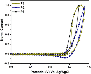
The electrochemical characteristics of P1, P2, and P3 were studied using cyclic voltammetry (CV), as illustrated in Fig. 4. The HOMO energy levels of P1, P2, and P3 were calculated from the onsets of their oxidation using eqn (1) and were found to be −5.62, −5.58, and −5.56 eV, respectively. The LUMO energy levels of P1, P2, and P3, calculated by subtracting the HOMO energy levels from the optical gaps (Eoptg), were found to be −4.06, −3.98 and −3.73 eV, respectively. The LUMO energy level of P3 was found to be higher than those of P1 and P2 due to the weaker acceptor strength of the 2H-benzo[d][1,2,3]triazole moiety in P3 compared to the benzo[c][1,2,5]thiadiazole moiety in P1 and P2.29DFT calculations were performed for the trimers at the B3LYP level of theory using the 6-31G(d,p) basis set to elucidate the differences in the FMOs of P1, P2 and P3, and the results are presented in Table 1. The calculated values for the FMO energy levels mirror the pattern of the experimental findings. However, because fewer units were taken into account in the DFT calculations, the values are anticipated to differ from the experimental results. Intriguingly, the LUMO levels of P1 and P2 are nearly identical, indicating that the π-spacer has a negligible effect on the energy level. In contrast, switching the acceptor from benzothidiazole-based to benzotriazole-based, the LUMO level increased by more than 0.5 eV, owing to the weaker electron withdrawing properties of the latter. The HOMO level, on the other hand, was determined by the contribution of each unit, as shown in Table 1. This could be because the donor's ability to donate electrons altered as the structures of the co-polymers changed.
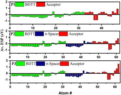
Since the energy levels of the copolymers are dictated by the electronic distribution in the backbones, the ESP at each atom of the single units of the copolymers was computed in order to better understand the cause of the difference in the FMOs of the copolymers,30 as shown in Fig. 5. The ESPs of the BDTT and π-spacer units are generally negative, confirming their electron donating properties, whereas a negative ESP value was found for the acceptor units of all three copolymers. Interestingly, the ESP values of BDTT were found to be decreasing in the order of P1 (−5.15 eV) < P2 (−6.07 eV) < P3 (−7.14 eV), indicating an increasing order of electron donating properties in the copolymer. Consequently, the HOMO levels are expected to shift upward in the order of P1 < P2 < P3,30,31 as shown in Table 1. It is worth noting that the same electron donating BDTT unit has different ESP values in the copolymers clearly confirming the synergistic contribution of the coupling between electron donating and accepting units that determine the HOMO level. This highlights the importance of intramolecular coupling in determining the electrochemical properties of the polymers. However, the ESP values of the acceptors in the D–π–A copolymers were found to be higher in P2 (1.71 eV) than in P3 (1.40 eV), confirming the lower electron withdrawing properties of the benzotriazole unit in P3 due to the lone electron pairs on the nitrogen atom at the 2-position, resulting in an up-shifted LUMO level.
DFT was used to further evaluate the molecular orbital distribution, as shown in Fig. S9 (ESI†). While the LUMOs of P2 and P3 are largely localized on their acceptor units, their HOMOs are highly delocalized along the polymer backbones. In contrast, the LUMO of P1 is localized on the acceptor while its HOMO is localized on the BDT unit. The orbital delocalization index (ODI) of the copolymers was computed using the Hirshfeld method to determine the difference in their FMO localization.32 ODI can be used to directly quantify the extent of orbital spatial delocalization throughout the backbone of a copolymer. The smaller the ODI, the more confined the orbital is inside a few atoms. The corresponding HOMO (LUMO) delocalization indexes of the P1, P2 and P3 were determined to be 6.12 (9.31), 4.47 (8.18), and 4.22 (4.94), respectively. This further supports the finding that P3 has a lower spatial charge separation due to its poor ICT properties as a result of the lower electron withdrawing characteristic of the 2H-benzo[d][1,2,3]triazole moiety in P3 compared to the benzo[c][1,2,5]thiadiazole acceptor in P1 and P2.33
3.4 Density of states (DOS)
The intramolecular coupling in copolymers is determined by the interaction between donor and acceptor moieties. In this regard, the contribution of each moiety to the FMOs can be used to highlight the importance of each unit. The total (TDOS) and partial density of states (PDOS) of the P1, P2 and P3 were calculated by fragmenting the copolymers into each donor, acceptor and π-spacer moiety as given in Fig. 6. The contribution of BDT to the HOMO of P1, P2 and P3 was found to be 94.89, 76.82 and 71.19%, respectively, clearly showing the more localized nature of the HOMO in the donor unit of P1 compared to P2 and P3. On the other hand, the benzo[c][1,2,5]thiadiazole acceptor moiety in P1 and P2 has 87.05 and 80.14% contribution, respectively, to their LUMOs while the contribution of the 2H-benzo[d][1,2,3]triazole unit to the LUMO of P3 was reduced to 59.40% further confirming the poor electron withdrawing properties of the benzotriazole moiety. Hence, poor intramolecular coupling in P3 will result in a blue-shifted absorption.30 On the other hand, the thiophene-spacer in P2 was found to have a significant contribution, both to the HOMO (17.18%) and LUMO (16.25%), further pushing the FMO energy levels to lower its band gap.21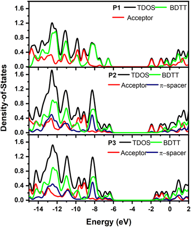 | ||
| Fig. 6 PDOS of BDT (green), π-spacer (blue), acceptor (navy) and total DOS (black) calculated for single units of P1, P2 and P3 single units. | ||
3.5 Exciton binding energy
When a polymer is mixed with an acceptor in the active layer of an OSC, the exciton binding energy (Eb) of the polymer influences the exciton dissociation efficiency. In this regard, the difference between the electrochemical (EECgap = LUMO − HOMO) and optical (Eoptg) band gaps (eqn (2)) was used to calculate the Eb of the three copolymers.34,35| Eb = EECgap − Eoptg. | (2) |
The Eb in P1, P2, and P3 was determined to be 0.70, 0.35, and 0.22 eV, respectively. The high exciton binding energy of P1 is expected to inhibit exciton dissociation, resulting in a lower Jsc in OSC devices.
3.6 Photovoltaic performance
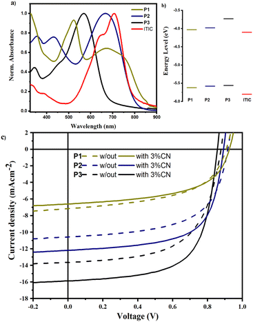
The photovoltaic performances of the copolymers were examined utilizing ITIC as an acceptor in a device architecture of Glass/ITO/PEDOT:PSS/active-layer/PFN/Al. Fig. 7 depicts the J–V curves of the manufactured devices, as well as the absorbance and energy levels of the copolymers and ITIC, and Table 3 summarizes the corresponding PV parameters. The PCEs of P1:ITIC, P2:ITIC, and P3:ITIC based OSCs without (with) 1-CN additive were found to be 3.25% (3.53%), 5.53% (7.02%), and 7.08% (8.87%), respectively. The PCE of the P2-based devices showed a nearly two-fold increase compared to P1-based devices largely due to enhanced Jsc and FF as shown in Table 3. The enhanced Jsc agrees with the increased planarity (substantially lower backbone torsion angle) as well as the decreased exciton binding energy in P2 compared to P1.6,36 Furthermore, the absorption of P2 was greater than P1 above 500 nm, where the solar radiation flux is higher, enhancing charge generation in P2:ITIC-based devices (see Fig. 7a). In P3-based devices, the Jsc increased to 15.68 mA cm−2, owing to the blue-shifted absorption compared to P2, which is complementary to the absorption of ITIC, as shown in Fig. 7a. As a result, the optimized P3:ITIC-based devices achieved the highest PCE of 8.87%. It is widely known that the molecular structure of the active layer materials and the active layer morphology of OSCs are closely connected. According to reports, planar molecules provide an excellent morphology that promotes free charge formation, exciton dissociation, and diffusion.36,37 Therefore, the more planar structures of P2 and P3 promote enhanced active layer morphology, resulting in higher FFs, probably by preventing the local aggregation of ITIC molecules in the coiled copolymer chain.30| Active layer | Additive ratio | V oc (V) | J sc (mA cm−2) | FF (—) | PCEMax (Av) (%) |
|---|---|---|---|---|---|
| (Av) Average calculated for more than 10 devices. | |||||
P1![[thin space (1/6-em)]](https://www.rsc.org/images/entities/char_2009.gif) : :![[thin space (1/6-em)]](https://www.rsc.org/images/entities/char_2009.gif) ITIC (1 ITIC (1![[thin space (1/6-em)]](https://www.rsc.org/images/entities/char_2009.gif) : :![[thin space (1/6-em)]](https://www.rsc.org/images/entities/char_2009.gif) 1) 1) |
No | 0.96 | 6.61 | 0.53 | 3.25 (3.25 ± 0.08) |
| 1% CN | 0.91 | 7.18 | 0.54 | 3.53 (3.44 ± 0.09) | |
P2![[thin space (1/6-em)]](https://www.rsc.org/images/entities/char_2009.gif) : :![[thin space (1/6-em)]](https://www.rsc.org/images/entities/char_2009.gif) ITIC (1 ITIC (1![[thin space (1/6-em)]](https://www.rsc.org/images/entities/char_2009.gif) : :![[thin space (1/6-em)]](https://www.rsc.org/images/entities/char_2009.gif) 1) 1) |
No | 0.92 | 10.60 | 0.58 | 5.53 (5.47 ± 0.06) |
| 1% CN | 0.90 | 12.24 | 0.64 | 7.05 (6.98 ± 0.07) | |
P3![[thin space (1/6-em)]](https://www.rsc.org/images/entities/char_2009.gif) : :![[thin space (1/6-em)]](https://www.rsc.org/images/entities/char_2009.gif) ITIC (1 ITIC (1![[thin space (1/6-em)]](https://www.rsc.org/images/entities/char_2009.gif) : :![[thin space (1/6-em)]](https://www.rsc.org/images/entities/char_2009.gif) 1) 1) |
No | 0.88 | 13.62 | 0.59 | 7.07 (7.02 ± 0.05) |
| 1% CN | 0.86 | 15.68 | 0.65 | 8.87 (8.87 ± 0.09) | |
On the other hand, the Voc of the P1-based devices was found to be higher than P2- and P3-based devices, mainly due to the low-lying HOMO level, as a result of the strong coupling between the donor and acceptor. In P2 and P3, the thiophene-spacer causes the HOMO level to shift upward thereby reducing the Voc values of the devices. It is worth noting that the Voc values of the devices fabricated by using 1-CN as an additive are consistently lower than those of the devices prepared without an additive probably due to the reduced energy difference between the excited polymers and the charge transfer state of the polymer:ITIC blend.38
3.7 Charge mobility
Electron-only and hole-only devices, made using the diode architecture of ITO/ZnO/active layer/PFN/Al and ITO/PEDOT:PSS/active layer/Au, respectively, were used to measure the electron and hole mobility mobilities of the devices. The Mott–Gurney model was used to fit the space charge limited current (SCLC) region of the dark – J–V characteristics of the devices as depicted in Fig. S10 (ESI†), in order to determine the field-dependent mobility (µ) as stated in eqn (3).39 | (3) |
The electron and hole mobilities in the copolymers increased as the steric hindrance in their backbone diminished, resulting in an increase in the Jsc. Furthermore, the lower FF of P1-based devices is due to higher charge recombination as a result of unbalanced charge transport. The FF of P2- and P3-based devices, on the other hand, increased when treated with 1-CN to 64 and 65%, respectively, due to better balanced charge transport  , as shown in Table 4. Additionally, the devices fabricated using D–π–A copolymers were found to have smooth surfaces with RMS values of 1.06 and 0.65 nm without the processing additive and 0.72 and 0.42 nm after using 3% CN additive in P2 and P3 based devices. Fig. S11 (ESI†) illustrates this better topography in the devices due to their improved backbone geometry.
| Active layer (—) | Additive (—) | µ e × 10−4 cm2 V−1 s−1 | µ h × 10−4 cm2 V−1 s−1 | µ e/µh (—) |
|---|---|---|---|---|
| P1:ITIC | No | 0.58 | 1.02 | 1.75 |
| 1% CN | 0.66 | 0.79 | 0.58 | |
| P2:ITIC | No | 1.95 | 2.22 | 1.12 |
| 1% CN | 2.10 | 2.20 | 1.05 | |
| P3:ITIC | No | 2.36 | 2.48 | 1.05 |
| 1% CN | 2.31 | 2.40 | 1.04 |
4 Conclusion
Three D–A copolymers P1, P2 and P3 were computationally designed and successfully synthesized. P1 and P2 are based on a BDTT donor and 5H-[1,2,5]thiadiazolo[3,4-f]isoindole-5,7(6H)-dione acceptor. P2 is different from P1 in which it contains thiophene as a π-spacer between the donor and acceptor units. On the other hand, P3 contains a BDTT as a donor, [1,2,3]triazolo[4,5-f]isoindole-5,7(2H,6H)-dione as an acceptor and thiophene as a π-spacer. The backbone conformations and electro-optical properties of the copolymers differ greatly, highlighting the role of each unit in fine-tuning their properties. The thiophene spacer was shown to considerably reduce torsional strain in P2 and P3, resulting in a 4-fold drop in distortion energy in their backbone compared to P1. The contribution of each unit to the FMOs was determined by their PDOS, and the results confirmed that the contribution of BDTT to the HOMO of the donors was significantly reduced in the D–π–A copolymers P2 and P3 compared to the D–A copolymer, P1, confirming the importance of the π-spacer in diluting the ICT properties in the backbone. Compared to P1 and P2, the LUMO of P3 was found to be up-shifted by more than 0.5 eV due to its lower ESP, resulting in a blue-shifted absorption. The PV performances of P1, P2 and P3 were studied with ITIC as an acceptor and with and without 1-CN as a processing additive. The PCEs of the best-performing devices were found to be 3.53, 7.02, and 8.87% for P1, P2 and P3, respectively. The highest PCE was recorded for P3-based devices because of the complementary absorption of P3 with ITIC, reduced exciton binding energy, and planar geometry, which resulted in higher electron and hole mobilities.Author contributions
NT AN, and KG contributed to the experimental and computational work and first draft writing, and ZG, DY and WM synthesized the polymers. All authors contributed equally to data curing, analysis and interpretation, and final manuscript editing.Data availability
The data reported in this work are available from the corresponding authors upon reasonable request.Conflicts of interest
The authors assert that there is no known conflict of interest to declare.Acknowledgements
This work is supported by the Carnegie foundation of New York through African Research Universities Alliance (ARUA). WM, ZG and DY acknowledge the International Science Program (ISP) of Uppsala University, Sweden, for financial support.References
- R. Sun, Y. Wu, X. Yang, Y. Gao, Z. Chen, K. Li, J. Qiao, T. Wang, J. Guo, C. Liu, X. Hao, H. Zhu and J. Min, Adv. Mater., 2022, 34, 2110147 CrossRef CAS PubMed.
- M. Liu, X. Ge, X. Jiang, F. Guo, S. Gao, Q. Peng, L. Zhao and Y. Zhang, Adv. Funct. Mater., 2023, 2300214 CrossRef CAS.
- Z. Zheng, J. Wang, P. Bi, J. Ren, Y. Wang, Y. Yang, X. Liu, S. Zhang and J. Hou, Joule, 2022, 6, 171–184 CrossRef CAS.
- X. Gu, X. Lai, Y. Zhang, T. Wang, W. L. Tan, C. R. McNeill, Q. Liu, P. Sonar, F. He, W. Li, C. Shan and A. K. K. Kyaw, Adv. Sci., 2022, 9(28), 2200445 CrossRef CAS PubMed.
- M. Xiao, L. Liu, Y. Meng, B. Fan, W. Su, C. Jin, L. Liao, F. Yi, C. Xu and R. Zhang, et al. , Sci. China Chem., 2023, 1–11 Search PubMed.
- B. Fan, W. Gao, X. Wu, X. Xia, Y. Wu, F. R. Lin, Q. Fan, X. Lu, W. J. Li, W. Ma and A. K. Y. Jen, Nat. Commun., 2022, 13, 5946 CrossRef CAS PubMed.
- Q. Fan, R. Ma, J. Yang, J. Gao, H. Bai, W. Su, Z. Liang, Y. Wu, L. Tang and Y. Li, et al. , Angew. Chem., Int. Ed., 2023, 62, e202308307 CrossRef CAS PubMed.
- C.-C. Ho, C.-A. Chen, C.-Y. Chang, S. B. Darling and W.-F. Su, J. Mater. Chem. A, 2014, 2, 8026–8032 RSC.
- B. S. Desalegn, N. Bekri, F. G. Hone, D. M. Andoshe, W. Mammo, Z. Abdissa, G. Bosman and N. A. Tegegne, Mater. Today Commun., 2021, 29, 102803 CrossRef CAS.
- K. G. Gebremariam, F. G. Hone, J. Dai, G. T. Mola, W. Mammo and N. A. Tegegne, New J. Chem., 2023, 47(28), 13331–13341 RSC.
- D. Mühlbacher, M. Scharber, M. Morana, Z. Zhu, D. Waller, R. Gaudiana and C. Brabec, Adv. Mater., 2006, 18, 2884–2889 CrossRef.
- W. Chen, G. Huang, X. Li, Y. Li, H. Wang, H. Jiang, Z. Zhao, D. Yu, E. Wang and R. Yang, ACS Appl. Mater. Interfaces, 2019, 11, 33173–33178 CrossRef CAS PubMed.
- L. Lan, Z. Chen, Q. Hu, L. Ying, R. Zhu, F. Liu, T. P. Russell, F. Huang and Y. Cao, Adv. Sci., 2016, 3, 1600032 CrossRef PubMed.
- P. Zhu, B. Fan, X. Du, X. Tang, N. Li, F. Liu, L. Ying, Z. Li, W. Zhong and C. J. Brabec, et al. , ACS Appl. Mater. Interfaces, 2018, 10, 22495–22503 CrossRef CAS PubMed.
- B. A. Abdulahi, X. Li, M. Mone, B. Kiros, Z. Genene, S. Qiao, R. Yang, E. Wang and W. Mammo, J. Mater. Chem. A, 2019, 7, 19522–19530 RSC.
- H. Li, S. Sun, S. Mhaisalkar, M. T. Zin, Y. M. Lam and A. C. Grimsdale, J. Mater. Chem. A, 2014, 2, 17925–17933 RSC.
- R. Xie, L. Song and Z. Zhao, Polymers, 2020, 12, 1673 CrossRef CAS PubMed.
- L. Zhang, X. Liu, X. Sun, C. Duan, Z. Wang, X. Liu, S. Dong, F. Huang and Y. Cao, Synth. Met., 2019, 254, 122–127 CrossRef CAS.
- R. Ma, K. Zhou, Y. Sun, T. Liu, Y. Kan, Y. Xiao, T. A. D. Peña, Y. Li, X. Zou and Z. Xing, et al. , Matter, 2022, 5, 725–734 CrossRef CAS.
- W. Zou, C. Han, X. Zhang, J. Qiao, J. Yu, H. Xu, H. Gao, Y. Sun, Y. Kan and X. Hao, et al. , Adv. Energy Mater., 2023, 2300784 CrossRef CAS.
- X. Gao, Y. Li, L. Yu, F. Hou, T. Zhu, X. Bao, F. Li, M. Sun and R. Yang, Dyes Pigm., 2019, 162, 43–51 CrossRef CAS.
- T. Zhong, C. Xiao, B. Xiao, L. Hu, Z. Li, F. Guo, X. Wang, M. Zhang, S. Lei and R. Yang, Polym. Chem., 2022, 13, 4944–4952 RSC.
- T. Lu and F. Chen, J. Comput. Chem., 2012, 33, 580–592 CrossRef CAS PubMed.
- K. S. Park, J. J. Kwok, R. Dilmurat, G. Qu, P. Kafle, X. Luo, S.-H. Jung, Y. Olivier, J.-K. Lee, J. Mei, D. Beljonne and Y. Diao, Sci. Adv., 2019, 5, eaaw7757 CrossRef CAS PubMed.
- Z.-F. Yao, J.-Y. Wang and J. Pei, Prog. Polym. Sci, 2022, 101626 Search PubMed.
- Y.-C. Xu, L. Ding, Z.-F. Yao, Y. Shao, J.-Y. Wang, W.-B. Zhang and J. Pei, J. Phys. Chem. Lett., 2023, 14, 927–939 CrossRef CAS PubMed.
- N. A. Tegegne, Z. Abdissa and W. Mammo, Polymers, 2021, 13, 1151 CrossRef CAS PubMed.
- E. Asmare, F. G. Hone, W. Mammo, T. P. Krüger and N. A. Tegegne, J. Chem. Phys., 2023, 159(3) DOI:10.1063/5.0151318.
- T. Hacefendioglu and E. Yildirim, ACS Omega, 2022, 7, 38969–38978 CrossRef CAS PubMed.
- L. Ma, H. Yao, J. Wang, Y. Xu, M. Gao, Y. Zu, Y. Cui, S. Zhang, L. Ye and J. Hou, Angew. Chem., Int. Ed., 2021, 60, 15988–15994 CrossRef CAS PubMed.
- D. Tu, Y. Qiao, Y. Ni, X. Guo and C. Li, Macromolecules, 2022, 55, 4102–4110 CrossRef CAS.
- F. L. Hirshfeld, Theor. Chim. Acta, 1977, 44, 129–138 CrossRef CAS.
- W. Zhuang, S. Wang, Q. Tao, W. Ma, M. Berggren, S. Fabiano, W. Zhu and E. Wang, Macromolecules, 2021, 54, 970–980 CrossRef CAS PubMed.
- M. Khalid, R. Ahmed, I. Shafiq, M. Arshad, M. A. Asghar, K. S. Munawar, M. Imran and A. A. Braga, Sci. Rep., 2022, 12, 20148 CrossRef CAS PubMed.
- R. Hussain, F. Hassan, M. U. Khan, M. Y. Mehboob, R. Fatima, M. Khalid, K. Mahmood, C. J. Tariq and M. N. Akhtar, Opt. Quantum Electron., 2020, 52, 1–20 CrossRef.
- Y. Duan, X. Xu, L. Yu, Y. Li, R. Li and Q. Peng, Dyes Pigm., 2021, 191, 109387 CrossRef CAS.
- N. Wang, Y.-J. Yu, R.-Y. Zhao, J.-D. Zhang, J. Liu and L.-X. Wang, Chin. J. Polym. Sci., 2021, 39, 1449–1458 CrossRef CAS.
- J. Song, L. Zhu, C. Li, J. Xu, H. Wu, X. Zhang, Y. Zhang, Z. Tang, F. Liu and Y. Sun, Matter, 2021, 4, 2542–2552 CrossRef CAS.
- X.-G. Zhang and S. T. Pantelides, Phys. Rev. Lett., 2012, 108, 266602 CrossRef PubMed.
Footnote |
| † Electronic supplementary information (ESI) available. See DOI: https://doi.org/10.1039/d3ma00779k |
| This journal is © The Royal Society of Chemistry 2023 |

