 Open Access Article
Mechanisms of chemical-reaction-induced tensile deformation of an Fe/Ni/Cr alloy revealed by reactive atomistic simulations†
Yang Wang‡
*ab,
Haoyu Zhao‡b,
Chang Liub,
Yusuke Ootanib,
Nobuki Ozawabc and
Momoji Kubo *bc
*bc
aResearch Institute of Frontier Science, Southwest Jiaotong University, No. 111, North Section 1, Second Ring Road, Chengdu, Sichuan 610031, China. E-mail: yang.wang@swjtu.edu.cn
bInstitute for Materials Research, Tohoku University, 2-1-1 Katahira, Aoba-ku, Sendai 980-8577, Japan. E-mail: momoji@tohoku.ac.jp
cNew Industry Creation Hatchery Center, Tohoku University, 6-6-10 Aoba, Aramaki, Aoba-ku, Sendai 980-8579, Japan
First published on 27th February 2023
Abstract
High entropy alloys (HEAs) have demonstrated excellent potential in various applications owing to the unique properties. One of the most critical issues of HEAs is the stress corrosion cracking (SCC) which limits its reliability in practical applications. However, the SCC mechanisms have not been fully understood yet because of the difficulty of experimental measuring of atomic-scale deformation mechanisms and surface reactions. In this work, we conduct atomistic uniaxial tensile simulations using an FCC-type Fe40Ni40Cr20 alloy as a typical simplification of normal HEAs, in order to reveal how a corrosive environment such as high-temperature/pressure water affects the tensile behaviors and deformation mechanisms. In a vacuum, we observe the generation of layered HCP phases in an FCC matrix during tensile simulation induced by the formation of Shockley partial dislocations from surface and grain boundaries. While, in the corrosive environment of high-temperature/pressure water, the alloy surface is oxidized by chemical reactions with water and this oxide surface layer can suppress the formation of Shockley partial dislocation as well as the resulting FCC-to-HCP phase transition; instead, a BCC phase is preferred to generate in the FCC matrix for releasing the tensile stress and stored elastic energy, leading to a reduced ductility as the BCC phase is typically more brittle than the FCC and HCP. Overall, the deformation mechanism of the FeNiCr alloy is changed by the presence of a high-temperature/pressure water environment—from FCC-to-HCP phase transition in vacuum to FCC-to-BCC phase transition in water. This theoretical fundamental study may contribute to the further improvement of HEAs with high resistance to SCC in experiments.
1. Introduction
High-entropy alloys (HEAs), a kind of novel alloy formed by mixing equal or relatively large proportions of several elements, have attracted much academic and industrial attention since they were first developed in 2004.1–4 HEAs exhibit many unique advantages such as high strength and high resistance to corrosion/wear, compared with conventional alloys. These excellent properties make HEAs widely expected as the structural material used in the high-temperature and corrosive environments, e.g., high-temperature and high-pressure water environment in power plants.However, in the presence of mechanical stress, fatal destruction of HEAs may occur due to the stress corrosion cracking (SCC) phenomenon, even though HEAs have good corrosion resistance in stress-free conditions. For example, Dong et al. have experimentally confirmed the SCC initiation of Fe28Ni27Mn27Cr18 HEA in high-temperature hydrogenated water environment.5 Mizumachi et al. observed the propagation feature of fatigue cracks in Fe20Cr20Ni20Mn20Co20 HEA.6 Thurston et al. studied the SCC propagation mechanism of CrMnFeCoNi HEAs and they reported a change of crack propagation mechanism from transgranular crack propagation at room temperature to intergranular-dominated failure at lower temperatures.7 To further improve the reliability of HEAs and expand its applications, in-deep insights into the SCC mechanisms of HEAs are strongly desired, comprising atomic-scale deformation mechanisms and chemical reactions with corrosive environments. Nevertheless, the SCC mechanisms have not been elucidated at all because the highly random atomic arrangement of HEAs makes the experimental measuring/observation of the atomic-scale deformation process as well as chemical reactions more difficult than that for the conventional alloys.
Molecular dynamics (MD) simulation is a normal approach to study and clarify the atomic-scale behaviors and mechanisms. In MD simulations, empirical atomic potentials (namely, force field) are used to describe the interactions among atoms, e.g., Lennard-Jones and Morse potentials. For metals and alloys, their atomic interactions are generally described well by the embedded atom method (EAM)8 and its extensions.9 For example, EAM has been used to study the superelastic properties of BCC-type nanowires10 and migration mechanisms of deformation twins.11 However, EAM and related potentials cannot deal with the chemical reactions, so that they are not suitable for studying the SCC problems. On the other hand, first-principles MD simulations can accurately describe the chemical reactions and even the electronic states, whereas it is not able to simulate the deformation process owing to the huge computational costs. As a compromise way for simulating both the chemical reactions and material deformation mechanisms, the reactive force field (ReaxFF)12,13 is proposed in recent decades. ReaxFF is a kind of bond-order-based potential and is able to describe the bond formation/dissociation with good accuracy and low computational cost if well-trained parameters are employed. ReaxFF has been widely used to study chemical reactions of a large variety of material systems such as the carbon/silicon-based solid lubricants,14–19 metals,20 ceramics,21 biomolecules,22,23 and polymers,24,25 showing excellent validities. In this work, we conduct ReaxFF-based MD simulations to shed lights on the SCC mechanisms of HEAs in corrosive environment.
2. Methodology
There are various types of HEAs depending on the added element species and element proportions, while the HEAs with face-centered cubic (FCC) structure containing Fe, Ni, and Cr are the most widely used types due to the high ductility and corrosion resistance.7,26,27 In this work, we use an FCC-type Fe40Ni40Cr20 alloy (consisting of 40% Fe, 40% Ni, and 20% Cr) as a typical simplification model of normal HEAs to study the SCC mechanisms. The simulation model of Fe40Ni40Cr20 alloy is shown in Fig. 1. Three-dimension periodic boundary condition (PBC) with a cell size of 54 × 147 × 141 Å3 are used in this work. Here a slab model of Fe40Ni40Cr20 alloy with two grain boundaries (GB) of Σ37 (610) is used (one is at the middle and another one is at the cell edge). This grain boundary is chosen as it is a well-balanced choice: Σ37 (610) is neither too unstable to clearly keep the borderline structure, nor too stable so that we cannot easily observe the focused phenomenon such as cracking (see Fig. S1 in ESI† for details). We create a pre-crack with a height of 30 Å and width of 22 Å at the middle GB to observe the crack propagation in the limited simulation time scale. Thickness of this Fe40Ni40Cr20 alloy slab is 107 Å. To study the SCC mechanism, tensile simulations of Fe40Ni40Cr20 alloy are performed in two environments: a non-corrosive vacuum and a corrosive high-temperature/pressure water environment. In this simulation, a partial NPT ensemble is employed: the system temperature is fixed at 600 K, while pressures of only x and y directions are kept at 15 MPa. The density of water is 0.66 g cm−3 which is the standard density in such conditions. While, for the vacuum environment, the system temperature is also set to 600 K to ensure a same simulation condition.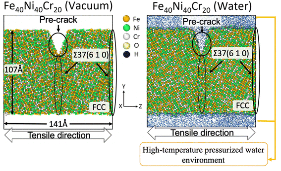 | ||
| Fig. 1 Tensile simulation model of FCC-type Fe40Ni40Cr20 alloy with a pre-crack at the Σ37 (610) grain boundary. A same grain boundary also appears at the cell edge. | ||
The above tensile simulations are conducted by using our originally developed MD simulator Laskyo.28 ReaxFF potential is used to describe the atomic interactions and chemical reactions. Here, the parameters for Fe/Cr/H2O system are picked directly from the previous studies.29,30 For the nickel, there are available parameters for Ni/Fe,31 whereas the parameters for Ni/Cr and Ni/H2O are lacking and hence should be developed in this research. Details regarding the parameter training methods and results are shown in the Fig. S2 of ESI.† Before tensile simulations, we perform relaxation simulation of the slab models in both vacuum and water environments at a temperature of 5 K and a pressure of 15 MPa, and then the temperature is slowly raised up to 600 K. In the MD tensile simulations, uniaxial tensile strain is applied to the z direction of each model with a constant strain rate of 109 s−1 and a timestep of 0.25 fs/step. All uniaxial tensile simulations are conducted for 400![[thin space (1/6-em)]](https://www.rsc.org/images/entities/char_2009.gif) 000 steps. Velocity-Verlet algorithm32,33 is used to evolve the atoms. The system temperature and pressure are controlled by the Nose–Hoover chain method.34 The simulation snapshots are viewed and created by the OVITO software.35
000 steps. Velocity-Verlet algorithm32,33 is used to evolve the atoms. The system temperature and pressure are controlled by the Nose–Hoover chain method.34 The simulation snapshots are viewed and created by the OVITO software.35
3. Results and discussion
Fig. 2 shows the stress–strain curves of Fe40Ni40Cr20 alloy during the tensile simulations in both vacuum and high-temperature/pressure water environment. As a consequence, we observe that the Fe40Ni40Cr20 alloy in vacuum shows a little lower elastic modulus (slope of the left-side elastic region) but higher ductility (stress value of the right-side plastic region) than those in water environment. Fig. 3 shows atomic shear strain of Fe40Ni40Cr20 alloy during tensile simulation in (a) vacuum and (b) high-temperature/pressure water environment. Initially, atomic strains in either vacuum or water environments are almost zero. In the case of vacuum, layered strain bands begin to generate from the grain boundary and surface at the strain of 5.50%, and then the layered shear bands become thick while more and more layered strain bands are generated at the tensile strain of 8.50%, as shown in Fig. 3a. In the case of high temperature and pressure water, atomic strains of the surface atoms become very large at the strain of 5.50% indicating a structural change of surface (Fig. 3b). Meanwhile, layered strain bands are not observed, while instead the atomic shear strain concentrate around the grain boundary. When the tensile strain increases to 8.50%, a large block of high-strain region is observed at the grain boundary. The above results demonstrate the different deformation mechanisms of Fe40Ni40Cr20 alloy in vacuum and water environments.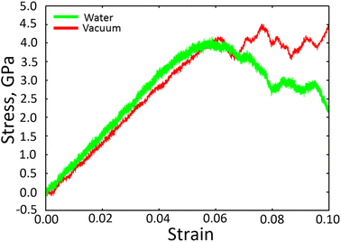 | ||
| Fig. 2 Stress–strain curve of Fe40Ni40Cr20 alloy in vacuum and high temperature/pressure water environments. | ||
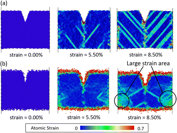 | ||
| Fig. 3 Atomic shear strain of Fe40Ni40Cr20 alloy in (a) vacuum and (b) high-temperature/pressure water environments. Non-reacted water molecules in (b) are invisible for clarity. | ||
To clarify the above different deformation mechanisms, the atomic structures are investigated in details. The atomic structure results of Fe40Ni40Cr20 alloy in vacuum are shown in Fig. 4a where the atoms in face-centered cubic (FCC), body-centered cubic (BCC), and hexagonal closest packed (HCP) phases are assigned to different colors. At the strain of 0.00%, atoms at the grain boundary could not be recognized as any of the FCC, BCC, and HCP phases so that they are named as “others”, while the rest atoms are recognized as FCC phase because the original Fe40Ni40Cr20 alloy model is of FCC structure. In vacuum, there are some layered HCP phases beginning to generate from the grain boundary and surface at the strain of 5.50%, and then these layered HCP phases propagate and become more and more thick with the increase of tensile strain, as shown in Fig. 4a. We suggest that the generation of these HCP phases are the origin of the layered shear bands in Fig. 3a because their positions are totally the same. According to the crystallography analysis, these HCP phases are generated by the Shockley partial dislocation in FCC phase.36 Fig. 5 schematically indicates the dislocation-induced phase transition from FCC (111) to HCP (001). In this illustration, blue, orange (both opaque and transparent ones), and red balls indicate the bottom, middle, and top layer atoms, respectively. For the normal FCC phase (right side of dislocation line), the top layer (red), middle layer (orange), and bottom layer (blue) are staggered with each other, and the black cube marks a typical FCC primitive cell where the opaque orange balls indicate the atoms of its (111) surface. When a Shockley partial dislocation is generated as shown in Fig. 5, the top layer (red) and middle layer (orange) atoms move downward with a Burgers vector of  where a is lattice constant, and hence the top layer (red) and bottom layer (blue) are overlapped becoming the HCP phase where the opaque orange balls indicate the atoms of its (001) surface. This illustration clearly shows the atomic mechanism of dislocation-induced phase transition from FCC (111) to HCP (001). Additionally, we found that these generated HCP layers are exactly parallel to the (111) surface of FCC matrix (see white lines in Fig. 3a), showing agreements with the above mechanism. In the case of high-temperature/pressure water environment, we observe the generation of BCC phase rather than HCP phase near the boundary at the strain of 5.50%. When the tensile strain increases to 8.50%, the BCC region becomes larger and larger, while a few layered HCP phases are generated from the boundary. These generated BCC and HCP phases are in the same positions with the areas of high atomic strain in Fig. 3b. We should notice that the water-induced change of deformation behavior (HCP layers to BCC blocks) is a universal behavior for Fe/Ni/Cr alloy, which is not affected by the change of element proportions. As the evidence, we have conducted tensile simulations of HEA with different element proportions (Fe30Ni30Cr40, Fe35Ni35Cr30, and Fe30Ni40Cr30), as shown in Fig. S3–S5 of ESI.† All HEA models show similar tensile deformation results as that of Fe40Ni40Cr20: layered HCP structures are generated in vacuum, whereas BCC phases are generated in water environment, confirming the universality of the above observed deformation mechanisms.
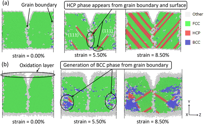 | ||
| Fig. 4 Atomic structures of Fe40Ni40Cr20 alloy in (a) vacuum and (b) high-temperature/pressure water environments. | ||
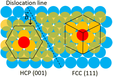 | ||
| Fig. 5 Schematic illustration of the FCC-to-HCP phase transition mechanism induced by Shockley partial dislocation. | ||
To clarify the unique deformation mechanism in water, we should first understand what happens at the alloy/water interface. Looking back the Fig. 3b and 4b again, it is noticed that the alloy surface in water becomes very rough while the atomic strains of surface atoms are very high. It is supposed that the alloy surface is oxidized by the chemical reactions with water molecules during tensile simulation. To verify this supposition, the numbers of chemical bonds including Fe–O, Ni–O, and Cr–O bonds are investigated as shown in Fig. 6. At the beginning of tensile simulation, the number of Cr–O, Fe–O, and Ni–O bonds are roughly 1850, 1200, and 700, respectively. This is because the alloy has been relaxed in water and the alloy surface is oxidized more or less before tensile simulation. As the numbers of Fe and Ni atoms are basically the same while the number of Cr atoms is only a half of Fe (and Ni) atoms in Fe40Ni40Cr20 alloy, we can conclude that Cr is most favorable to be oxidized following by Fe and Ni in sequence. This order of bond number corresponds to the electropositivity (antipode to electronegativity) of Cr, Fe, and Ni. With the proceeds of tensile simulation, the numbers of all Fe–O, Ni–O, and Cr–O bonds show a monotonic increasing trend, indicating a continuous oxidation of Fe40Ni40Cr20 alloy surface by the reactions with water. The next question is how the surface oxidation correlates to the change of deformation mechanism? In vacuum, we have reported that the Shockley partial dislocation generated from surface and grain boundary causes the FCC-to-HCP phase transition. Thus, in the case of corrosive water environment, since the alloy surface is covered and passivated by an oxidized layer, the generation of Shockley partial dislocations from oxidized surface is surely suppressed, so that the alloy has to find another deformation pathway (which does not start from the surface) to release the tensile stress and stored elastic energy. The FCC-to-BCC phase transition may take place as one of the possible deformation mechanisms, as schematically shown in Fig. 7. The blue-line cuboid in Fig. 6 is of FCC phase initially, and it becomes the primitive cell of BCC when tensile strain of  is applied to both x and y directions. To sum up the deformation mechanism in water, chemical reactions between water molecules and alloy surface cause the surface oxidization and suppress the generation of Shockley partial dislocation from surface as well as the dislocation-induced FCC-to-HCP phase transition, so that the occurrence of FCC-to-BCC phase transition is preferred to release the tensile stress. Additionally, we should notice that the generation of dislocation from grain boundary is still possible even though surface is oxidized, and this is the reason why we can observe the generation of HCP phase from grain boundary at high tensile strain of 8.50%.
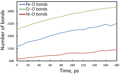 | ||
| Fig. 6 Time evolution of the number of Fe–O, Ni–O, and Cr–O bonds of Fe40Ni40Cr20 in high-temperature/pressure water environment. | ||
The changed deformation mechanism of Fe40Ni40Cr20 alloy may well explain the distinct stress–strain curves and the elastic/plastic properties in both vacuum and high-temperature/pressure water environment (Fig. 2). The higher elastic modulus in water environment is because the Fe40Ni40Cr20 alloy is difficult to deform via the FCC-to-HCP phase transition from surface by the surface oxidation. On the other hand, the lower ductility of Fe40Ni40Cr20 alloy in water environment is because BCC phase is generally more brittle than FCC and HCP phases. Overall, the presence of high-temperature/pressure water causes the surface oxidation of Fe40Ni40Cr20 alloy and hence changes the deformation mechanisms from FCC-to-HCP phase transition to FCC-to-BCC phase transition, which finally enhances the elastic modulus while reduce the ductility.
4. Conclusion
In this work, uniaxial tensile simulations of FCC-type Fe40Ni40Cr20 alloy (as a simplified model of HEAs) are conducted in vacuum and high-temperature/pressure water environment to clarify the effect of corrosive environment on the deformation mechanisms. In vacuum, layered HCP phases are formed from FCC matrix during tensile simulation due to the generation of Shockley partial dislocations from surface and grain boundary. While, in the corrosive water environment, alloy surface is oxidized by the reactions with water and this oxidized surface layer can suppress the generation of Shockley partial dislocation as well as the resulted FCC-to-HCP phase transition; instead, generation of BCC phase is preferred to release the tensile stress and stored elastic energy, leading to an enhanced elastic modulus and reduced ductility. Thus, we revealed that the deformation mechanism of Fe40Ni40Cr20 alloy is changed by the presence of high-temperature/pressure water environment—from FCC-to-HCP phase transition in vacuum to FCC-to-BCC phase transition in water. This study as a theoretical fundamental may contribute to the further improvement of HEAs with high resistance to SCC in experiments.Conflicts of interest
There are no conflicts to declare.Acknowledgements
This research was supported by Japan Society for the Promotion Science (JSPS) Grant-in-Aid for Scientific Research on Innovative Areas “High Entropy Alloys” (Grant No. 18H05453), Scientific Research (B) (Grant No. 21H01235), Scientific Research (C) (Grant No. 19K05380 and 20K05147), and Research Fellow (Grant No. 19J21195), and by Japan Science and Technology Agency CREST (Grant No. JPMJCR2191). We gratefully acknowledge the Center for Computational Materials Science (CCMS, Tohoku University) for the use of Materials science Supercomputing system for Advances Multi-scale Simulations towards Next-generation – Institute for Materials Research (MASAMUNE-IMR) (Proposal No. 19S0506, 20S0509, and 202012-SCKXX-0502).References
- J. W. Yeh, S. K. Chen, S. J. Lin, J. Y. Gan, T. S. Chin, T. T. Shun, C. H. Tsau and S. Y. Chang, Nanostructured high-entropy alloys with multiple principal elements: Novel alloy design concepts and outcomes, Adv. Eng. Mater., 2004, 6, 299–303 CrossRef CAS.
- D. B. Miracle and O. N. Senkov, A critical review of high entropy alloys and related concepts, Acta Mater., 2017, 122, 448–511 CrossRef CAS.
- M. H. Tsai and J. W. Yeh, High-entropy alloys: A critical review, Mater. Res. Lett., 2014, 2, 107–123 CrossRef.
- Y. Zhang, T. T. Zuo, Z. Tang, M. C. Gao, K. A. Dahmen, P. K. Liaw and Z. P. Lu, Microstructures and properties of high-entropy alloys, Prog. Mater. Sci., 2014, 61, 1–93 CrossRef CAS.
- J. Dong, X. Feng, X. Hao and W. Kuang, The environmental degradation behavior of FeNiMnCr high entropy alloy in high temperature hydrogenated water, Scr. Mater., 2021, 204, 114127 CrossRef CAS.
- S. Mizumachi, M. Koyama, Y. Fukushima and K. Tsuzaki, Growth behavior of a mechanically long fatigue crack in an FeCrNiMnCo high entropy alloy: A comparison with an austenitic stainless steel, ISIJ Int., 2020, 60, 175–181 CrossRef CAS.
- K. V. S. Thurston, B. Gludovatz, A. Hohenwarter, G. Laplanche, E. P. George and R. O. Ritchie, Effect of temperature on the fatigue-crack growth behavior of the high-entropy alloy CrMnFeCoNi, Intermetallics, 2017, 88, 65–72 CrossRef CAS.
- M. S. Daw, S. M. Foiles and M. I. Baskes, The embedded-atom method: A review of theory and applications, Mater. Sci. Rep., 1993, 9, 251–310 CrossRef CAS.
- M. I. Baskes, Modified embedded-atom potentials for cubic materials and impurities, Phys. Rev. B: Condens. Matter Mater. Phys., 1992, 46, 2727–2742 CrossRef CAS PubMed.
- S. Li, X. Ding, J. Deng, T. Lookman, J. Li, X. Ren, J. Sun and A. Saxena, Superelasticity in bcc nanowires by a reversible twinning mechanism, Phys. Rev. B: Condens. Matter Mater. Phys., 2010, 82, 205435 CrossRef.
- A. Ojha, H. Sehitoglu, L. Patriarca and H. J. Maier, Twin migration in Fe-based bcc crystals: Theory and experiments, Philos. Mag., 2014, 94, 1816–1840 CrossRef CAS.
- A. C. T. van Duin, S. Dasgupta and F. Lorant, ReaxFF: A reactive force field for hydrocarbons, J. Phys. Chem. A, 2001, 105, 9396–9409 CrossRef CAS.
- T. P. Senftle, S. Hong, M. M. Islam, S. B. Kylasa, Y. Zheng, Y. K. Shin, C. Junkermeier, R. Engel-Herbert, M. J. Janik, H. M. Aktulga, T. Verstraelen, A. Grama and A. C. T. van Duin, The ReaxFF reactive force-field: Development, applications and future directions, Npj Comput. Mater., 2016, 2, 15011 CrossRef CAS.
- Y. Wang, N. Yamada, J. Xu, J. Zhang, Q. Chen, Y. Ootani, Y. Higuchi, N. Ozawa, M.-I. de Barros Bouchet, J. M. Martin, S. Mori, K. Adachi and M. Kubo, Triboemission of hydrocarbon molecules from diamond-like carbon friction interface induces atomic-scale wear, Sci. Adv., 2019, 5, eaax9301 CrossRef CAS PubMed.
- Y. Wang, Y. Su, J. Zhang, Q. Chen, J. Xu, S. Bai, Y. Ootani, N. Ozawa, M.-I. de Barros Bouchet, J. M. Martin, K. Adachi and M. Kubo, Reactive molecular dynamics simulations of wear and tribochemical reactions of diamond like carbon interfaces with nanoscale asperities under H2 gas: Implications for solid lubricant coatings, ACS Appl. Nano Mater., 2020, 3, 7297–7304 CrossRef CAS.
- Y. Wang, J. Xu, Y. Ootani, N. Ozawa, K. Adachi and M. Kubo, Proposal of a new formation mechanism for hydrogenated diamond-like carbon transfer films: Hydrocarbon-emission-induced transfer, Carbon, 2019, 154, 7–12 CrossRef CAS.
- Y. Wang, K. Yukinori, R. Koike, Y. Ootani, K. Adachi and M. Kubo, Selective wear behaviors of a water-lubricating SiC surface under rotating-contact conditions revealed by large-scale reactive molecular dynamics simulations, J. Phys. Chem. C, 2021, 125, 14957–14964 CrossRef CAS.
- Y. Wang, J. Xu, Y. Ootani, N. Ozawa, K. Adachi and M. Kubo, Non-empirical law for nanoscale atom-by-atom wear, Adv. Sci., 2021, 8, 2002827 CrossRef CAS PubMed.
- J. Zhang, Y. Wang, Q. Chen, Y. Su, J. Xu, Y. Ootani, N. Ozawa, K. Adachi and M. Kubo, Graphitization dynamics of DLC under water lubrication revealed by molecular dynamics simulation, J. Comput. Chem., Jpn., 2019, 18, 103–104 CrossRef CAS.
- Q. Chen, J. Zhang, Z. Liu, Y. Wang, Y. Ootani, J. Xu, N. Ozawa and M. Kubo, Heterogeneous yielding mechanisms of body centered cubic iron for high resistance to chemical reaction-induced deterioration in supercritical water environments: A reactive molecular dynamics study, Scr. Mater., 2021, 202, 113997 CrossRef CAS.
- Y. Su, J. Zhang, Q. Chen, Y. Wang, N. Miyazaki, Y. Ootani, N. Ozawa and M. Kubo, A molecular dynamics study on alumina/carbon nanotube composite: How does annealing affect mechanical properties?, J. Comput. Chem., Jpn., 2019, 18, 259–262 CrossRef CAS.
- S. Monti, A. Corozzi, P. Fristrup, K. L. Joshi, Y. K. Shin, P. Oelschlaeger, A. C. T. van Duin and V. Barone, Exploring the conformational and reactive dynamics of biomolecules in solution using an extended version of the glycine reactive force field, Phys. Chem. Chem. Phys., 2013, 15, 15062–15077 RSC.
- S. Keten, C. C. Chou, A. C. T. van Duin and M. J. Buehler, Tunable nanomechanics of protein disulfide bonds in redox microenvironments, J. Mech. Behav. Biomed. Mater., 2012, 5, 32–40 CrossRef CAS PubMed.
- K. Chenoweth, S. Cheung, A. C. T. van Duin, W. A. Goddard and E. M. Kober, Simulations on the thermal decomposition of a poly(dimethylsiloxane) polymer using the ReaxFF reactive force field, J. Am. Chem. Soc., 2005, 127, 7192–7202 CrossRef CAS PubMed.
- G. M. Odegard, B. D. Jensen, S. Gowtham, J. Wu, J. He and Z. Zhang, Predicting mechanical response of crosslinked epoxy using ReaxFF, Chem. Phys. Lett., 2014, 591, 175–178 CrossRef CAS.
- F. Otto, A. Dlouhý, C. Somsen, H. Bei, G. Eggeler and E. P. George, The influences of temperature and microstructure on the tensile properties of a CoCrFeMnNi high-entropy alloy, Acta Mater., 2013, 61, 5743–5755 CrossRef CAS.
- Z. Wu, H. Bei, G. M. Pharr and E. P. George, Temperature dependence of the mechanical properties of equiatomic solid solution alloys with face-centered cubic crystal structures, Acta Mater., 2014, 81, 428–441 CrossRef CAS.
- J. Xu, Y. Higuchi, N. Ozawa, K. Sato, T. Hashida and M. Kubo, Parallel large-scale molecular dynamics simulation opens new perspective to clarify the effect of a porous structure on the sintering process of Ni/YSZ multiparticles, ACS Appl. Mater. Interfaces, 2017, 9, 31816–31824 CrossRef CAS PubMed.
- T. Pan and A. C. T. van Duin, Steel surface passivation at a typical ambient condition: Atomistic modeling and X-ray diffraction/reflectivity analyses, Electrocatalysis, 2011, 2, 307–316 CrossRef CAS.
- Y. K. Shin, H. Kwak, A. v. Vasenkov, D. Sengupta and A. C. T. van Duin, Development of a ReaxFF reactive force field for Fe/Cr/O/S and application to oxidation of butane over a pyrite-covered Cr2O3 catalyst, ACS Catal., 2015, 5, 7226–7236 CrossRef CAS.
- Y. K. Shin, H. Kwak, C. Zou, A. van Vasenkov and A. C. T. van Duin, Development and validation of a ReaxFF reactive force field for Fe/Al/Ni alloys: Molecular dynamics study of elastic constants, diffusion, and segregation, J. Phys. Chem. A, 2012, 116, 12163–12174 CrossRef CAS PubMed.
- L. Verlet, Computer “experiments” on classical fluids. I. thermodynamical properties of Lennard-Jones molecules, Phys. Rev., 1967, 159, 98–103 CrossRef CAS.
- L. Verlet, Computer “experiments” on classical fluids. II. equilibrium correlation functions, Phys. Rev., 1968, 165, 201–214 CrossRef.
- D. J. Evans and B. L. Holian, The Nose-Hoover thermostat, J. Chem. Phys., 1985, 83, 4069–4074 CrossRef CAS.
- A. Stukowski, Visualization and analysis of atomistic simulation data with OVITO–the Open Visualization Tool, Modell. Simul. Mater. Sci. Eng., 2009, 18, 015012 CrossRef.
- X. S. Yang, S. Sun, H. H. Ruan, S. Q. Shi and T. Y. Zhang, Shear and shuffling accomplishing polymorphic fcc γ → hcp ε → bct α martensitic phase transformation, Acta Mater., 2017, 136, 347–354 CrossRef CAS.
Footnotes |
| † Electronic supplementary information (ESI) available. See DOI: https://doi.org/10.1039/d2ra07039a |
| ‡ These authors contributed equally to this work. |
| This journal is © The Royal Society of Chemistry 2023 |

