 Open Access Article
Recovery of FLiBe from ThF4–FLiBe salt using precipitation–distillation coupled method
Yan Luo abc,
Jianxing Daiab,
Qiang Douabc,
Haiying Fu
 *abc and
Qingnuan Li*abc
aShanghai Institute of Applied Physics, Chinese Academy of Sciences, Shanghai, 201800, China. E-mail: fuhaiying@sinap.ac.cn; liqingnuan@sinap.ac.cn
bCAS Innovative Academies in TMSR Energy System, Chinese Academy of Sciences, Shanghai, 201800, China
cUniversity of Chinese Academy of Sciences, Beijing, 100049, China
First published on 27th February 2023
Abstract
The low-pressure distillation of FLiBe salt containing ThF4 was carried out at 1223 K and <10 Pa using thermogravimetric equipment. The weight loss curve indicated a rapid distillation stage at the beginning of distillation, followed by a slow stage. The composition and structure analyses showed that the rapid distillation process originated from the evaporation of LiF and BeF2, while the slow distillation process was mainly attributed to the evaporation of ThF4 and LiF complexes. Precipitation–distillation coupled method was employed for the recovery of FLiBe carrier salt. XRD analysis indicated that ThO2 was formed and remained in the residue with the addition of BeO. Our results showed that the combination of precipitation and distillation treatment was an effective way to recover carrier salt.
Introduction
Thorium, as an alternative nuclear fuel to uranium, has attracted growing concern all over the world.1 Natural thorium is a fertile material and can convert to fissile nuclide 233U by absorbing neutrons. The molten salt reactor (MSR) is considered one of the most suitable type of reactors for utilizing the Th–U fuel cycle. They usually apply liquid fuel which shows the great promise of inherent safety and excellent neutron economy, as well as on-line reprocessing.2,3 The Th–U fuel breeding can be achieved so that an efficient molten salt reprocessing system is involved to recover UF4, ThF4, and valuable carrier salts.Low-pressure distillation has potential application in the processing of molten salt for recovery of valuable 7LiF. Wang et al.4 observed the evaporation behaviors of rare earth-doped FLiNaK melts during low-pressure distillation. The decontamination factors (DFs) of typical rare earth elements were deduced to be approximately 103. To improve the decontamination factor by low-pressure distillation, pretreatment was performed, such as by the addition of oxidant or phosphorylation precipitation.5,6 However, a limited amount of data was obtained with LiF–BeF2–ThF4 solute fluoride systems. Results obtained for the system LiF–BeF2–ThF4–LaF3 (36.6–1.0–59.6–2.8 mol%) revealed that the relative volatility of ThF4 with respect to LiF at 1273 K was 0.25. Data acquired for the system of LiF–BeF2–ThF4–CsF–RbF (33.0–0.66–63.1–1.36–1.98 mol%) yielded relative volatility of about 0.65 for ThF4 at 1273 K.7 These results indicated that ThF4 had a greater tendency to evaporate than REFs. In our previous work, we showed that ThF4 co-evaporated with alkali-metal fluorides in the FLiNaK–ThF4 fuel composition during low-pressure distillation.8 However, FLiBe was used as an MSR coolant and fuel carrier salt. Generally, the F− ions in FLiBe were different from those in FLiNaK, which resulted in a different effect on the evaporation behavior of ZrF4.9 Thus, the applicability of distillation technology to the processing of FLiBe containing ThF4 was further assessed in the present work.
In this paper, the evaporation behavior of the LiF–BeF2–ThF4 system by low-pressure distillation was investigated using thermogravimetric equipment. To better understand the process, residues of several samples were taken during the course of the run and were subsequently analyzed for composition and structure phase. Furthermore, the precipitation of ThF4 by a reaction with BeO was investigated to explore the possibility of recovering carrier salt.
Experimental
Reagents
ThF4 (purity 99.99%) was prepared by Chang-Chun Institute of Applied Chemistry, Chinese Academy of Sciences. BeF2 (99.9%) and BeO (99.9%) were provided by the Hengsheng beryllium Industry Co., Ltd, Xinjiang. LiF (99%) was purchased from Shanghai Zhongli Industry Co., Ltd.Equipment
Thermogravimetric (TG) equipment was used to study the evaporation behavior of the salt during low-pressure distillation. The distillation equipment was composed of a molybdenum tube (Φ 45 mm, h 650 mm), a load cell with a precision of 0.0001 g in the range of 0–100 g, an electric heater with a precision of 1 K in the range of 293–1373 K, a nickel crucible, a thermal radiation shield, and a pump. Details of these settings are described elsewhere.9 All experiments were carried out in a dry glove box under an argon atmosphere (O2/H2O <5 ppm).Preparation of melt salt
LiF–BeF2 (66.7–33.3 mol%) eutectics were provided by the Shanghai Institute of Applied Physics, Chinese Academy of Sciences.10 Since LiF–ThF4 was more easily dissolved in FLiBe, the molten salt of LiF–ThF4 was prepared first.11 About 2.8 g of LiF was mixed with 10.2 g of ThF4 in a nickel crucible with a diameter of 2.5 cm. The mixture was then loaded into an electrical furnace at 973 K for 5 h to prepare the LiF–ThF4 (77–23 mol%) melt salt. After that, 5 g LiF–BeF2 (66.7–33.3 mol%) was mixed with 10 g of LiF–ThF4 melt under the same conditions to prepare 10 mol% ThF4–LiF–BeF2 melt salt. The electrical furnace was connected with an argon-covered glove box.Low-pressure distillation
A certain amount of 10 mol% ThF4–FLiBe was loaded in a nickel crucible and put on the load cell. In general, the evaporation area was constant. We used a nickel crucible with a 0.9 cm diameter and a surface area of ∼0.63 cm2. The thermogravimetric equipment was set in a glove box under an argon atmosphere. Evaporating zones were heated to 823 K with a heating rate of 10 K min−1 and maintained at 823 K for 40 min. After that, it was increased to 1223 K at a rate of 10 K ·min−1. When the temperature reached 1223 K, distillation was initiated by evacuating the system. Throughout the distillation process, the pressure was kept at about 10 Pa. The weight loss of loaded salt was monitored in situ by the load cell. Distillation was terminated by the addition of argon at the target time. To investigate the process of weight loss for each component of the melts in more detail, salt that remained in the nickel crucible was sampled during the course of the run at intervals of approximately 20 min; it was subsequently analyzed for Li, Be, and Th by ICP-OES.Precipitation–distillation coupled method
The precipitation process was performed by adding BeO in ThF4–LiF–BeF2. This possible conversion reaction generated was carried out according to eqn (1). To completely convert ThF4 to non-volatile oxide form (ThO2), the precipitation experiments were conducted at 1223 K for about 2 h with sufficient BeO, then distillation treatment was carried out. The remaining species were analyzed by powder X-ray diffraction (XRD).| ThF4 + 2BeO → ThO2 + 2BeF2 | (1) |
Analytical method
The concentration of Li, Be, and Th in the condensate and the residue were determined by ICP-OES (Optima 8000, PerkinElmer Co. USA). Each sample was analyzed three times and the relative error of parallel samples were below 5%. XRD with CuKa radiation (PANalytical, DY3614, Netherlands) was used for the qualitative measurement and phase analysis of samples. The sample was grounded to powder with a particle size of less than 20 μm and filled in a slotted flat glass plate. The glass plate was covered with plastic wrap to avoid moisture. The diffraction patterns were obtained over a 2θ range of 10–90° with a step size of 0.02°. During the analysis, the voltage and the current density were maintained at 40 kV and 40 mA, respectively, at ambient temperature.Molecular dynamics (MD) simulation
The local structure around Th4+ ions in the molten state was investigated by MD simulations with a polarizable force field. The ThF4–FLiBe mixture salts with different ThF4 concentrations were studied. The simulation details and the interaction potential were referred to from the literature.12 The MD simulations were performed using the CP2K software package.13 The radial distribution functions (RDFs) were used to describe the density change of surrounding ions as a function of distance. The coordination number (CN) of each ion was obtained from RDFs by doing a simple integration using eqn (2).
 | (2) |
In eqn (2), rmin was the distance corresponding to the first minimum of the radial distribution function (RDF).
Results and discussion
Evaporation behavior of 10 mol% ThF4–FLiBe
The evaporation process was recorded successfully by the load cell as Fig. 1(a). About 1.0 g of 10 mol% ThF4–FLiBe and FLiBe salt could be completely evaporated. The residue weight was negligible. However, it took 40 min to evaporate 1 g of FLiBe, while for 10 mol% ThF4–FLiBe, 120 min were needed. The evaporation rate is further compared in Fig. 1(b), where it can be seen that the maximum rate of FLiBe was 0.06 g min−1 and then slowly decreased to 0.02 g min−1, where it maintained itself for some time. However, the maximum rate for 10 mol% ThF4–FLiBe was only 0.02 g min−1. It went down to 0.005 g min−1 for a long time. With the addition of ThF4 in FLiBe, ThF4 evaporated with FLiBe, but the rate of ThF4–FLiBe evaporation slowed down by a factor of 3 as compared with FLiBe.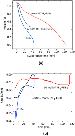 | ||
| Fig. 1 (a) Weight loss curves, (b). Rate curves for FLiBe, 10 mol% ThF4–FLiBe and BeO + 10 mol% ThF4–FLiBe at 1223 K and 10 Pa. | ||
A similar result was obtained during the distillation of ThF4–FLiNaK.8 In that case, with the addition of ThF4 in FLiNaK, the rate slowed down by a factor of 20. As discussed in our previous study, the rate decreased possibly due to the complexion of ThF4. We could also note the difference between the FLiNaK system and the FLiBe system. The inhibitory effect was even stronger in FLiNaK than in the FLiBe system. The reason was the different activity of F− ions in these melts, which affected the affinity of ThF4 toward the solvents.9 Alkali fluorides molten salts in FLiNaK were almost fully dissociated, and the F− ions activity in these solvents was approximated to be 1. The concentration of F− ions was relatively high in FLiNaK, resulting in strong bonding and solvation of thorium. P. Soucek et al.14 studied that the ThF4 activity coefficient in the LiF–CaF2 melt was about 4 orders of magnitude higher than in the LiF–NaF–KF eutectic melts. Similar results were obtained for ZrF4–FLiNaK and ZrF4–FLiBe.9 The experimental results implied that the evaporation behavior of the carrier salt changes with the addition of ThF4. To better understand the reasons, the details of the weight loss process for the various components in the ThF4–FLiBe mixture should be investigated.
Composition evolution during low-pressure distillation
In a multi-component salt, higher evaporation of one component in comparison with the others causes a change in the composition of the residue. Seven samples in the residue were taken during the course of the run at intervals of approximately 15–20 min and were analyzed for Li, Be, and Th. The composition evolution during low-pressure distillation is summarized in Table 1. One of the most concise ways to express the separation performance of the LiF and component i was to convert the condensate analyses to effective relative volatility with respect to LiF as the eqn (3). The effective volatility of component i with respect to LiF was defined as:
 | (3) |
| Evaporation time point (min) | Evaporation ratio (%) | Mole mass (mmol) | Mole fraction (%) | ||||
|---|---|---|---|---|---|---|---|
| LiF | BeF2 | ThF4 | LiF | BeF2 | ThF4 | ||
| 0 | 0 | 11.5 | 5.56 | 1.58 | 61.70 | 29.8 | 8.48 |
| 15 | 23.92 | 10.3 | 1.03 | 1.56 | 79.91 | 7.99 | 12.10 |
| 30 | 28.13 | 9.07 | 0.77 | 1.56 | 79.56 | 6.75 | 13.68 |
| 50 | 39.10 | 6.2 | 0.044 | 1.54 | 79.65 | 0.57 | 19.78 |
| 70 | 50.48 | 1.97 | 0.041 | 1.51 | 55.95 | 1.16 | 42.89 |
| 80 | 55.68 | 1.07 | 0.035 | 1.41 | 42.54 | 1.39 | 56.06 |
| 95 | 67.31 | 0.56 | 0.024 | 1.06 | 33.94 | 1.46 | 64.59 |
Although the composition of each component in the condensate was not measured directly during the run, the date allowed the composition of the condensate to be estimated from the material balance for each component.
From the beginning of the distillation to evaporation ratio of 23.92%, the mole fraction of LiF and BeF2 in the residue was 79.91% and 7.99%, respectively. The mole mass and mole mass fractions of LiF and BeF2 in the condensate were calculated by the subtraction method between the two time points. According to eqn (3), the average relative volatility of BeF2 during this run exhibited an average value of 37.8, which was higher than those reported by Hightower15 and Cantor.16,17 Hightower used an equilibrium still method to obtain a value of 4.71. Cantor used the transpiration method to obtain a value of 4.28 for LiF–BeF2 (85–15 mole%) at 1273 K and 3.75 for LiF–BeF2 (90–10 mole%). But after a time, the evaporation of BeF2 slowed down with an average value of 2.5 during the evaporation ratio from 23.92% to 28.13%. On the other hand, ThF4 was a little volatile at the beginning of the experiment with an average relative volatility of 0.01 before the evaporation ratio became 50.48%. However, ThF4 exhibited an average value of 0.17 as it moved from the evaporation ratio of 50.48% to 67.31%. Note that the ThF4 mole ratio in this salt increased from 42.89% to 64.59%. As reported by Smith,7 results obtained for the system LiF–BeF2–ThF4 gave the relative value of ThF4 αThF4–LiF at 1273 K in the range of 0.014 to 0.26 which is dependent on the concentration of ThF4. For example, Smith7 obtained values of 0.014 for LiF–BeF2–ThF4 (68–20–12 mol%) at 1273 K and 0.26 for LiF–BeF2–ThF4 (34–1.0–65 mol%). The relative volatility of ThF4 (with respect to LiF) obtained in our experiments with LiF–BeF2–ThF4 systems was in reasonable agreement with those reported by Smith when ThF4 content was the same.
As we know, low-pressure distillation is a dynamic process in which the less volatile components are constantly concentrated, leading to variations in the composition of the residue. On the other hand, variations in the composition of the liquid may cause large changes in the relative volatility value as well.
As can be seen from Table 1, from the beginning to the evaporation ratio of 23.92%, the mole fraction of BeF2 sharply decreased from 5.56 mmol to 1.03 mmol, while LiF exhibited a slight decrease from 11.5 mmol to 10.3 mmol and ThF4 barely changed. The reaction went on, and the evaporation ratio increased from 28.13% to 39.10%, and the moles of salts that decreased mainly belong to LiF. During this stage, BeF2 was negligible, while no significant evaporation of ThF4 happened. When the evaporation ratio increased from 50.48% to 67.31%, LiF evaporated slowly, together with ThF4. Therefore, it was not feasible to separate LiF from ThF4.
Structure evolution during low-pressure distillation
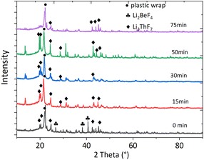
It is widely acknowledged that physicochemical properties are affected by compositions that affect structural aspects. With the addition of ThF4 to the FLiBe system, ThF4 might coordinate with F− ions to form a series of ThxFy4x–y. To understand how the molten mixture was organized in residue, XRD technology was used to characterize the different species involved in the molten phase. The chemical formula and the phase were detected by XRD analysis based on Xpert High score plus an analysis database (Fig. 2). Careful observation of the recorded XRD pattern suggest that the feed salt was identified as Li3ThF7 by the JCPDS number (ICSD 01-084-1903) and a minor phase Li2BeF4 was also detected, which matched with the JCPDS number (ICSD 01-076-2305). After 15 minutes of distillation, the room temperature XRD pattern did not give any indication of the presence of the BeF2 phase, probably because of its low concentration. The Li3ThF7 phase still could be detected. The deceleration of the evaporation rate was probably due to the complexation of the alkali-metal fluorides with ThF4. The clusters formed a network structure that existed as a block to affect the transport properties of the molten salt.These experimental efforts were accompanied by molecular dynamics (MD) simulation which proved to be an effective method for structure research and dynamics study at the microscopic scale and supplemented the experimental results.
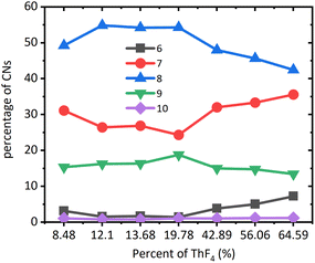
MD simulation could accurately describe the structure of molten salts, such as coordination numbers (CNs). The coordination numbers of Th–F were in the range of 6–10 as reported in Fig. 3. For the systems at all concentrations, the 8-coordination was dominant, followed by the 7-coordination, and 9-coordination, while 6-coordination and 10-coordination were negligible. After the mole ratio of ThF4 reached 20%, CN of 7 began to increase, while CN of 8 and 9 began to decrease. This means the network tended to dissociate and big clusters turned into smaller ones. The higher the percentage of the network formed, the more were the transport properties of the molten salt affected. In the beginning, the F− ions were relatively high resulting in strong bonding of thorium to form a network structure that was centered at Th4+. However, BeF2 also had an affinity for F− ions. Both media contained higher valence cations with high affinity towards F− ions. Be2+ cluster surrounded by F− ions was more likely to evaporate and left Th4+ clusters behind. Due to a decrease in the F− ions, part of the Th4+ network breaks down, and some F− ions escape the constraint of the Th4+ network and develop into a lower CN environment.
Vapor pressure changes during low-pressure distillation
According to the kinetic theory of gases, the maximum rate of evaporation could be obtained by the following equation:
 | (4) |
From eqn (4), it could be seen that the rate of evaporation was positively related to the vapor pressure. Fig. 4 presented the vapor pressures of LiF, BeF2, and ThF4 obtained from the literature.18,19 According to thermochemical data of vapor pressures for pure elements, ThF4 was less likely to evaporate than LiF and BeF2. The vapor pressures of pure fluorides at 1273 K were LiF: 62 Pa, BeF2: 8645 Pa, and ThF4: 8.8 Pa.19–21 It was likely that the evaporation rate followed the order of BeF2 > LiF > ThF4.
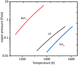 | ||
| Fig. 4 Vapor pressure of pure elements of fluorides data from ref. 18. | ||
As can be seen from Table 1, at the beginning of the evaporation, the evaporation rate followed the order of BeF2 > LiF > ThF4. However, after ThF4 was concentrated, LiF co-evaporated with ThF4. Smith et al.7 introduced the following eqn (5) which might account for this observation.
| PA = P0A × XA × γA | (5) |
PA0 was a constant, and XA was determined by ICP-OES as can be seen in Table 1. The activity was a product of mole fraction and activity coefficient. The lower the activity coefficient, the higher the affinity of the species to the solvent, and the more stable the species were in the solvent. Pratik Das22 calculated the activity of ThF4 over molten F1+3zLi1-zThxUy (z = x + y, 1 ≤ x ≤ 0, 0 ≤ y ≤ 1) salts phase as a partial value from excess Gibbs energy of the molten salts mixture. They showed that the activity of ThF4 remains constant up to xThF4 = 19.1 mol%, and afterwards it increased with a hump. This result was in good agreement with the MD simulation. After the molar ratio of ThF4 reached 20 mol%, the network tended to dissociate and big clusters turned into smaller ones that improved the activity of the molten salt. Both the activity and concentration of ThF4 increased in the later stage of distillation, and the apparent partial pressure increased according to eqn (4), thus ThF4 began to evaporate.
Precipitation coupled with distillation to recover pure carrier salt
We have obtained data on the negative influence of thorium on the recovery of carrier salt. The distillation rate decreased by 3 factors and thorium co-evaporated with carrier salts because of the complex. The results of this study showed that distillation may not be feasible as a primary separations method in the processing of carrier salts containing a large proportion of thorium. The studies of Oak Ridge National Laboratory (ORNL) demonstrated the chemical feasibility of oxide precipitation for removing protactinium, uranium, and rare earth elements from a fluoride mixture as oxides.23–25 The results showed that approximately 80% of the 233Pa activity was removed after the addition of ZrO2 and trace quantities of UF4 dissolved in LiF–BeF2–ThF4 (67–18–15 mol%) were precipitated using either ThO2 or BeO. To not cause serious alterations in the composition of the blanket material, the choice of precipitants was probably limited to BeO, ThO2, UO2, or possibly water vapor. The addition of oxides leads to another problem the increase in the amount of oxygen in the recycled molten salt. To solve the above-mentioned problems, precipitation by a reaction with BeO and a successive distillation method could be used. The effect of the addition of an oxide precipitant was determined by the equilibrium of the reaction of the oxide with the fluoride components. In this experiment, BeO was added as an oxide precipitant, and the equilibrium reaction was listed as eqn (1).The molar ratio of BeO to ThF4 was 2.5![[thin space (1/6-em)]](https://www.rsc.org/images/entities/char_2009.gif) :
:![[thin space (1/6-em)]](https://www.rsc.org/images/entities/char_2009.gif) 1 so BeO was in excess. The experiments in the molten salt were carried out on FLiBe alone, 10 mol% ThF4–FLiBe with the addition of BeO, and 10 mol% ThF4–FLiBe for comparison. As shown in Fig. 1, 10 mol% ThF4–LiF–BeF2 with the addition of BeO evaporated by half, and the reaction was terminated. The residue was analyzed by XRD indicating that ThO2 was formed in accordance with the JCPDS number (ICSD 03-065-0289) and excess BeO was left in accordance with the JCPDS number (ICSD 00-035-0818) as shown in Fig. 5. The Th concentration in the salt taken after the end of distillation was detected with ICP-OES. On this basis, the conversion ratio of ThF4 was over 99.9% indicating BeO to be quantitative. The Th and oxygen concentration in the recovered salt was below 100 μg g−1. Therefore, it was possible to recover FLiBe carrier molten salt using the precipitation-coupled method.
1 so BeO was in excess. The experiments in the molten salt were carried out on FLiBe alone, 10 mol% ThF4–FLiBe with the addition of BeO, and 10 mol% ThF4–FLiBe for comparison. As shown in Fig. 1, 10 mol% ThF4–LiF–BeF2 with the addition of BeO evaporated by half, and the reaction was terminated. The residue was analyzed by XRD indicating that ThO2 was formed in accordance with the JCPDS number (ICSD 03-065-0289) and excess BeO was left in accordance with the JCPDS number (ICSD 00-035-0818) as shown in Fig. 5. The Th concentration in the salt taken after the end of distillation was detected with ICP-OES. On this basis, the conversion ratio of ThF4 was over 99.9% indicating BeO to be quantitative. The Th and oxygen concentration in the recovered salt was below 100 μg g−1. Therefore, it was possible to recover FLiBe carrier molten salt using the precipitation-coupled method.
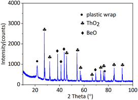 | ||
| Fig. 5 The XRD pattern of residue in 10 mol% ThF4–FLiBe with the addition of BeO after distillation. | ||
Conclusion
The evaporation behavior of FLiBe containing ThF4 was investigated using low-pressure distillation. The molten salt mixture evaporated rapidly at the beginning, followed by a long low-speed distillation zone. The rapid distillation rate originated mainly from the evaporation of LiF and BeF2 in the molten salt, while the evaporation of the complex formed from alkali-metal fluorides with ThF4 was responsible for low-speed distillation. The decrease in F− concentration in the residue caused an increase in ThF4 activity which led to the evaporation of the LixThyFz complex. The mixture was further treated using precipitation combined with the distillation method. It was found ThF4 was successfully converted to ThO2 and the purification of recovery salt was significantly improved. Our results suggested that it was an effective way to recover carrier salt by precipitation–distillation coupled method.Author contributions
Y. Luo: Conceptualization, investigation, methodology, writing - original draft. J. X. Dai: Software, formal analysis. Q. Dou: Project administration. H. Y. Fu: Writing - review & editing, data curation, supervision. Q. N. Li: Validation, supervision, funding acquisition.Conflicts of interest
We declare that we do not have any commercial or associative interest that represents a conflict of interest in connection with the work.Acknowledgements
This research was funded by the National Natural Science Foundation of China (No. 21771188, 12275349, 12175303).References
- IAEA, Technical report: IAEA-TECDOC-1450, 2005 Search PubMed
.
- T. Abram, Energy Policy, 2008, 36, 4323–4330 CrossRef
.
- J. E. Kelly, Prog. Nucl. Energy, 2014, 77, 240–246 CrossRef CAS
.
- Z. H. Wang, H. Y. Fu, Y. Yang, J. X. Geng, Y. P. Jia, D. D. Huang, W. X. Li, G. Yu, Q. N. Li and Q. Dou, J. Radioanal. Nucl. Chem., 2017, 311, 637–642 CrossRef CAS
.
- Y. Z. Cho, H. C. Yang, G. H. Park, H. S. Lee and I. T. Kim, J. Nucl. Mater., 2009, 384, 256–261 CrossRef CAS
.
- J. H. Choi, I. H. Cho, H. C. Eun, H. S. Park, Y. Z. Cho, K. R. Lee, G. I. Park, S. H. Kim, C. H. Shin and J. K. Kim, J. Radioanal. Nucl. Chem., 2014, 299(3), 1731–1738 CrossRef CAS
.
- F. J. Smith, L. M. Ferris and C. T. Thompson, ORNL-4415, Oak Ridge National Laboratory, 1969 Search PubMed
.
- Y. Luo, J. X. Geng, W. X. Li, H. Y. Fu, Q. Dou and Q. N. Li, J. Nucl. Mater., 2019, 525, 48–52 CrossRef CAS
.
- Y. Luo, J. Dai, Q. Dou, H. Y. Fu and Q. N. Li, J. Nucl. Mater., 2022, 561, 153550 CrossRef CAS
.
- Y. L. Song, M. Shen, H. Peng, C. Y. Wang, S. F. Zhao, Y. Zuo and L. D. Xie, J. Electrochem. Soc., 2020, 167, 023501 CrossRef CAS
.
- L. Sun, Y. Niu, C. Hu, X. H. Wang, Z. Q. Zhao, J. G. Chen, X. Z. Zhou, H. Y. Fu, Q. Dou and Q. N. Li, J. Fluorine Chem., 2022, 261–262, 110016 CrossRef CAS
.
- J. Dai, D. Long, P. Huai and Q. N. Li, J. Mol. Liq., 2015, 211, 747–753 CrossRef CAS
.
- CP2K software is freely available from http://cp2k.berlios.de/
.
- P. Soucek, D. Rodrigues and O. Beneš, Electrochim. Acta, 2021, 380, 138198 CrossRef CAS
.
- J. R. Hightower Jr and L. E. McNeese, ORNL-TM-2058, Oak Ridge National Laboratory, Tennessee, 1968 Search PubMed
.
- W. R. Grimes, Reactor Chem. Div. Ann. Progr. Rept. Dec. 31, 1966, ORNL-4076, Oak Ridge National Laboratory, 1963 Search PubMed
.
- R. B. Briggs, MSR Program Semiann. Rogr. Rept. ORNL-3936, Oak Ridge National Laboratory, 1966 Search PubMed
.
- C. L. Yaws, Handbook of Vapor Pressure: Volume 4: Inorganic Compounds and Elements, Gulf publishing Company, Houston, Taxas, 1994 Search PubMed
.
- A. J. Damell and F. J. Keneshea, J. Phys. Chem., 1958, 62(9), 1143–1145 CrossRef
.
- D. R. Stull, Ind. Eng. Chem., 1947, 39, 517–540 CrossRef CAS
.
- J. H. Simons, Fluorine Chemistry, Academic, New York, 1964, p. 20 Search PubMed
.
- P. Das, S. Mukherjee, R. Mishra and S. Dash, J. Fluorine Chem., 2019, 226, 109349 CrossRef CAS
.
- J. H. Shaffer, W. K. R. Finnell, F. A. Doss, W. P. Teichert and W. R. Grines, ORNL-3913, Oak Ridge National Laboratory, 1965, p. 41 Search PubMed
.
- H. G. Macpherson, Molten salt reactor program quarterly progress report For period ending January 31 and April 30, 1960, ORNL-2973, Oak Ridge National Laboratory, 1960, pp. 69–75 Search PubMed
.
- M. W. Rosenthal, R. B. Briggs and P. N. Haubenreich, Molten salt reactor program quarterly progress report for period
ending February 28, 1971, ORNL-4676, 1971, pp. 237–240 Search PubMed
.
| This journal is © The Royal Society of Chemistry 2023 |

