 Open Access Article
Performance improvement of aqueous zinc batteries by zinc oxide and Ketjen black co-modified glass fiber separators†
Gang Lin a,
Xiaoliang Zhou
 *ac,
Limin Liu*ac,
Huangmin Lia,
Di Huanga,
Jing Liua,
Jie Lia and
Zhaohuan Wei
 *b
*b
aCollege of Chemistry and Chemical Engineering, Southwest Petroleum University, Chengdu, 610500, PR China
bSchool of Physics, University of Electronic Science and Technology of China, Chengdu, 611731, PR China
cTianfu Yongxing Laboratory, Chengdu, PR China
First published on 23rd February 2023
Abstract
Rechargeable aqueous zinc-based batteries (AZBs) are intriguing candidates for next-generation energy storage batteries. However, the dendrites generated plagued their development during charging. To inhibit the dendrite generation, a novel modification method based on the separators was proposed in this study. The separators were co-modified by spraying sonicated Ketjen black (KB) and zinc oxide nanoparticles (ZnO) uniformly. The highly conductive KB homogenizes the anode interface's electric field. The deposited ions are deposited on ZnO preferentially rather than on the anode electrode, and the deposited particles can be refined. The ZnO in the uniform KB conductive network can provide sites for zinc deposition, and the by-products of the zinc anode electrode reduced. The Zn-symmetric cell with the modified separator (Zn//ZnO–KB//Zn) can cycle for 2218 h at 1 mA cm−2 stably (the unmodified Zn-symmetric cell (Zn//Zn) only can cycle for 206 h). With the modified separator, the impedance and polarization of Zn//MnO2 reduced, and the cell can charge/discharge 995 times at 0.3 A g−1. In conclusion, the electrochemical performance of AZBs can be improved effectively after separator modification by the synergistic effect of ZnO and KB.
1. Introduction
With increasing attention to environmental protection and growing energy demand, the research on sustainable energy storage devices is becoming urgent.1–4 Lithium-ion batteries have developed rapidly, but toxic and flammable electrolytes are extremely dangerous, so the non-toxic and safe aqueous zinc-based batteries have attracted a lot of attention in recent years.5–8 Zinc metal is relatively stable in aqueous electrolytes, so it can be used as the anode electrode of aqueous zinc-based batteries (AZBs) directly. In fact, Zn metal electrodes have many advantages, including:9–11 (1) high abundance and low price, (2) chemical stability, (3) high theoretical capacity (820 mA h g−1, 5855 mA h cm−2), and (4) low redox potential (−0.76 V vs. SHE). In AZBs, the Zn2+ ions are plating/stripping at the anode electrode during charging/discharging of AZBs, and the dendrites and side reaction endanger the lifespan and Coulomb efficiency of the batteries.12–14 Therefore, the improvement of Zn anode is essential for AZBs.Many modification strategies have been proposed to improve the reversibility of AZBs, such as modulating zinc coordination environment,15,16 uniforming the interfacial electric field,13,17 and inducing zinc deposition.18–21 However, most of these strategies focused on zinc anode and electrolyte. The interface between zinc anode and electrolyte is modified by those methods, but this interface is near the separator. Therefore, the interface between the separator and zinc anode also plays a very important role for the performance of AZB. In fact, there is not so much attention paid to the separator. Li et al. devised a Janus separator toward stabilizing Zn anode via directly growing vertical graphene (VG) carpet on one side of commercial glass fiber separator by means of plasma enhanced chemical vapor deposition.22 The conformal and uniform 3D VG conductive networks facing Zn anode could effectively homogenize electric field distribution and lower the local current density. On the other hand, the incorporation of oxygen and nitrogen dopants via a simple air plasma treatment would further boost the zincophilicity of VG carpet. Therefore, the Janus separator succeeded in regulating smooth Zn2+ transport, guiding uniform Zn deposition and hence delaying the dendritic formation. Su et al. designed a Janus separator by spray printing of conductive Ti3C2Tx MXene nanosheets over one side of commercial GF separator.23 The optimized dielectric constant of MXene-GF was significantly higher than that of bare GF, helping construct a directional built-in electrical field via Maxwell–Wagner effect to expedite Zn2+ migration, which afforded homogeneous interfacial ion fields. Meanwhile, the abundant surface groups of MXene ensured lower desolvation energy, accelerated Zn2+ diffusion, and restrained anion flux, thus aiding in dendrite-free deposition and mitigated corrosion.
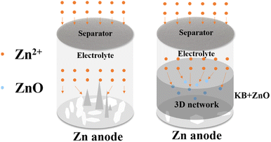
Inspired by the creative work above, we designed a Janus separator of AZBs to enhance the electrochemical performance by suppressing zinc dendrite. KB as a carbon material which has been proven to be effective for improving the conductivity of batteries, avoiding the “tip effect” by homogenizing the interfacial electric field of the Zn anode.17,21,24 The electrochemically inert nano zinc oxide (ZnO) has also been shown that the Zn2+ transfer and deposition kinetics can be accelerated via the electrostatic attraction to Zn2+.25 In this paper, we sprayed KB and ZnO on the surface of the separators to prepare a uniform modified layer. The zinc symmetric cells were assembled with the modified separators. Since the adsorption energy of ZnO for zinc atoms is stronger than that of the metal zinc, zinc ions were deposited on the modified layer of the separators preferentially, while avoiding deposition on the zinc anode electrode directly, as shown in Fig. 1. When the rate of ZnO and KB equals 6![[thin space (1/6-em)]](https://www.rsc.org/images/entities/char_2009.gif) :
:![[thin space (1/6-em)]](https://www.rsc.org/images/entities/char_2009.gif) 3 in mass, the modified zinc symmetrical cell can cycle 2218 h at 1 mA cm−2, which is almost 10 times longer than the symmetric cell with the unmodified separator. Meanwhile, the SEM and XRD results indicated that the modified layer could improve the zinc deposition environment and suppress the formation of dendrites effectively. With the modified separator, the electrochemical performance of Zn//MnO2 has been improved significantly. Therefore, the Janus separator modified by ZnO and KB can improve the electrochemical performance of the battery successfully.
3 in mass, the modified zinc symmetrical cell can cycle 2218 h at 1 mA cm−2, which is almost 10 times longer than the symmetric cell with the unmodified separator. Meanwhile, the SEM and XRD results indicated that the modified layer could improve the zinc deposition environment and suppress the formation of dendrites effectively. With the modified separator, the electrochemical performance of Zn//MnO2 has been improved significantly. Therefore, the Janus separator modified by ZnO and KB can improve the electrochemical performance of the battery successfully.
2. Experimental
2.1. Preparation of zinc electrode and electrolyte
Commercial zinc flakes with a thickness of 0.02 mm were purchased as the metal zinc anode electrode. The zinc flakes was polished by 1000 and 2000 grit SiC paper, then sonicated several times with deionized water and ethanol, and then dried in vacuum for 12 h. Finally, the zinc flakes were cut into circles about 12.7 mm in diameter before use.2.2. Modification of the separators
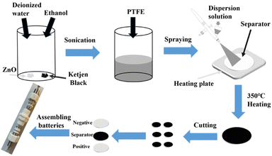
The processes of the separators modification are shown in Fig. 2. Nano ZnO (99.9%, 30 ± 10 nm) and commercial β-MnO2 (denoted as MnO2) were purchased from MACKLIN. The solution of deionized water and ethanol in a volume ratio of 1![[thin space (1/6-em)]](https://www.rsc.org/images/entities/char_2009.gif) :
:![[thin space (1/6-em)]](https://www.rsc.org/images/entities/char_2009.gif) 1 was prepared. ZnO, KB and polytetrafluoroethylene emulsion (PTFE) were added to the solution, in which the mass ratio of ZnO, KB and PTFE were 8
1 was prepared. ZnO, KB and polytetrafluoroethylene emulsion (PTFE) were added to the solution, in which the mass ratio of ZnO, KB and PTFE were 8![[thin space (1/6-em)]](https://www.rsc.org/images/entities/char_2009.gif) :
:![[thin space (1/6-em)]](https://www.rsc.org/images/entities/char_2009.gif) 1
1![[thin space (1/6-em)]](https://www.rsc.org/images/entities/char_2009.gif) :
:![[thin space (1/6-em)]](https://www.rsc.org/images/entities/char_2009.gif) 1; 7
1; 7![[thin space (1/6-em)]](https://www.rsc.org/images/entities/char_2009.gif) :
:![[thin space (1/6-em)]](https://www.rsc.org/images/entities/char_2009.gif) 2
2![[thin space (1/6-em)]](https://www.rsc.org/images/entities/char_2009.gif) :
:![[thin space (1/6-em)]](https://www.rsc.org/images/entities/char_2009.gif) 1; 6
1; 6![[thin space (1/6-em)]](https://www.rsc.org/images/entities/char_2009.gif) :
:![[thin space (1/6-em)]](https://www.rsc.org/images/entities/char_2009.gif) 3
3![[thin space (1/6-em)]](https://www.rsc.org/images/entities/char_2009.gif) :
:![[thin space (1/6-em)]](https://www.rsc.org/images/entities/char_2009.gif) 1; 5
1; 5![[thin space (1/6-em)]](https://www.rsc.org/images/entities/char_2009.gif) :
:![[thin space (1/6-em)]](https://www.rsc.org/images/entities/char_2009.gif) 4
4![[thin space (1/6-em)]](https://www.rsc.org/images/entities/char_2009.gif) :
:![[thin space (1/6-em)]](https://www.rsc.org/images/entities/char_2009.gif) 1, and sonicated 4 h. The mixture was sprayed uniformly on one side of the commercial separators (Whatman GF/A) by an airbrush while the separator was heated on a heating plate. After drying, the separators were heated at 350 °C for 2 h to activate the PTFE. Finally, the separators were cut into discs with a diameter of 12.7 mm. The thickness of ZnO and KB modified layer on the separator after spraying was about 112.5 μm, as shown in Fig. S2.† MnO2, acetylene black and PTFE were mixed in the same way, sprayed on the carbon paper and then activated to prepare the cathode electrode.
1, and sonicated 4 h. The mixture was sprayed uniformly on one side of the commercial separators (Whatman GF/A) by an airbrush while the separator was heated on a heating plate. After drying, the separators were heated at 350 °C for 2 h to activate the PTFE. Finally, the separators were cut into discs with a diameter of 12.7 mm. The thickness of ZnO and KB modified layer on the separator after spraying was about 112.5 μm, as shown in Fig. S2.† MnO2, acetylene black and PTFE were mixed in the same way, sprayed on the carbon paper and then activated to prepare the cathode electrode.
2.3. Electrochemical measurements
The symmetric cells were assembled with a simple device (Fig. S1†) with different separators and pro-treated zinc flakes as symmetrical electrodes, 1 M ZnSO4 as electrolyte. The cells were noted 1#, 2#, 3# and 4# by the modified separators with ZnO![[thin space (1/6-em)]](https://www.rsc.org/images/entities/char_2009.gif) :
:![[thin space (1/6-em)]](https://www.rsc.org/images/entities/char_2009.gif) KB
KB![[thin space (1/6-em)]](https://www.rsc.org/images/entities/char_2009.gif) :
:![[thin space (1/6-em)]](https://www.rsc.org/images/entities/char_2009.gif) PTFE = 8
PTFE = 8![[thin space (1/6-em)]](https://www.rsc.org/images/entities/char_2009.gif) :
:![[thin space (1/6-em)]](https://www.rsc.org/images/entities/char_2009.gif) 1
1![[thin space (1/6-em)]](https://www.rsc.org/images/entities/char_2009.gif) :
:![[thin space (1/6-em)]](https://www.rsc.org/images/entities/char_2009.gif) 1; 7
1; 7![[thin space (1/6-em)]](https://www.rsc.org/images/entities/char_2009.gif) :
:![[thin space (1/6-em)]](https://www.rsc.org/images/entities/char_2009.gif) 2
2![[thin space (1/6-em)]](https://www.rsc.org/images/entities/char_2009.gif) :
:![[thin space (1/6-em)]](https://www.rsc.org/images/entities/char_2009.gif) 1; 6
1; 6![[thin space (1/6-em)]](https://www.rsc.org/images/entities/char_2009.gif) :
:![[thin space (1/6-em)]](https://www.rsc.org/images/entities/char_2009.gif) 3
3![[thin space (1/6-em)]](https://www.rsc.org/images/entities/char_2009.gif) :
:![[thin space (1/6-em)]](https://www.rsc.org/images/entities/char_2009.gif) 1; 5
1; 5![[thin space (1/6-em)]](https://www.rsc.org/images/entities/char_2009.gif) :
:![[thin space (1/6-em)]](https://www.rsc.org/images/entities/char_2009.gif) 4
4![[thin space (1/6-em)]](https://www.rsc.org/images/entities/char_2009.gif) :
:![[thin space (1/6-em)]](https://www.rsc.org/images/entities/char_2009.gif) 1, respectively. The symmetric cell assembled with unmodified separator was noted as 5#. The simple device was completely symmetrical, mainly composed of 304L stainless steels, straight-through, and circular clamps (both through-through and clamps are made of PTFE), which were put zinc|separator|zinc into the device in turn, and then the electrolyte was added and the device was tightened for testing. MnO2 and metal zinc were used as the cathode and anode electrodes for Zn//MnO2, 1 M ZnSO4 + 0.1 M MnSO4 as electrolyte, CR2032-type coin cells were assembled for electrochemical testing. The EIS analysis was performed with an electrochemical workstation (Reference 3000, Gamry, USA) in the frequency range of 1 MHz to 0.01 Hz with an AC signal amplitude of ±10 mV. Galvanostatic charge/discharge (GCD) was tested on a NEWARE multi-channel workstation (CT-4800T-5 V 10 mA, China) at 30 °C. The Cyclic Voltammetry (CV) test of Zn//MnO2 was tested at 0.5 mV s−1, and the voltage window was 1–1.8 V.
1, respectively. The symmetric cell assembled with unmodified separator was noted as 5#. The simple device was completely symmetrical, mainly composed of 304L stainless steels, straight-through, and circular clamps (both through-through and clamps are made of PTFE), which were put zinc|separator|zinc into the device in turn, and then the electrolyte was added and the device was tightened for testing. MnO2 and metal zinc were used as the cathode and anode electrodes for Zn//MnO2, 1 M ZnSO4 + 0.1 M MnSO4 as electrolyte, CR2032-type coin cells were assembled for electrochemical testing. The EIS analysis was performed with an electrochemical workstation (Reference 3000, Gamry, USA) in the frequency range of 1 MHz to 0.01 Hz with an AC signal amplitude of ±10 mV. Galvanostatic charge/discharge (GCD) was tested on a NEWARE multi-channel workstation (CT-4800T-5 V 10 mA, China) at 30 °C. The Cyclic Voltammetry (CV) test of Zn//MnO2 was tested at 0.5 mV s−1, and the voltage window was 1–1.8 V.
2.4. Materials characterization
The phases structure of the modified material of the separators and the surface of the zinc flakes were determined by X-ray diffractometer (XRD, Bruker D8 Advance). The surface micromorphology of the samples was studied by scanning electron microscopy (SEM) with X-ray spectroscopy (ZEISS GeminiSEM 300).3. Results and discussion
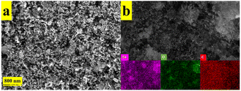
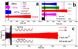
Fig. 3(a) showed the morphology of ZnO and KB after mixing, which the ZnO were distributed uniformly among the flakes of KB. And the EDS results also show the uniform distribution of KB and ZnO, as shown in Fig. 3(b). The formation of a 3D conductive network of KB after mixing could improve the conductivity of the material, which is beneficial to the cycling performance of the cells.26The cycling stability of the cells with different material modified separators is shown in Fig. 4(a), where 3# was the cells modified with KB and ZnO. When modified with ZnO and KB individually, the cells cycled 335 and 477 h, respectively, and when modified with ZnO and KB (ZnO![[thin space (1/6-em)]](https://www.rsc.org/images/entities/char_2009.gif) :
:![[thin space (1/6-em)]](https://www.rsc.org/images/entities/char_2009.gif) KB = 6
KB = 6![[thin space (1/6-em)]](https://www.rsc.org/images/entities/char_2009.gif) :
:![[thin space (1/6-em)]](https://www.rsc.org/images/entities/char_2009.gif) 3) together, the cells stably cycled for 2218 h. Fig. 4(b) shows the cycling stability of 1#, 2#, 3#, 4# and 5# at 1 mA cm−2 (0.5 mA h cm−2). 5# showed a voltage abnormality after 206 h, the cell failed afterwards, which indicates that the dendrites generated during the cell cycling had pierced the unmodified separator causing a short circuit. However, the cycling time of 1#, 2#, 3# and 4# was much longer, which cycled for 1291 h, 1489 h, 2218 h and 1206 h respectively. Among them, both 1#, 2# and 4# show voltage fluctuations during 500 h, and it recovered in the subsequent cycle, which indicates that the cells had a micro-short circuit in the cycling. And 3# shows a steady voltage from the beginning of the cycling to the cell failure. Meanwhile, the voltage hysteresis of 3# was smaller than that of 5#, as shown in the inset of Fig. 4(c), indicating the minor polarization of 3#.27 The galvanostatic cycling performance showed the ZnO–KB modified layer is effective for cells, and the best performance was obtained with ZnO
3) together, the cells stably cycled for 2218 h. Fig. 4(b) shows the cycling stability of 1#, 2#, 3#, 4# and 5# at 1 mA cm−2 (0.5 mA h cm−2). 5# showed a voltage abnormality after 206 h, the cell failed afterwards, which indicates that the dendrites generated during the cell cycling had pierced the unmodified separator causing a short circuit. However, the cycling time of 1#, 2#, 3# and 4# was much longer, which cycled for 1291 h, 1489 h, 2218 h and 1206 h respectively. Among them, both 1#, 2# and 4# show voltage fluctuations during 500 h, and it recovered in the subsequent cycle, which indicates that the cells had a micro-short circuit in the cycling. And 3# shows a steady voltage from the beginning of the cycling to the cell failure. Meanwhile, the voltage hysteresis of 3# was smaller than that of 5#, as shown in the inset of Fig. 4(c), indicating the minor polarization of 3#.27 The galvanostatic cycling performance showed the ZnO–KB modified layer is effective for cells, and the best performance was obtained with ZnO![[thin space (1/6-em)]](https://www.rsc.org/images/entities/char_2009.gif) :
:![[thin space (1/6-em)]](https://www.rsc.org/images/entities/char_2009.gif) KB = 6
KB = 6![[thin space (1/6-em)]](https://www.rsc.org/images/entities/char_2009.gif) :
:![[thin space (1/6-em)]](https://www.rsc.org/images/entities/char_2009.gif) 3.
3.
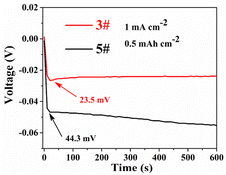
In order to study the influence of the separator modification layer on the reaction kinetics of the cells, we investigated the overpotential of the first discharge, and the overpotential represents the difficulty of zinc deposition. Fig. 5 shows the overpotentials of the first discharge of 3# and 5#, at 1 mA cm−2, the overpotentials of 5# and 3# were 44.3 and 23.5 mV, respectively. As shown in Fig. S3,† the overpotentials of 1#, 2#, 3# and 4# were smaller than that of 5#, and 3# always maintained the minimum overpotential. This indicates that zinc deposition became easier after the separator has been modified. This is most likely due to the fact that the modification of the separator can provide more nucleation sites for Zn ions, which can reduce the deposition barrier and promote the transfer of Zn ions.27–29
The charge/discharge performances of 3# and 5# with different current density were tested. The current density gradually increased from 0.1 mA cm−2 (0.05 mA h cm−2) to 2 mA cm−2 (1 mA h cm−2) for the first 100 h, and 1 mA cm−2 (0.5 mA h cm−2) after 100 h, as shown in Fig. 6. 5# short-circuited at 125 h (only 25 h at 1 mA cm−2 after different current densities) and the cell failed, due to the dendrites pierced the unmodified separator in the high current. And 3# cycled for 1116 hours at different current densities (1216 hours in total) with stable voltage and without micro-short circuits. The voltage hysteresis of 3# was less than that of 5#, because of the faster charge/mass transfer processes of 3#.27 In order to clarify that modified separator with ZnO and KB can improve the performance of zinc symmetric cells, the adsorption energy was calculated of different substrates for Zn deposition. According to the model calculated by density functional theory (DFT, Fig. 7), it is concluded that the adsorption energy of ZnO for Zn atoms (−0.5584 eV) is more negative than that of Zn for Zn atoms (−0.4866 eV). It indicated that Zn2+ tends to deposit at ZnO.27,30
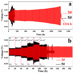 | ||
| Fig. 6 Charge/discharge performances of 3# and 5# at different current densities (0.1–2 mA cm−2) (a) overall, (b) locally. | ||
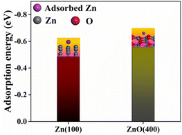 | ||
| Fig. 7 Adsorption energies of Zn atom on Zn (100) and ZnO (400). The insets are corresponding models. | ||
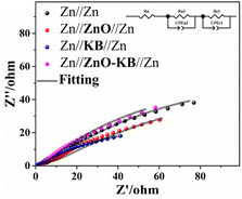
The EIS analysis of Zn//Zn, Zn//ZnO//Zn, Zn//KB//Zn, Zn//ZnO–KB//Zn (3#) is shown in Fig. 8. The Nyquist plots were fitted by the corresponding equivalent circuits, and the fitting results are shown in Table S1.† Re denotes the resistance of the electrolyte and is the intersection of the Nyquist plots with the real part in the high frequency region, Rs denotes the electrode interface (electrode/electrolyte interface) resistance, and the depressed semicircle in the low frequency region corresponds to Rct indicating the charge transfer capability.18,30 The Rct was reduced by the KB with high conductivity and increased by the inert ZnO, which was determined by the conductivity of the modified material. And the KB increased the charge transfer by improving the conductivity of the cells.
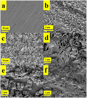
Fig. 9 shows the zinc flakes in different states. As shown in Fig. 9(a) is the SEM image of the surface of the pre-treated zinc flakes, which had a flat surface with only minor scratches caused by polishing. As shown in Fig. 9(b) is the SEM image of the zinc flakes which was immersed in 1 M ZnSO4 for 24 h, and a large number of petal-like deposits appeared on the surface of the zinc flakes. As shown in Fig. 9(c) is the surface morphology of the zinc anode electrode after cycling with unmodified separator. A large number of hexagonal zinc deposits appeared, and there was a risk of dendrite formation after long-term cycling.21,31 The surface of the zinc anode electrode was covered with hexagonal dendrites, as shown in Fig. 9(d). Similarity between the unmodified (c) and immersed (b) indicates that KB did not inhibit dendrites effectively. The SEM image of the zinc anode electrode surface after modification of the separator with ZnO is shown in Fig. 9(e). A large number of ZnO nanoparticles decomposed into flakes after cycling gradually, while the area uncovered with ZnO deposited at the zinc anode electrode surface directly. It can be considered that zinc deposited at ZnO nanoparticles after modified with ZnO, and ZnO was refined gradually after charging/discharging, which increased the deposition sites of zinc. Fig. 9(f) shows the SEM image of the surface of the zinc anode electrode co-modified with KB and ZnO. There was only a small amount of Zn deposited on the Zn anode directly. ZnO was distributed uniformly in the KB network and ZnO was refined gradually during charging/discharging, forming a net-like deposition on the surface of the zinc anode. After refining, the electric field of the zinc anode interface can be homogenized by a larger specific surface area after refinement.
The XRD patterns of the immersed zinc flakes, unmodified and modified (ZnO and KB co-modified) anode electrodes are shown in Fig. 10. In Fig. 10(a) are the unmodified and modified anode electrodes cycling for 10 h. The characteristic peaks of the by-product Zn4SO4(OH)6·5H2O (PDF #39-0688) were observed in immersed and unmodified anode electrodes, and no by-products were observed in the modified anode electrodes, indicating the modified layer successfully inhibited the side reaction.28 Fig. 10(b) showed the XRD patterns of the zinc anode electrode modified with ZnO and KB alone cycled 10 h. The anode electrode modified with KB had the characteristic peaks of Zn4SO4(OH)6·5H2O, while the peaks were not observed on the ZnO modified anode electrode. The results show that ZnO could effectively suppress the side reactions on the surface of ZnO anode during cycling.
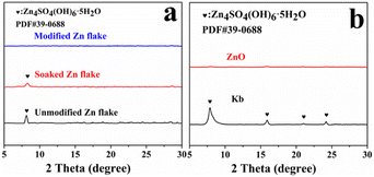 | ||
| Fig. 10 (a) XRD patterns of immersed zinc flakes, unmodified and modified zinc flakes after cycling. (b) XRD patterns of zinc flakes after cycling with ZnO and KB modification alone. | ||
To study the real-life application of the modified separator, Zn//MnO2 were assembled with unmodified (bare Zn//MnO2) and modified separators (modified Zn//MnO2). The Nyquist plots, CV curves and cycling performance of bare and modified Zn//MnO2 were shown in Fig. 11. According to the EIS results, the Re and Rct of modified Zn//MnO2 decreased, and the smaller Rct exhibited faster charge transfer. After fitting, Re and Rct of modified Zn//MnO2 were 0.468 and 2.577 Ω, bare Zn//MnO2 were 1.15 and 96 Ω (Table S1†), it caused by the highly conductive network of KB. Meanwhile, the higher slope in the low frequency region indicated faster ion diffusion of modified Zn//MnO2.27 The CV curves of bare and modified Zn//MnO2 showed in Fig. 11(b), the two pairs of redox peaks correspond to the stepwise conversion of Mn4+/Mn3+ and Mn3+/Mn2+, the modified oxidation peak shifts to the left, indicating the minor polarization.27 The cycle life of bare and modified Zn//MnO2 was shown in Fig. 11(c). The modified Zn//MnO2 cycled 995 times stably, and bare Zn//MnO2 only cycled 203 times. The failure of the battery was mainly due to the short circuit caused by dendrites pierced the separator. The capacity fading in this system occurred at the beginning of the battery cycle,32 the modified Zn//MnO2 would be cycled stably after capacity fading, and the coulombic efficiency was stable at 99.5%, showing the excellent electrochemical performance. It is known that the cells generated dendrites resulted from the uneven deposition of zinc ions on the surface of the anode electrode,13 as shown in Fig. 1. However, after co-modified with ZnO and KB, zinc-ions were deposited on ZnO preferentially as the deposition point of the modified layer rather than on the zinc cathode directly. With the plating/stripping of Zn2+, the ZnO in the KB network refined gradually, which increased the deposition sites of Zn2+. The 3D KB network could also withstand the deformation caused by Zn2+ plating/stripping, it consequently reduced the formation of dendrites. After the modification of the separator, only a small amount of Zn was deposited on the Zn anode directly. And the modified Zn//MnO2 cycled stably for 995 times. Therefore, it can be concluded that KB and ZnO improved the environment of zinc deposition synergistically, suppressed dendrites, and improved the electrochemical performance of the Zn//MnO2.
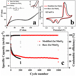 | ||
| Fig. 11 (a) CV curves of bare and modified Zn//MnO2 at 0.5 mV s−1; (b) Nyquist plots of bare and modified Zn//MnO2; (c) long-term cycling performance of bare and modified Zn//MnO2. | ||
4. Conclusion
In this paper, ZnO and KB were mixed homogeneously by sonication and sprayed on commercial glass fiber separators for Zn dendrite suppression. The 3D KB network with high conductivity can reduce the cell impedance and improve the ion transfer. And ZnO has a stronger adsorption for zinc atom than Zn, zinc therefore was deposited on ZnO preferentially. The deposited particles was refined while reduced the side reaction products. The modified symmetric cell can cycle stably for 2218 thanks to the synergistic effect of KB and ZnO. The zinc anode formed a net-like zinc deposition after cycling, which suppressed the generation of dendrites. The modified Zn//MnO2 exhibited excellent cycle performance as well and cycled 995 times. The obtained results indicate that the modification strategy for the separators was effective to reduce the by-product generation and inhibit the production of dendrites in zinc symmetric cells. The electrochemical performance of the cells was greatly improved after modification.Conflicts of interest
There are no conflicts to declare.Acknowledgements
This work was financially supported by National Key R&D Program of China (2021YFB4001502), National Natural Science Foundation of China (No. 21875056 and No. 22075231), and the Sichuan Science and Technology Program (No. 2020YFSY0026 and No. 2021YFSY0022). The authors also appreciate the financial support by special project for the Central Government to Guide the Development of Local Science and Technology in Sichuan Province (2021ZYD0099).References
- W. C. Du, E. H. X. Ang, Y. Yang, Y. F. Zhang, M. H. Ye and C. C. Li, Energy Environ. Sci., 2020, 13, 3330–3360 RSC.
- M. Li, Z. L. Li, X. P. Wang, J. S. Meng, X. Liu, B. K. Wu, C. H. Han and L. Q. Mai, Energy Environ. Sci., 2021, 14, 3796–3839 RSC.
- B. Y. Tang, L. T. Shan, S. Q. Liang and J. Zhou, Energy Environ. Sci., 2019, 12, 3288–3304 RSC.
- T. S. Zhang, Y. Tang, S. Guo, X. X. Cao, A. Q. Pan, G. Z. Fang, J. Zhou and S. Q. Liang, Energy Environ. Sci., 2020, 13, 4625–4665 RSC.
- X. Zeng, K. Xie, S. Liu, S. Zhang, J. Hao, J. Liu, W. K. Pang, J. Liu, P. Rao and Q. Wang, Energy Environ. Sci., 2021, 14, 5947–5957 RSC.
- C. J. Xu, B. H. Li, H. D. Du and F. Y. Kang, Angew. Chem., Int. Ed., 2012, 51, 933–935 CrossRef CAS PubMed.
- D. Yuan, J. Zhao, H. Ren, Y. Q. Chen, R. Chua, E. T. J. Jie, Y. Cai, E. Edison, W. Manalastas, M. W. Wong and M. Srinivasan, Angew. Chem., Int. Ed., 2021, 60, 7213–7219 CrossRef CAS PubMed.
- J. N. Hao, L. B. Yuan, C. Ye, D. L. Chao, K. Davey, Z. P. Guo and S. Z. Qiao, Angew. Chem., Int. Ed., 2021, 60, 7366–7375 CrossRef CAS PubMed.
- M. Zhou, Y. Chen, G. Fang and S. Liang, Energy Storage Mater., 2022, 45, 618–646 CrossRef.
- Y. Li, Z. H. Wang, Y. Cai, M. E. Pam, Y. K. Yang, D. H. Zhang, Y. Wang and S. Z. Huang, Energy Environ. Mater., 2022, 1–29 Search PubMed.
- B. Li, X. Zhang, T. Wang, Z. He, B. Lu, S. Liang and J. Zhou, Nano-Micro Lett., 2021, 14, 121–151 Search PubMed.
- R. Yuksel, O. Buyukcakir, W. K. Seong and R. S. Ruoff, Adv. Energy Mater., 2020, 10, 1904215 CrossRef CAS.
- Q. Yang, G. J. Bang, Y. Guo, Z. X. Liu, B. X. Yon, D. H. Wang, Z. D. Huang, X. L. Li, J. Fan and C. Y. Zhi, Adv. Mater., 2019, 31, 1903778 CrossRef CAS PubMed.
- A. L. Xia, X. M. Pu, Y. Y. Tao, H. M. Liu and Y. G. Wang, Appl. Surf. Sci., 2019, 481, 852–859 CrossRef CAS.
- F. Wang, O. Borodin, T. Gao, X. L. Fan, W. Sun, F. D. Han, A. Faraone, J. A. Dura, K. Xu and C. S. Wang, Nat. Mater., 2018, 17, 543–549 CrossRef CAS PubMed.
- C. Zhang, J. Holoubek, X. Wu, A. Daniyar, L. Zhu, C. Chen, D. P. Leonard, I. A. Rodriguez-Perez, J. X. Jiang, C. Fang and X. Ji, Chem. Commun., 2018, 54, 14097–14099 RSC.
- Y. X. Zeng, X. Y. Zhang, R. F. Qin, X. Q. Liu, P. P. Fang, D. Z. Zheng, Y. X. Tong and X. H. Lu, Adv. Mater., 2019, 31, 1903675 CrossRef PubMed.
- Z. M. Zhao, J. W. Zhao, Z. L. Hu, J. D. Li, J. J. Li, Y. J. Zhang, C. Wang and G. L. Cui, Energy Environ. Sci., 2019, 12, 1938–1949 RSC.
- W. N. Xu, K. N. Zhao, W. C. Huo, Y. Z. Wang, G. Yao, X. Gu, H. W. Cheng, L. Q. Mai, C. G. Hu and X. D. Wang, Nano Energy, 2019, 62, 275–281 CrossRef CAS.
- S. B. Wang, Q. Ran, R. Q. Yao, H. Shi, Z. Wen, M. Zhao, X. Y. Lang and Q. Jiang, Nat. Commun., 2020, 11, 1634 CrossRef PubMed.
- J. X. Zheng, Q. Zhao, T. Tang, J. F. Yin, C. D. Quilty, G. D. Renderos, X. T. Liu, Y. Deng, L. Wang, D. C. Bock, C. Jaye, D. H. Zhang, E. S. Takeuchi, K. J. Takeuchi, A. C. Marschilok and L. A. Archer, Science, 2019, 366, 645–648 CrossRef CAS PubMed.
- C. Li, Z. Sun, T. Yang, L. Yu, N. Wei, Z. Tian, J. Cai, J. Lv, Y. Shao, M. H. Rummeli, J. Sun and Z. Liu, Adv. Mater., 2020, 32, e2003425 CrossRef PubMed.
- Y. W. Su, B. Z. Liu, Q. H. Zhang, J. Peng, C. H. Wei, S. Li, W. P. Li, Z. K. Xue, X. Z. Yang and J. Y. Sun, Adv. Funct. Mater., 2022, 32, 2204306 CrossRef CAS.
- Y. Teng, M. Mo, Y. Li, J. Xue and H. Zhao, J. Alloys Compd., 2018, 744, 712–720 CrossRef CAS.
- X. S. Xie, S. Q. Liang, J. W. Gao, S. Guo, J. B. Guo, C. Wang, G. Y. Xu, X. W. Wu, G. Chen and J. Zhou, Energy Environ. Sci., 2020, 13, 503–510 RSC.
- Z. Z. Yuan, X. Q. Liu, W. B. Xu, Y. Q. Duan, H. M. Zhang and X. F. Li, Nat. Commun., 2018, 9, 1–11 CrossRef CAS PubMed.
- R. Guo, X. Liu, F. Xia, Y. Jiang, H. Zhang, M. Huang, C. Niu, J. Wu, Y. Zhao, X. Wang, C. Han and L. Mai, Adv. Mater., 2022, 34, e2202188 CrossRef PubMed.
- L. Tan, C. Wei, Y. Zhang, Y. An, S. Xiong and J. Feng, Chem. Eng. J., 2022, 431, 134277 CrossRef CAS.
- Z. G. Hou, X. Q. Zhang, X. N. Li, Y. C. Zhu, J. W. Liang and Y. T. Qian, J. Mater. Chem. A, 2017, 5, 730–738 RSC.
- Q. P. Jian, Y. H. Wan, J. Sun, M. C. Wu and T. S. Zhao, J. Mater. Chem. A, 2020, 8, 20175–20184 RSC.
- L. Ma, M. A. Schroeder, O. Borodin, T. P. Pollard, M. S. Ding, C. S. Wang and K. Xu, Nat. Energy, 2020, 5, 743–749 CrossRef CAS.
- N. Zhang, F. Cheng, J. Liu, L. Wang, X. Long, X. Liu, F. Li and J. Chen, Nat. Commun., 2017, 8, 405 CrossRef PubMed.
Footnote |
| † Electronic supplementary information (ESI) available. See DOI: https://doi.org/10.1039/d2ra07745k |
| This journal is © The Royal Society of Chemistry 2023 |

