 Open Access Article
Novel sustainable magnetic material to improve the wireless charging of a lightweight drone
Alicia Triviño *a,
Inmaculada Casaucao
 a,
Juan Carlos Quirósa,
Paula Pérez
 b and
Antonio Rojasb
aDepartment of Electrical Engineering, University of Malaga, Malaga, 29071, Spain. E-mail: atc@uma.es; icct@uma.es; quirosgil76@uma.es
bPREMO GROUP, Malaga, 29590, Spain. E-mail: paula.perez@grupopremo.com; antonio.rojas@grupopremo.com
First published on 4th April 2023
Abstract
Unmanned aerial vehicles are clear candidates to benefit from wireless power transfer, as it can facilitate their charging process and even allow them to charge autonomously. One common approach when designing a wireless power transfer (WPT) system is to incorporate ferromagnetic material to guide the magnetic field and improve system efficiency. However, a complex optimization calculation must be carried out to determine the positions and size of the ferromagnetic material and thereby restrict the additional weight imposed. This is severely limiting in the case of lightweight drones. To alleviate this burden, we show the feasibility of incorporating a novel sustainable magnetic material, called MagPlast 36-33, which has two main features. First, it is lighter than ferrite tiles and can therefore be used without having to consider complex geometries to reduce the weight. In addition, its manufacturing process is based on the principle of sustainability, since it is produced from recycled ferrite scrap generated in the industry. Its physical characteristics and properties mean that it can be used to improve the efficiency of the wireless charger, adding a weight lower than that of conventional ferrites. The experimental results we obtained in the laboratory demonstrate the feasibility of using this type of recycled material in lightweight drones operating at the frequency imposed by SAE J-2954. Furthermore, we have conducted a comparative analysis with a different ferromagnetic material commonly used in WPT systems, in order to verify the benefits of our proposal.
Drones have become a helpful tool for many organisations in multiple purposes, as they can replace humans in the execution of risky tasks. With the advancement of wireless charging in electronic devices, the possibility of designing wireless chargers for drones is being considered to increase their autonomy. In this way, they could be used even in adverse conditions, without the need to be in direct contact with an operator to start the charging process. However, new technologies incorporated to the drones must guarantee their operativity and aerodynamics, which are limited by weight, size, position and dimensions of the added components. Thus, in order to introduce the wireless charging infrastructure in a drone, the number of components used and the weight of these components must be reduced as much as possible. In an inductive wireless charger, numerous components are used, such as power converters, compensation systems and coils, through which the power will be transmitted. In some cases, ferromagnetic material is used to improve power transmission and increase charging efficiency. This paper proposes the design of an inductive wireless charger, using a novel ferromagnetic material. This ferromagnetic material is composed of recycled ferrite scraps and silicon, so that its density is lower than that of conventional ferrite. This reduces the weight and costs of the added infrastructure, which is a crucial part in the case of drones.
1 Introduction
Unmanned Aerial Vehicles (UAV) are popular devices that help to execute monitoring and surveillance tasks in military, industrial and commercial applications. As presented in ref. 1, one of the most significant drawbacks of these vehicles is their poor autonomy (around 15–30 minutes) because of the compromise between the battery capacity and its weight. Thus, it is necessary to develop advanced mechanisms that enable a reliable and efficient charge for UAVs. For this reason, UAVs or drones can clearly benefit from wireless chargers to be able to operate and charge autonomously even in adverse conditions.Wireless Power Transfer (WPT) comprises a set of technologies for near-field, mid-range and far-field. The convenience of each technology mainly depends on the distance between the transmitter and the receiver (referred to as gap) and the power requirements.2 Specifically, in drones, the charge to drones flying at an elevated height (around 1 km) may be performed by means of laser power beaming, but an inductive charger3 is preferred for drones flying closer. When applied to the transport sector, this technology is based on two air-coupled coils (one in the transmitter and another in the receiver) operating with a kHz-current.4 As can be observed in Fig. 1, power converters are included in both the primary (power transmitter) and the secondary (power receiver) sides in order to work in this frequency range. The most simple configurations opt for a DC source (obtained from a rectifier) and an inverter on the primary side. The power converter on the secondary side is a rectifier. Compensation networks are also incorporated to make the system work at resonance and thereby achieve greater efficiency.
UAVs in particular impose several requirements on their wireless chargers. These are stricter than in car applications, and include weight and aerodynamics, which must be carefully considered for the coils and the electronics on the secondary side. These conditions require a tailored design process for UAVs. Several experimental works have been conducted to analyse and develop wireless chargers for UAVs. Focusing on the geometry of the secondary coil, the authors in ref. 5 design a fixed structure for the power transmitter into which the secondary coil must be inserted in order to have a fully aligned power transfer. Although the efficiency is improved, forcing the position may restrict its usability. A similar limitation can be found in,6 where the authors present a parallelepiped structure with ferrite coils for the power transmitter. An outer aluminium ring is proposed as a secondary coil in.7 This coil is lighter than a Litz-wire coil but it has to extend the vehicle's dimensions, which may not be suitable for all applications. In order to ease the charging process, the authors in ref. 8 analyse a power transmitter composed of multiple coils, activating only the one closest to the power transmission. The receiving coil in the drone is placed in its landing legs with a rectangular geometry. It works at 150 kHz and 64 W. A different frequency is selected in,9 where a 50 kHz drone is implemented with an output power equal to 500 W. The weight of the secondary structure is 130 g. The authors use a receiving coil on the drone legs, which are perpendicular to the transmitter coil. In ref. 10, the authors design a rectangular coil extending all the drone's basis for the power receiver. The operation frequency is 370 kHz.
It can be observed that the previous works do not use the operational frequency recommended by SAE J-2954.11 According to this standard, the frequency should be in the interval between 79 and 90 kHz, so the charger should be operated within this range. In our design, the working frequency is 85 kHz in order to be compliant with this standard. The frequency of the excitation affects the magnetic field, the related electromagnetic emissions and the convenience of using ferromagnetic materials.12 The conventional ferromagnetic material improves the power transfer of the system and is of great utility for this type of application. However, incorporating ferrites brings disadvantages that cannot be ignored, such as the extra weight it adds to the system. For this reason, a large amount of research is focused on optimizing the amount of material included in the structure to achieve a decrease in weight.13 Nevertheless, to avoid laborious optimization calculations during the system design phase, other lighter magnetic materials can be used. The work in ref. 14 analyses the use of a flexible magnetic material for the receiving coils. It is wound in the drone landing legs forming a combined solenoid. The need for magnetic material is not studied here, though it has been seen to improve the efficiency of the power transmission.
In this paper, we focus on designing and manufacturing a new magnetic material. The main objective is to achieve a material that is lighter than conventional ferrites so that it can be used in lightweight power receivers. Reducing weight is one priority in sustainable transport.15 One of our priorities in the design and manufacturing process has been the use of recycled materials from a manufacturing company's production scrap. There is thus no need to acquire new ferromagnetic materials; instead we exploit the surplus or residues available from other production processes. This strategy supports the principle of sustainability in the manufacturing of new materials. In this work, we analyse the suitability of using this novel sustainable lightweight ferrite-based material in a wireless charger for a drone. This material provides good electromagnetic properties for the drone structure, achieving greater efficiency without significantly increasing the weight of the system. In general, special ferromagnetic material has been used in WPT applications such as electric vehicles16 or implantable devices,17 but not in drones and without prioritizing the sustainability of the material during the manufacturing process.
In our implementation of a wireless charger for drones, we demonstrate the improvements that this recycled material brings to the system in terms of power and efficiency. Although we have opted for circular coils, we believe that the conclusions are valid for other geometries. The use of other coil geometries may be imposed by the application requirements (position of cameras, sensors, etc).
The remainder of the paper is structured as follows. Section II gives a description of the magnetic material used for the system design. Section III details the design process of the charger in which the magnetic material will be tested. Section IV presents the evaluation of the wireless charger implemented in the laboratory as well as a comparative analysis with a different ferromagnetic material. Finally, Section V outlines the main conclusions and future work.
2 Sustainable and light magnetic material
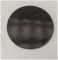
In the design proposed for the wireless charger of a drone, we have built and used a novel material called MagPlast 36-33. Its appearance can be seen in Fig. 2. Due to its reduced thickness (3 mm), this material can easily be incorporated into the bottom surface of any of the wireless charger's coils.MagPlast 36-33 is a Polydimethylsiloxane (PDMS)-based elastomeric compound of a two-component encapsulating system with 80–85% ferrite, 0.9 W mK−1 and 1.6 kV mm−1. PDMS, also known as dimethicone, is the linear polymer of dimethylsiloxane. It belongs to the group of organosilicon compounds, substances commonly known as silicones. PDMS is the most widely used silicon-based organic polymer and is particularly known for its unusual rheological properties. Polydimethylsiloxane is transparent and generally inert, harmless and non-flammable.
This material can be considered a sustainable composite, as it is manufactured from scrap generated by the company itself. Specifically, recycled MnZn ferrite is used as raw material to manufacture the composite. To convert scrap into raw material, ferritic material (MnZn ferrite) from end-of-life electronic devices is used to give it a second life and contribute to the reduction of global CO2 emissions.
In order to use this scrap as raw material for this composite, the recycled ferrite is first crushed, as shown in Fig. 3(a), and then a planetary ball mill grinds it to a particle size distribution of less than 200 microns, as seen in Fig. 3(b).
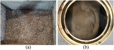 | ||
| Fig. 3 (a) Ferrite scrap generated by the industry after preliminary rough grinding. (b) Ground ferrite. | ||
During its manufacturing process, there are two different components (component A as resin and component B as hardener) which contain two different compounds of PDMS, mixed with the MnZn ferrite particles derived from the grinding process. Components A and B are prepared separately and then mixed together in a 1![[thin space (1/6-em)]](https://www.rsc.org/images/entities/char_2009.gif) :
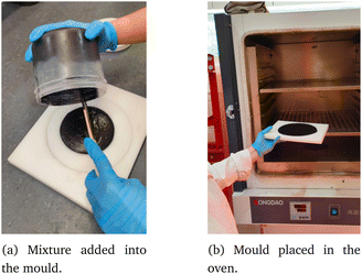
:![[thin space (1/6-em)]](https://www.rsc.org/images/entities/char_2009.gif) 1 ratio by weight in a mixer known as Speedmixer, which allows homogeneous mixtures with high filler concentrations to be obtained. The load percentage of ferromagnetic material (sintered ferrite powder, MnZn with μ i >3000) is 80–85% in both components A and B. Once the mixing process is completed, it is poured into the mould where the cross-linking process begins (Pot-Life is 20–25 minutes at 25 °C). The mould containing the material is placed in the oven at 90 °C for 40 minutes to cure the material and thus accelerate the cross-linking process, as illustrated in Fig. 4. Once cured, the sustainable magnetic material acquires properties suitable for improving the wireless charging of a lightweight drone.
1 ratio by weight in a mixer known as Speedmixer, which allows homogeneous mixtures with high filler concentrations to be obtained. The load percentage of ferromagnetic material (sintered ferrite powder, MnZn with μ i >3000) is 80–85% in both components A and B. Once the mixing process is completed, it is poured into the mould where the cross-linking process begins (Pot-Life is 20–25 minutes at 25 °C). The mould containing the material is placed in the oven at 90 °C for 40 minutes to cure the material and thus accelerate the cross-linking process, as illustrated in Fig. 4. Once cured, the sustainable magnetic material acquires properties suitable for improving the wireless charging of a lightweight drone.
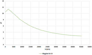
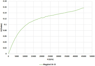
We obtained the magnetic relative permeability and B–H curves of the material generated, as shown in Fig. 5 and 6, respectively. The magnetic permeability (μ) of the material can be calculated from the B–H curve so that the relative permeability (μr) is:
 | (1) |
We can observe that the material's relative permeability is not constant, since it depends on H. In case of saturable materials, μ reaches a maximum value and then decreases as its value approaches the saturation state. The maximum relative magnetic permeability is 11, which is reached at a value of 2000 A m−1. From 6, it can be deduced that as the H field increases, the B field asymptotically approaches a maximum value, called the saturation value. Once the material is at saturation point, the B field continues to increase at the paramagnetic rate. For Magplast 36-33, magnetic saturation takes place at 110 mT approximately. Although the charging process can be autonomous, other people may be in the nearby area, so we consider it appropriate to establish the requirement to comply with current regulations. It should be noted that ICNRP18 limits the magnetic field of devices to 6.25 μT for a variation in the system's working frequency from 3 kHz to 150 kHz, so the material is not expected to be saturated in commercial wireless chargers.
Because of its characteristics, listed in Table 1, MagPlast 36-33 is an ideal material for wireless chargers with restrictions on weight. It is flexible, easy to position and, above all, it has a reduced weight as it presents low density compared to ferrite magnets (2.9 g cm−3 over 4.9–5.1 g cm−319). As shown in Table 2, the permeability of this material has a low variation with the frequency, being almost constant for the operational range considered by SAE J-2954.
| Property | Value | Unit |
|---|---|---|
| Initial permeability, μi | 11 | — |
| Magnetic saturation | 115 | mT |
| Density | 2.9 ± 0.1 | g cm−3 |
| Flammability test UL 94 V | V0 | — |
| Thermal conductivity | 0.90–0.99 | W mK−1 |
| Hardness, shore D | 4–5 | — |
| Diffusivity | 4.70 × 10⁻⁷ | m2 s−1 |
| Dielectric strength | 1.6 | kV mm−1 |
| Freq. (kHz) | 0.05 | 0.1 | 0.5 | 1 | 5 | 10 | 50 | 100 | 500 | 1000 |
| μi | 7.82 | 7.83 | 7.84 | 7.83 | 7.84 | 7.84 | 7.81 | 7.82 | 7.76 | 7.79 |
In particular, MagPlast 36-33 has a very important advantage over other polymer bonding magnetic materials (PBM), considering its application for drones. In the literature, there are some solutions in which a polymer-based composite, such as the one proposed in,20 is used as ferromagnetic material. In that case, the amount of ferrite included in the composite ranges from 50 to 60%. However, in contrast, the ferrite we designed has 80–85% ferrite, which helps the concentration of the magnetic field in the area between the primary and the secondary coils. On the other hand, when we analyse the material's density, we find that our material has a density of approximately 2.9 g cm−3 compared to around 5.8 g cm−3 in the aforementioned paper. Thus, for the same volume, our material has a lower weight, which is a significant advantage for the WPT charger of a drone, where weight is a constraint.
3 Design and implementation of the UAV wireless charger
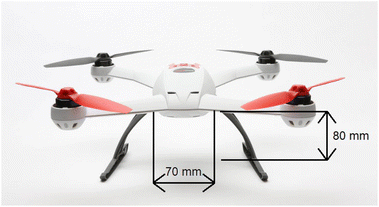
To test the material's suitability, we designed and implemented a wireless charger for a lightweight drone. For our application, this charger is intended for the Blade 350 QX quadcopter drone, which is shown in Fig. 7. The drone works with a 2200 mA h Li–Po, which is charged up to 50 W. It has a discharge capacity of 40–80 C and a charging capacity of 8 C. The working voltage is 11.1 V but higher voltages can be used if they do not exceed 12.6 V. Under normal conditions, it has a relatively short autonomy of approximately 15 minutes, like most commercial drones. The drone's dimensions limit the space available to position the coils.When designing the charger, we prioritized reduced dimensions, low weight and low cost on the secondary side to ease its incorporation, as recommended in ref. 21.
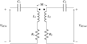
For the coils, we opted for a circular geometry, as it is more suitable for lightweight structures.22 In addition, the coils will be connected in a Series–Series (SS) configuration with the compensation networks since this topology facilitates the control algorithm.23 It also has a better performance with variations on the system parameters, i.e. with mutual inductance and load variations.24 Fig. 8 shows the equivalent circuit for the core of the wireless charger.
Where V1AC is the inverter AC output voltage and V2AC is the rectifier AC input. The correct values of the capacitors C1 and C2 depend on the inductances of the coil. Specifically:
 | (2) |
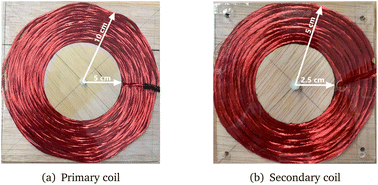
With an iterative algorithm such as the one described in,8,9 we determined the optimal dimensions and number of turns of the coils. The algorithm searches for a solution with a minimum weight on the secondary side, as this is one of the requirements imposed on this application. Based on this result, we built the coils shown in Fig. 9.
Taking into account the power managed by the application, a half-bridge square-wave inverter is used. It is composed of two n-type IRFZ44NPbF MOSFET. The driver that controls the transistors is the IRS2153, which sends a square wave signal to drive the transistors at constant frequency. For the rectifier, we used four Schottky 80SQ045N diodes, which are suitable for working with high frequencies, such as those set by SAE J2954.
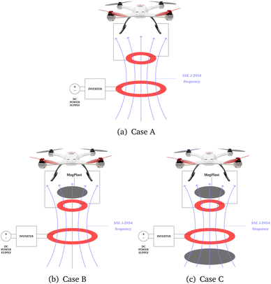
Once we had defined the coil dimensions, we designed and manufactured the PDMS material accordingly. As a first option, the material was inserted on the secondary side, as illustrated in Fig. 10(b). The secondary side is more affected by the weight restrictions, so it is more important to position the novel magnetic material on this side. However, we also studied the behaviour of the system when the ferromagnetic material was inserted on both the primary and secondary sides, as shown in Fig. 10(c). The physical characteristics and dimensions of MagPlast 36-33 are shown in Table 3 for the primary and secondary sides. It should be noted that the PDMS and the coils are in contact but they are depicted separately in Fig. 10 to illustrate the components clearly. The separation between the primary and the secondary coils is 30 mm.
| Parameter | Value | |
|---|---|---|
| Primary side | Geometry | Circular |
| Diameter | 150 mm | |
| Weight | 131.47 g | |
| Secondary side | Geometry | Square |
| Dimensions | 100 mm × 100 mm | |
| Weight | 84.75 g |
4 Experimental validation
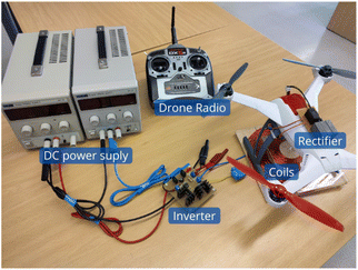
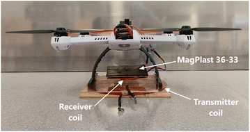
To evaluate the performance of the drone wireless charger we designed, the prototype was fully built and tested as illustrated in Fig. 11. We carried out three different experiments with the prototype: one without the ferromagnetic material (Case A), another with the ferromagnetic material on the secondary side (Case B), and a final experiment with the ferromagnetic material on both sides (Case C). The position of Magplast 36-33 can be seen in Fig. 12. For each of these cases, we studied the system performance for a DC output voltage of 10 V, whose output power is 32 W. Performing the same experiment with the same output conditions for each case therefore made it easier to subsequently compare the results.First, we ensured that the magnetic field generated by the WPT drone charger was lower than the magnetic field saturation value of MagPlast 36-33. To do so, measurements were taken on three axes, resulting in 170 nT on XY axis, 275 nT in ZY axis and 440 nT in ZY axis. When these results are compared, we can verify that the magnetic field generated is lower than the ferromagnetic material saturation value.
Moreover, it should be noted that when the ferromagnetic material is added, the coil self-inductance improves.25 In Table 4, the real values of the primary and secondary coils are shown for the three coil configurations we tested. The features of the coils are measured with LCR HM8118. For each inductance value, a resonant capacitor was calculated for a 85 kHz resonant frequency (eqn (2)), according to SAE J-2954.
| Parameter | Value |
|---|---|
| L1A | 105.50 μH |
| L2A | 10.44 μH |
| C1A | 32.23 nF |
| C2A | 335.65 nF |
| L1B | 104.22 μH |
| L2B | 12.92 μH |
| C1B | 33.00 nF |
| C2B | 271.33 nF |
| L1C | 113.10 μH |
| L2C | 13.03 μH |
| C1C | 30.99 nF |
| C2C | 269.02 nF |
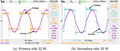
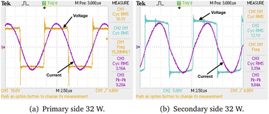
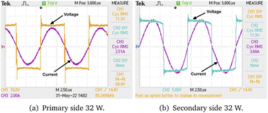
In each case, the measurements were taken at different electrical points of the prototype to determine the voltage and current values (and efficiency) both in alternating and direct current (AC and DC respectively). At the inverter input and rectifier output, the values were obtained in direct current, while at the inverter output and rectifier input, the values were obtained in alternating current. The measured values are summarized in Tables 5 and 6. The screenshots are in Fig. 13–15 for cases A, B and C respectively.
| Case A | Case B | Case C | |
|---|---|---|---|
| VDCin [V] | 16.95 | 18.58 | 20.90 |
| IDCin [A] | 2.73 | 2.39 | 2.03 |
| VACin [V] | 16.8 | 18.2 | 20.8 |
| IACin [A] | 4.88 | 4.48 | 3.28 |
| Phase shift [ns] | 20 | 15 | 920 |
| Case A | Case B | Case C | |
|---|---|---|---|
| VACout [V] | 12 | 12.4 | 11.8 |
| IACout [A] | 4.88 | 4.9 | 5.28 |
| VDCout [V] | 10 | 10 | 10 |
| IDCout [A] | 3.2 | 3.2 | 3.2 |
| Phase shift [ns] | 20 | 12 | 0 |
Based on all the results obtained, it can be determined that when the ferromagnetic material is introduced, a higher inverter input DC voltage is required to achieve the same power as the system output. The effect observed in the current is the opposite, as output power decreases in value when ferromagnetic material is included. It should be noted that, in terms of the voltage and current received in the rectifier (VACout and IACout respectively), there are no significant variations between including or not including ferromagnetic material.
In terms of efficiency, after analysing the results of Table 7, we can draw a number of conclusions. First, it can be seen that the addition of the ferromagnetic material increases efficiency for both direct current and alternating current. Another detail extracted from the analysis of the results is that the improvement in efficiency in alternating current is greater than the improvement in efficiency in direct current: better results are observed in AC (19.91%) than in DC (improvements of up to 6.37%). The new magnetic material increases the quality factors of the coils and the coupling coefficient between them so that the efficiency of the system is improved. In addition, it can be observed that when ferromagnetic material is included on both sides of the circuit there is a greater increase in efficiency than when the material is placed only on the secondary side. It should be noted that when ferrite is included on both sides, the power demand on the grid to charge the drone is reduced, thus leading to a more efficient use of energy.
| Case A | Case B | Case C | |
|---|---|---|---|
| AC eff. [%] | 71.42 | 74.52 | 91.33 |
| DC eff. [%] | 69.05 | 71.95 | 75.42 |
4.1 Comparative analysis with different material
In this subsection we have carried out a comparative analysis of three different cases which will be detailed bellow. In order to compare the performance of our proposal, we have repeated the experimental test with a different ferromagnetic material. This ferromagnetic material, which is commonly used in WPT systems, has a density of 5.2 g cm−3, which is considerably higher than MagPlast 36-33 density (2.9 g cm−3).With this consideration, two additional experiments have been carried out. First, we propose the case of a ferromagnetic material with similar weight (SW). We consider it appropriate to conduct experiments using common ferrite plates with a weight equivalent to MagPlast 36-33, which is approximately 80 g. The configuration used for these plates is radial, as this is the optimal configuration according to the literature.26 Additionally, we have performed a different case based on the selection of a similar area (SA). In order to evaluate a different parameter, an experiment has been carried out with common ferrite in which the occupied area is equivalent to the MagPlast area, which is approximately 100 cm2.
Tables 8 and 9 show the results obtained for the comparative analysis. It can be observed that, for the Ferrite SW configuration, the AC efficiency of the system increases. Another effect of this configuration is the rise of the current in the primary side, which makes the system work with less input DC voltage. This increase in current leads to increased losses in semiconductors and conductors. As as consequence, the DC efficiency is reduced making this configuration a worse option than MagPlast 36-33. Ferrite SA configuration shows a similar behaviour than SW configuration. The AC efficiency of the system is increased due to the higher coupling coefficient reached. This configuration also makes the current in the primary side to be higher and thus, the losses in semiconductors and conductors rise. In conclusion, it can be seen that in a comparative analysis with other option of materials, MagPlast 36-33 can maintain a higher efficiency while reducing the weight in the secondary coil.
| Ferrite SW | Ferrite SA | Proposal | |
|---|---|---|---|
| VDCin [V] | 11.09 | 11.39 | 18.58 |
| IDCin [A] | 4.64 | 4.76 | 2.73 |
| VACin [V] | 10.6 | 10.8 | 18.2 |
| IACin [A] | 7.68 | 8.32 | 4.48 |
| VACout [V] | 13.6 | 14 | 12.4 |
| IACout [A] | 4.96 | 4.88 | 4.9 |
| VDCout [V] | 12.3 | 12.3 | 10 |
| IDCout [A] | 2.6 | 2.6 | 3.2 |
| Ferrite SW | Ferrite SA | Proposal | |
|---|---|---|---|
| AC eff. [%] | 82.86 | 76.03 | 74.52 |
| DC eff. [%] | 62.10 | 58.98 | 71.95 |
| Weight [g] | 80.40 | 160.72 | 84.75 |
| Density [g cm−3] | 5.20 | 5.20 | 2.90 |
| Area | 47.5 cm2 | 95 cm2 | 100 cm2 |
5 Conclusions
In this paper we present the design and fabrication of a sustainable ferromagnetic material built of recycled industrial materials. MnZn scraps were used to produce the material; these were ground and then mixed with a Polydimethylsiloxane substrate. After a curing process, we obtained a flexible ferrite of lighter weight than conventional ferrites. The resulting material is lightweight, compact and flexible, which are required features for some wireless power transfer applications. Specifically, we incorporated the material into the design and implementation process for a lightweight drone wireless charger. When the novel ferromagnetic material – MagPlast 36-33 – was inserted, we observed an increase in the quality factor, coupling, and AC and DC efficiency. Thus, the charge is improved with this sustainable material without incurring a significant added load for the drone. In addition, after a comparison with another type of ferromagnetic material with an equivalent configuration in weight, and another equivalent configuration in area, it has been demonstrated that the DC efficiency is higher in our proposal.Conflicts of interest
There are no conflicts to declare.References
- M. Lu, M. Bagheri, A. P. James and T. Phung, IEEE Access, 2018, 6, 29865–29884 Search PubMed.
- S. Barman, A. Rez, N. Kumara and K. BakarMunir, Renewable Sustainable Energy Rev., 2015, 51, 1525–1552 CrossRef.
- A. Triviño, J. M. González-González and J. A. Aguado, Energies, 2021, 14, 1547 CrossRef.
- Y. Guo, H. Zhang, H. Liu, S. Li, S. Yin, P. Cao, L. Zhang, X. Ping and L. Guo, RSC Adv., 2020, 10, 35426–35432 RSC.
- S. Obayashi, Y. Kanekiyo, K. Nishizawa and H. Kusada, 2019 IEEE Wireless Power Transfer Conference, WPTC 2019, 2019, pp. 80–84 Search PubMed.
- S. Wu, C. Cai, L. Jiang, J. Li and S. Yang, IEEE Trans. Power Electron., 2020, 7564–7575 Search PubMed.
- T. Campi, S. Cruciani, F. Maradei and M. Feliziani, 2019 Joint International Symposium on Electromagnetic Compatibility, Sapporo and Asia-Pacific International Symposium on Electromagnetic Compatibility, EMC Sapporo/APEMC 2019, 2019, pp. 601–604 Search PubMed.
- T. Campi, S. Cruciani and M. Feliziani, Energies, 2018, 11, 352 CrossRef.
- C. Cai, J. Liu, S. Wu, Y. Zhang, L. Jiang, Z. Zhang and J. Yu, IEEE Access, 2020, 8, 67974–67989 Search PubMed.
- D. Ke, C. Liu, C. Jiang and F. Zhao, IECON 2017 – 43rd Annual Conference of the IEEE Industrial Electronics Society, 2017, pp. 6949–6954 Search PubMed.
- SAE International, J2954B: Wireless power transfer for light-duty plug-in/electric vehicles and alignment methodology, 2020 Search PubMed.
- A. Triviño-Cabrera, J. Aguado and J. González, Electron. Lett., 2017, 53, 871–873 CrossRef.
- Z. Dai, J. Wang, M. Long, H. Huang and M. Sun, AIP Adv., 2017, 7, 095013 CrossRef.
- Z. Bie, J. Zhang, K. Song, D. Wang and C. Zhu, IEEE Trans. Ind. Electron., 2022, 69, 10154–10161 Search PubMed.
- M. Akhshik, A. Bilton, J. Tjong, C. V. Singh, O. Faruk and M. Sain, Sustainable Mater. Technol., 2022, 31, e00370 CrossRef CAS.
- T. Campi, S. Cruciani, V. D. Santis, F. Maradei and M. Feliziani, Wirel. Power Transf., 2018, 5, 1–8 CrossRef.
- Y. Zhou, C. Liu and Y. Huang, Energies, 2020, 13, 2837 CrossRef.
- International Commission on Non-Ionizing Radiation Protection (ICNIRP), Health Phys., 2010, 99, 818–836 CrossRef PubMed.
- S. Kontos, A. Ibrayeva, J. Leijon, G. Mörée, A. E. Frost, L. Schönström, K. Gunnarsson, P. Svedlindh, M. Leijon and S. Eriksson, Energies, 2020, 13, 5549 CrossRef CAS.
- A. Delgado, D. Schoenberger, J. n. Oliver, P. Alou and J. A. Cobos, IEEE Trans. Power Electron., 2020, 35, 7884–7893 Search PubMed.
- C. Cai, S. Wu, L. Jiang, Z. Zhang and S. Yang, IEEE Trans. Power Electron., 2020, 35, 7721–7724 Search PubMed.
- S. Prengel, M. Helwig and N. Modler, 2014 IEEE Wireless Power Transfer Conference, 2014, pp. 96–99 Search PubMed.
- P. K. Joseph, D. Elangovan and G. Arunkumar, Appl. Energy, 2019, 255, 113898 CrossRef.
- C. Jiang, K. T. Chau, C. Liu and C. H. T. Lee, Energies, 2017, 10, 894 CrossRef.
- D. Patil, M. K. McDonough, J. M. Miller, B. Fahimi and P. T. Balsara, IEEE Trans. Transp. Electrif., 2018, 4, 3–37 Search PubMed.
- Y. J. Hwang and J. Y. Jang, Energies, 2020, 13, 332 CrossRef.
| This journal is © The Royal Society of Chemistry 2023 |


