DOI:
10.1039/D2RA08339F
(Paper)
RSC Adv., 2023,
13, 6643-6655
A magnetic X-band frequency microwave nanoabsorbent made of iron oxide/halloysite nanostructures combined with polystyrene†
Received
31st December 2022
, Accepted 20th February 2023
First published on 27th February 2023
Abstract
A novel nanocomposite has been designed and fabricated through an in situ polymerization process, based on iron oxide nanoparticles (Fe3O4 NPs), halloysite nanotubes (HNTs), and polystyrene (PS). The prepared nanocomposite (formulated as Fe3O4/HNT-PS) has been fully characterized through various methods, and its applicability in microwave absorption was investigated by using some single-layer and bilayer pellets containing nanocomposite and resin. The efficiency of the Fe3O4/HNT-PS composite with different weight ratios and pellets with the thickness of 3.0 and 4.0 mm were examined. Vector network analysis (VNA) revealed that the microwave (12 GHz) can be noticeably absorbed by Fe3O4/HNT-60% PS particles in a bilayer structure with 4.0 mm thickness and 85% resin of the pellets, resulting in a microwave absorption value of ca. −26.9 dB. The observed bandwidth (RL < −10 dB) was about 1.27 GHz, where ca. 95% of the radiated wave is absorbed. Ultimately, due to low-cost raw materials and high performance of the presented absorbent system, the Fe3O4/HNT-PS nanocomposite and the construction of the presented bilayer system can be subjected to further investigations to test and compare with other compounds for industrialization.
1. Introduction
With the passage of time and in accordance with the brilliant advances in energy technology, the problems facing human beings are becoming more complex. Today, extensive utilization of wireless devices such as telecommunication networks, radar and electronic equipment, has led researchers to pay more attention to electromagnetic interference (EMI).1–4 Hence, in order to reduce the dangers of EMI (especially microwave contamination), efficient absorbent systems are developed.5–8 As the most well-known species, coating materials including magnetic particles,9 carbon-based nanostructures,10 metal/carbon composites,11 and metal oxides,12 have shown great capability to absorb microwave energy and reduce their reflection and transmission in a certain frequency range depending on their exclusive electrical and magnetic characteristics.13 The most important electrical and magnetic mechanisms that are suggested for the microwave absorption are dielectric polarization and magnetic resonance of the absorbent system, respectively.14 The desirable results for magnetic or dielectric loss can be achieved by simultaneous application of magnetic and carbon-based materials.15 Also, improvement of microwave absorption and overlap of defects can be achieved by combining these materials.16,17 Some composite structures such as Fe–Fe3C-MWCNT and FeCo-CNTs are introduced for improving the absorption properties in a certain bandwidth.18–21
Metals with exclusive features such as good microwave absorption capability, high bandwidth values, low price and high temperature stability, are considered as the most efficient materials for EMI shielding purposes.22,23 However, their heavy weight and prone to corrosion lead researchers to look for better alternatives.24–27 Therefore, materials that include high bandwidth, lightness, low cost, thermal and chemical stabilities are highly considered for the EMI aims.28–31 Combination of magneto-electric materials with other species which include unique physicochemical properties can also be a good strategy for studying the EMI shielding.32 Among all species utilized in composite systems, polystyrene (PS) (as a non-conductive polymer33) has been utilized in the composite microwave absorbent system.34 PS is an appropriate agent for integration of the targeted components in the same composite system. As mentioned before it, the electric, magnetic and conduction loss are three fundamental parameters in the microwave absorption process.14 Utilization of the PS in the composite systems also limits the conditions to a couple modes; electric loss and magnetic loss. In the same line, the PS is selected in this research to lead the conditions to a true comparison between two other components involved in the composite system. In a pioneering work in the field of the absorbent composites, Heidari et al.35 studied electromagnetic wave absorption properties of ZnO, Fe3O4 and graphene oxide in a PS-based composite system containing 7 wt% graphene oxide, which resulted in a higher amount of loss (−7.2 dB at 7.15 GHz). Although, the PS seems to be a conductive agent due to the presence of benzene ring and carbon double bonds at its structure, it is not able to conduct electricity because of its high energy gap in comparison with the conventional conductive materials such as metals.36
As another suitable ingredient for designing a substantial microwave absorbent system, iron oxide nanoparticles (Fe3O4 NPs) can be mentioned.37–40 There are so many advantages for the use of Fe3O4 NPs, as follows; nontoxicity,41 biodegradability and biocompatibility,42 capability to be covalently functionalized,43 well structural stability,44 recyclability,45 low-cost and convenient preparation methods,46 tiny size (average diameter: 40 nm),47 and super-paramagnetic behavior.48 As well, the Fe3O4 NPs with an appropriate band gap value (ca. 2.5 eV) has shown great compatibility with the other active components in the microwave absorption process.49 As an instance, Huang et al. reported a strategy to easily prepare an iron-based magnetic carbon microtube nanocomposite (formulated as CNT/Fe3O4), which demonstrated a reflection loss of −40 dB at 10.64 GHz, and an effective absorbing bandwidth of 4 GHz with a thickness of 2.0 mm.50 As a suitable substrate for the composition of Fe3O4 NPs, the materials with alumina and silica network (like halloysite nanotubes, abbreviated as HNTs) are effective for microwave absorption, too.51–53 Due to the presence of silicon and especially aluminum, this type of materials is effective in increasing the microwave absorption capability.54 Moreover, its unique structure (mineral nanotubes with high surface area) would be appropriate for incorporation of the magnetite nanoparticles through a layer-by-layer manner, which is effective in increasing of the EMI.55,56
In studies and researches, all factors must be sequentially examined to achieve the desired results. In our previous projects,37,53 studies were accomplished on the effects of polypyrrole (as a conductive polymer), Fe3O4 magnetic nanoparticles, and HNTs as a mineral aluminosilicate. In current research, considering the mentioned three main mechanisms of microwave absorption (dielectric loss, magnetic loss, and conduction loss), the purpose is to specifically limit conduction loss by the use of non-conductive PS. Since HNT inherently includes high porosity, the PS polymer and Fe3O4 nanoparticles could be incorporated into the rolled tubular structure of the HNTs through a layer-by-layer pattern, which may increase the efficiency of the system.37 Also, the Fe3O4 magnetic nanoparticles have been inserted into the composite structure because they induce magnetic loss without any role in two other waves' absorption mechanisms.14 To investigate the effects of the various ratio of the involved ingredients on efficiency of the nanocomposite, two types of composite with different weight ratio of PS were prepared via the explained procedure; Fe3O4/HNT-60% PS and Fe3O4/HNT-72% PS. Also, the single-layer and bilayer structures were prepared and studied under the same conditions. Concisely, it was observed that a reflection loss value of −26.9 dB over the bilayer sample of Fe3O4/HNT-60% PS with 4.0 mm thickness and bandwidth (RL < −10 dB) was about 1.27 GHz, with a microwave absorption performance of 95%.
2. Experimental
2.1. Materials & equipment
2.1.1. Preparations. All solvents and reagents including ammonia, styrene, and octanol were purchased from Merck and Sigma Aldrich without further purification. Also, the iron salts (FeCl3·6H2O and FeCl2·4H2O), benzoyl peroxide (BPO, 72% purity & synthesis-grade), and sodium dodecyl sulfate (SDS, 90% purity & technical-grade) were provided from Merck and used without further purification. Halloysite nanotubes (HNTs, Technical Grade, CAS:1332-58-7) was prepared from Sigma Aldrich.
2.1.2. Characterizations. Fourier transform infrared (FTIR) spectra were recorded on a FTIR-8400 Shimadzu Spectrum Scanner, Japan. The size and morphology of the solid-sate particles were studied with a scanning electronic microscopy (FESEM) (KYKY EM8000f, China), with a Numerix DXP-X10P attached capable to perform energy-dispersive X-ray (EDX) analysis. The structural stability and thermal resistance of the samples were investigated by thermogravimetric analysis (TGA) over a Bahr-STA 504 instrument (USA). A vibrating-sample magnetometer (LBKFB model-magnetic kavir, Iran) was applied to determine the magnetic saturation of the prepared magnetic samples. The microwave absorption properties were measured by Vector Network Analysers (Agilent Technologies, E5071C, USA) in the X-band range, which as a spectrophotometer, can determine the amount of microwave absorption and its percentage through direct irradiation of the microwave to the samples in the form of tablet.
2.2. Preparation methods
2.2.1. Preparation of Fe3O4/HNTs. The preparation of Fe3O4/halloysite nanotubes was carried out according to the co-deposition procedures given in the last reports.57–59 Firstly, in a round-bottom flask (500 mL), 0.1 g of HNTs was dispersed in 200 mL of distilled water, via ultrasonication in a cleaner bath (50 kHz, 100 W L−1). Next, 1.65 g (6.1 mmol) of FeCl3·6H2O and 0.430 g (2.1 mmol) of FeCl2·4H2O were added into the aqueous mixture of HNTs, and stirred for 30 min at 80 °C. Then, 20 mL of ammonia solution (25%) was added into the mixture through a dropwise manner. The final mixture was injected into a container with two inlets; one end of which was connected to a refrigerant containing N2 gas inlet, and the other end was poured through an ammonia-containing syringe. While addition of a drop of ammonia solution, black particles were immediately appeared confirming successful formation of Fe3O4 nanoparticles.60–62 After completion of the addition, the mixture was well homogenized via stirring for 45 min, at room temperature. The formed Fe3O4/HNTs particles were separated by holding a super-magnet at the end of container. Finally, the particles were washed several times with distilled water, and were dried at room temperature, for 24 hours.
2.2.2. Preparation of Fe3O4/HNT-PS nanocomposite. For the synthesis of PS according to the instructions,63 in a round-bottom flask (250 mL), octanol (3.0 mL) was added to an aqueous solution of sodium dodecyl sulfate (SDS, 0.5 g, 1.7 mmol) in 150 mL of deionized (DI) water and stirred at room temperature. Then, 0.2 g of Fe3O4/HNTs was added into the solution, and the mixture was ultrasonicated for 30 min (50 kHz, 100 W L−1). Next, the flask was transferred into an ice bath, and equipped to a nitrogen inlet condenser condition. Afterward, styrene (5.0 g, 48.0 mmol) and benzoyl peroxide (BPO, 0.05 g, 0.2 mmol) were added into the mixture and the content was stirred for 30 min, at room temperature. At this stage, an in situ polymerization was performed by sonication (50 kHz, 100 W L−1) at 0 °C for 30 min, and then stirring in the oil bath at 80 °C for 4 h under the nitrogen flow. The excess of the surfactant and residual monomers were removed by washing the particles with methanol and water. Finally, the Fe3O4/HNT-PS particles were magnetically separated and dried at 60 °C, for 24 h. To investigate the effect of the various ratio of the involved ingredients on efficiency of the nanocomposite, two types of Fe3O4/HNT-PS composite with different weight ratio of styrene (wt%, based on TGA results) were prepared via the explained procedure; Fe3O4/HNT-60% PS and Fe3O4/HNT-72% PS. Because it was intended to observe the effect of the amount of PS, two different amounts of polymer were used for preparation of the magnetic nanocomposite.
2.3. Mechanism of microwave absorption
Electrical reagent for the amount of absorption known as electrical permittivity is represented by “ε” and is defined as the real and imaginary part defined by eqn (1), in which the imaginary part presents the amount of the energy lost:35
The effective magnetic reagent for the absorption is also known as magnetic permeability. This value is represented by “μ” and defined by eqn (2), in which the imaginary part shows the amount of energy loss and the actual amount of absorption35
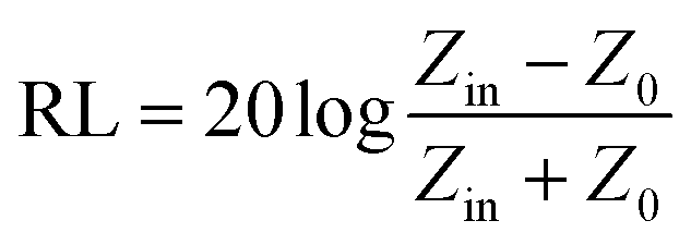
In addition, microwave absorbents with the properties such as low thickness, high bandwidth, high heat resistance, low density, reasonable price, chemical stability and the ability to cover the instrument, have the desired electrical and magnetic properties for the absorption process.64,65 The RL (reflection loss) of an electromagnetic wave is obtained when the incident waves collide in a perpendicular position to the surface of the absorbent material with a metal background (eqn (3)):
| |
 | (3) |
where, “
Z0” is the characteristic impedance of free space and “
Zin” is the input impedance at the intersection of matter and free space, which is expressed by
eqn (4):
| |
 | (4) |
where, “
c” is the electromagnetic wave velocity in the free space, “
f” and “
t” are frequency of the microwave and the thickness of the absorbent, respectively.
35 The reflection loss of an absorbent is a function of following six characteristic parameters:
f and
t′′,
μ′,
μ′′,
ε′′,
ε.
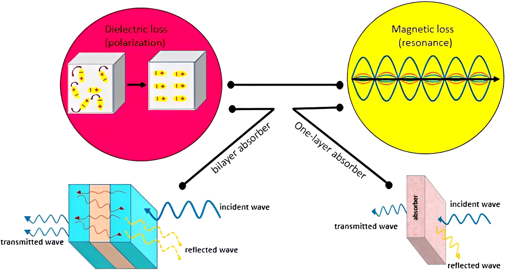
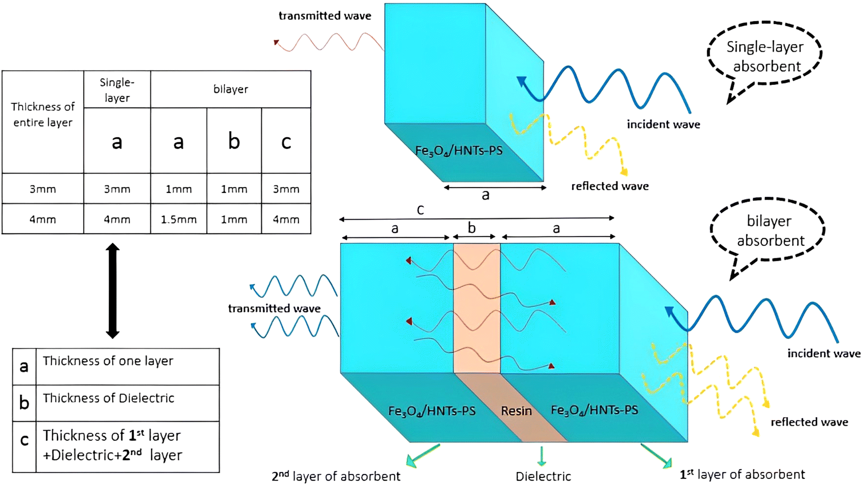
Scheme 1 shows the mechanism of microwave absorption as well as the way of radiation to the single-layer and bilayer microwave absorbent systems. The absorption mechanism includes the conditions of microwave absorption of dielectric loss and magnetic loss due to the use of PS which is a non-conductive polymer (thus conduction loss is quenched). Regarding the performance of radiation, it should be noticed that in a single-layer structure, the wave radiated to the absorbent system is absorbed, reflected and transmitted. While in the bilayer structure, in addition to the main reflection and transmission (due to the trapping the microwaves between the layers and reciprocating behavior), secondary reflection and transmission (red lines) also occur due to presence of resin as a dielectric. The single-layer absorbent has two thicknesses of 3.0 mm and 4.0 mm. It should be noted that the thickness of the resin used in the bilayer absorbent is 1.0 mm and the thickness of both sides of the absorbent is the same. It means that for the bilayer absorbent (thickness of 3.0 mm and 4.0 mm), the thickness of Fe3O4/HNT-PS magnetic nanocomposite layer is 1.0 mm and 1.5 mm, respectively. Indeed, the resin layer is not considered as a separate layer because it has very low microwave absorption performance, thus it can be ignored.37
 |
| | Scheme 1 Schematic presentation of the mechanism of microwave absorption in single-layer and bilayer structures. | |
3. Results and discussion
3.1. Preparation of Fe3O4/HNT-PS nanoabsorbent
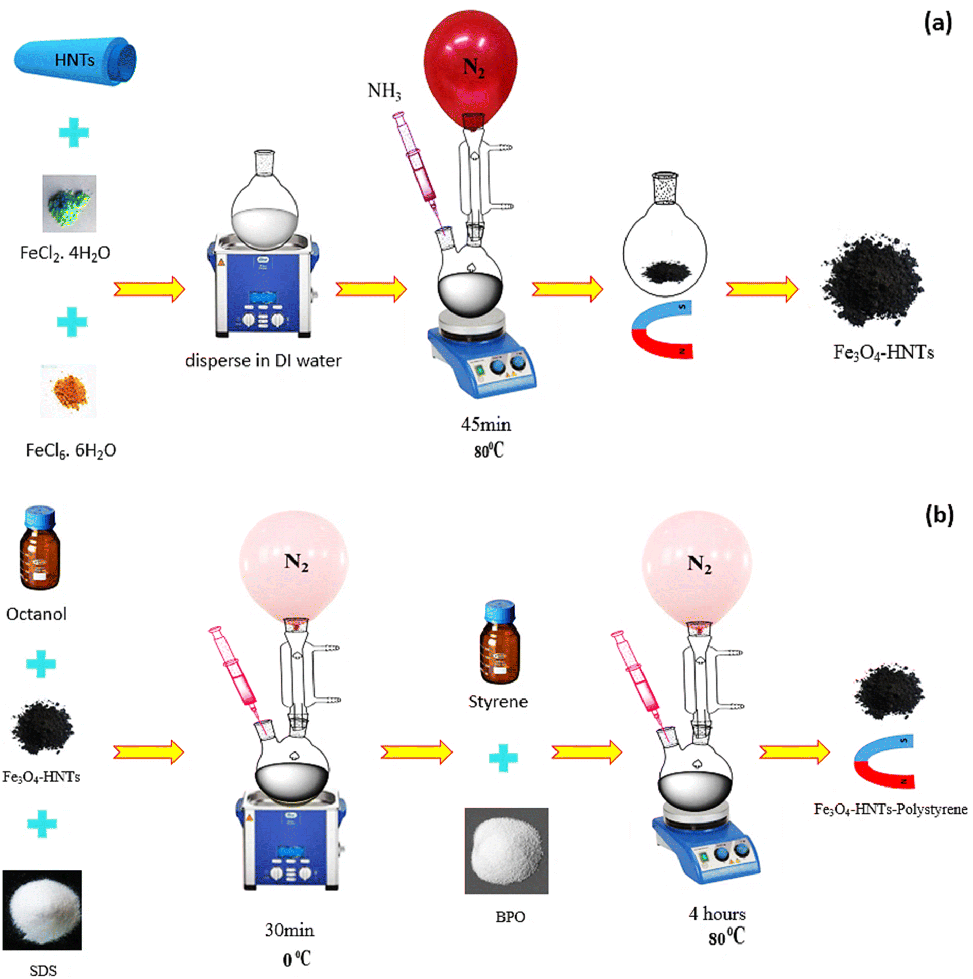
As previously discussed, several types of the materials with different structures can be applied for absorbing microwaves. In this study, iron oxide nanoparticles (Fe3O4 NPs) and halloysite nanotubes (HNTs) were used in composition with polystyrene (PS). The main target of this composition was to limit the absorption mechanisms to only magnetic and dielectric loss due to non-conductivity of the PS. Herein, co-precipitation of the iron salts (Fe2+ and Fe3+) and further polymerization of the PS through an in situ process were considered for construction of an stable composite.66,67 Scheme 2 schematically represents the preparation route of Fe3O4/HNT-PS nanoabsorbent. According to the scheme, HNTs were dispersed water via ultrasonication, and then iron salts were added into the mixture of HNTs. Co-precipitation of the Fe2+ and Fe3+ ions occurred through addition of ammonia solution through a dropwise manner. Nitrogen gas was purged into the reaction flask because oxidation by oxygen in the air may lead to the formation of γ-Fe2O3 NPs, which are less magnetic than the Fe3O4 NPs.68–70 Appearance of black particles confirmed successful preparation of Fe3O4/HNT nanoparticles. Octanol and sodium dodecyl were dissolved in water, and added to the dispersed Fe3O4/HNT particles. Afterward, styrene and benzoyl peroxide were added. At this stage, an in situ polymerization was performed by sonication (50 kHz, 100 W L−1) at 0 °C under the nitrogen flow. Finally, the prepared Fe3O4/HNT-PS particles were magnetically separated and dried. Afterward, microwave nanoabsorbents were prepared as follows: for the single-layer structure, a specific amount of Fe3O4/HNT-PS nanocomposite (turned into a powder after drying), was combined with the desired amount of epoxy resin and poured into the mold. For the bilayer structure, the single-layer absorbent was prepared twice in a thinner thickness with the epoxy resin between two layers (thickness reached 1.0 mm). These prepared samples were finally subjected to the microwave radiation.
 |
| | Scheme 2 Schematic presentation of the preparation route of (a) Fe3O4/HNT particles, and (b) Fe3O4/HNT-PS absorbent system. | |
3.2. Characterization
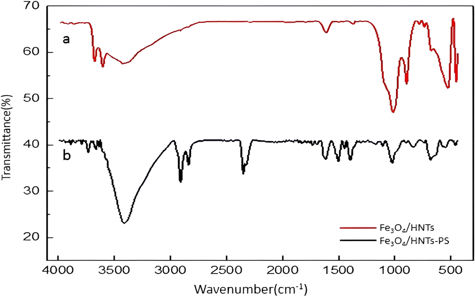
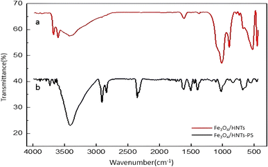
3.2.1. FTIR analysis. Fourier-transform infrared (FTIR) spectroscopy is one of the common methods to identify and determine the structural characteristics of the prepared compounds. The FTIR spectra of Fe3O4/HNT and Fe3O4/HNT-PS are illustrated in Fig. 1. The comparisons can confirm successful preparation of Fe3O4/HNT-PS nanocomposite. As can be seen in provided spectrum of Fe3O4/HNT, the bands at 3695 and 3627 cm−1 are attributed to the stretching vibrations of inner-surface Al–OH.41 The peaks related to the bending vibrations of Al–O–Si and Si–O–Si bands appeared at 536 and 468 cm−1, respectively.71,72 The strong band around 1046 cm−1 can be assigned to Si–O stretching vibration.73 In addition, the Fe3O4 characteristic peak at around 550 cm−1 overlapped with the peak related to the bending vibrations of Al–O–Si. As shown in the spectrum of Fe3O4/HNT-PS, the main characteristic peaks of HNTs are clearly seen. Also, the peaks at the areas 1441, 1516, and 1624 cm−1 are related to the C![[double bond, length as m-dash]](https://www.rsc.org/images/entities/char_e001.gif) C bond, present in the structure of styrene.74,75 Furthermore, the peak related to the stretching vibrations of C–H bonds appeared at ca. 2914 and 3000 cm−1.76
C bond, present in the structure of styrene.74,75 Furthermore, the peak related to the stretching vibrations of C–H bonds appeared at ca. 2914 and 3000 cm−1.76
 |
| | Fig. 1 FTIR spectra of the prepared (a) Fe3O4/HNT particles, and (b) Fe3O4/HNT-PS absorbent system. | |
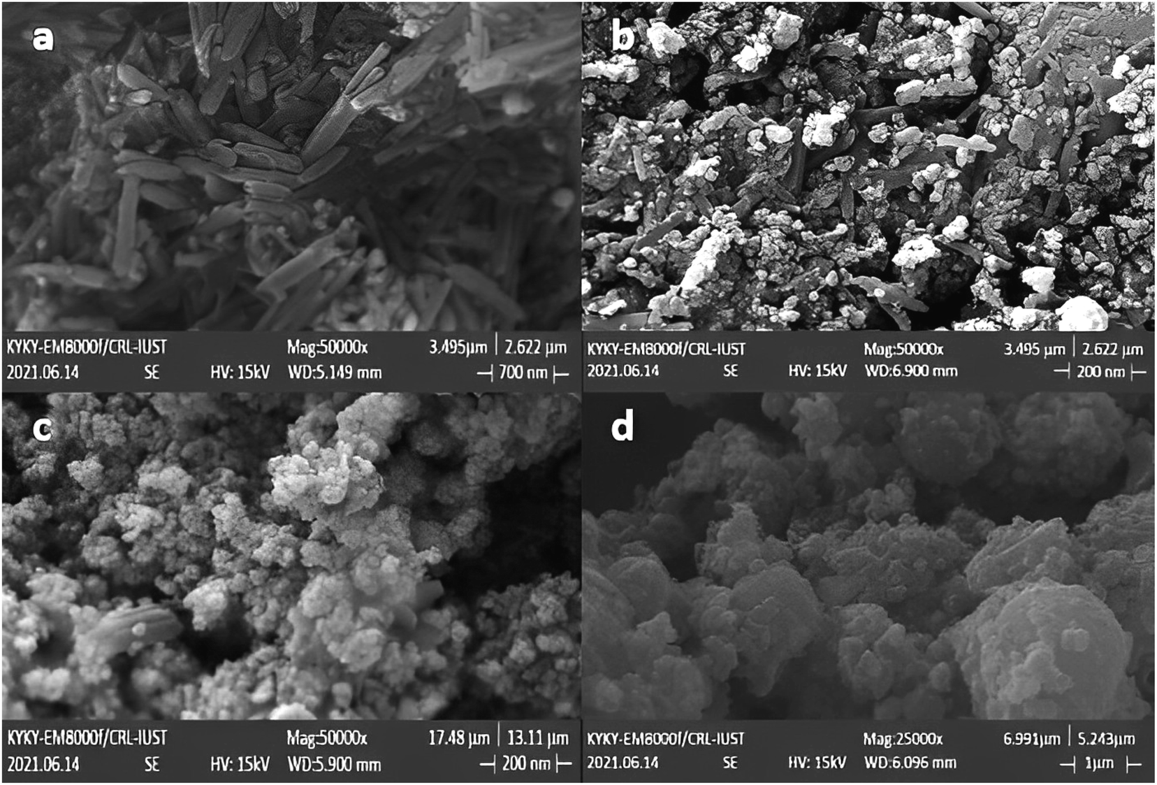
3.2.2. FESEM analysis. The morphology and size of the prepared Fe3O4 nanoparticles, Fe3O4/HNT nanoparticles and Fe3O4/HNT-PS nanocomposite were monitored with field-emission scanning-electron microscopy (FESEM). The obtained images confirmed loading of Fe3O4 and PS on HNTs surfaces (Fig. 2). The tubular structures visible in Fig. 2a are assigned to halloysite nanotubes with outer diameter of 40 to 70 nm. Also, the length of these tubes is estimated to be in a range of 100–2000 nm. The spherical particles of Fe3O4 clumped on the surface of HNTs with the average size of 60–70 nm are clearly discerned in Fig. 2b. The cluster-shapes formed by the spheres is attributed to the magnetic interactions between the particles. As is observed, the located Fe3O4 NPs onto the HNTs surfaces caused a roughness in the structure. In Fig. 2c, combination of the PS network has led to a lump-like structure showing non-uniform PS-coating on the magnetized HNTs. Fig. 2c and d illustrate that integration of the particles by the PS network created a porous lattice of the Fe3O4/HNT. Such porous lattices are suitable for the attenuation of the electromagnetic waves through absorption once the microwaves get into the close spaces.
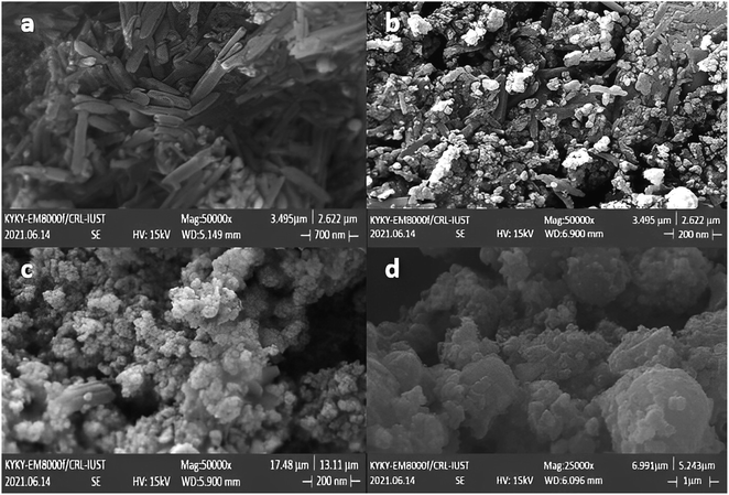 |
| | Fig. 2 FESEM images of the prepared samples: (a) HNTs, (b) Fe3O4/HNTs, and (c, d) Fe3O4/HNT-PS absorbent system. | |
3.2.3. EDX analysis. Energy-dispersive X-ray (EDX) analysis demonstrates the present elements in the structure of the prepared nanocomposite. The obtained results indicated that Fe3O4/HNT contains Fe, O, Al, and Si elements (Fig. 3a) their exact amounts are seen in related quantitative results. In addition, the presence of carbon atom is notable in Fe3O4/HNT-PS nanocomposite, confirming successful combination of PS with the Fe3O4/HNT structure that contains Fe, O, Al, Si and C elements (Fig. 3b). It should be noted that the quantitative values presented in Fig. 3 well verified the presence of the desired atoms in the compounds and also indicated the absence of impurities in the compound. It is noteworthy that the Au impurities is due to the sample preparation process for EDX and FESEM analyses. The purity of the prepared nanocomposite was confirmed by the absence of other elements.
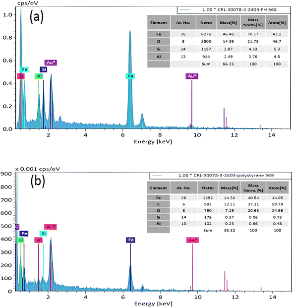 |
| | Fig. 3 EDX analyses of the (a) Fe3O4/HNTs, and (b) Fe3O4/HNT-PS absorbent system. | |
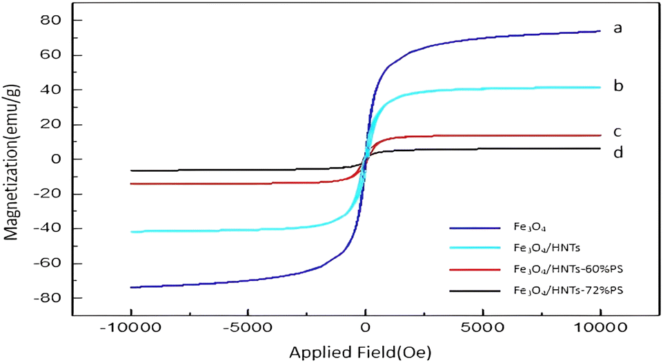
3.2.4. Vibrating-sample magnetometer (VSM). According to literature, a super-paramagnetic behavior is seen for the neat Fe3O4 NPs. This unique property exclusively belongs to the nanomaterials (below 50 nm), which are not able to form a double-domain magnetization state due to their tiny scale.77–79 The results of saturation of magnetization in prepared Fe3O4/HNT-PS nanocomposite is displayed in Fig. 4. As can be seen, the Fe3O4/HNT-PS nanocomposite has shown thin hysteresis VSM loops, so it can be classified as a soft magnetic material. Therefore, the Fe3O4/HNT-PS nanocomposite can be very easily magnetized through applying an external magnetic field, and the magnetism is lost upon removing that. This issue is also true for the iron oxide magnetic nanoparticles, which means that it can be classified as a soft ferromagnetic species due to its thin hysteresis VSM loops.37 In the hysteresis loops, the super-paramagnetic behavior of the Fe3O4 can be visible in the VSM analysis.80,81 Also, the magnetic saturation value of the prepared samples were decreased after incorporation of non-magnetic materials (like HNTs and PS). It is quite reasonable to see that the magnetic saturation values for Fe3O4, Fe3O4/HNT, Fe3O4/HNT-60% PS and Fe3O4/HNT-72% PS are 73.8, 41.6, 14 and 6.5 emu g−1, respectively.
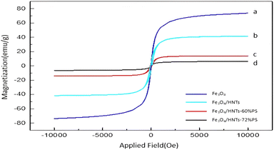 |
| | Fig. 4 Magnetization curves of the synthesized samples: (a) Fe3O4, (b) Fe3O4/HNT, (c) Fe3O4/HNT-60% PS and (d) Fe3O4/HNT-72% PS absorbent system. | |
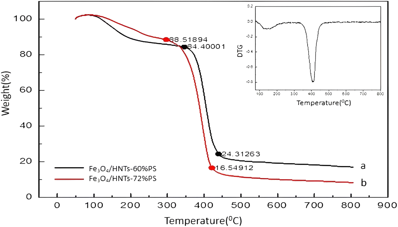
3.2.5. TGA. The thermogravimetric analysis (TGA) and derivative thermogravimetric (DTG) results provide comprehensive information about the sample's thermal stability. Based on this method, thermal degradation trend of the Fe3O4/HNT-PS nanocomposite is shown in Fig. 5. The reason for preparation of different weight percentages is to investigate the effect of the amount of each material which are used for the reflection loss. Therefore, TGA analysis will be useful to determine the amount of polymer by increasing the temperature of the prepared samples. As is observed, a 15% weight loss at the initial stage (in a range of 100–300 °C) is related to removal of the entrapped water molecules in silica layer, and also the adsorbed moisture.82 The Fe3O4/HNT-PS nanocomposite with the different weight percentage of polystyrene (60% and 72%) shown a significant weight loss in a thermal range of ca. 300 to 450 °C, which can be attributed to decomposition of the PS structure.83 According to DTG curve, a peak at about 410 °C indicates the highest mass change rate. Afterward, a fairly gradual degradation trend is seen at the temperature above 500 °C, which is related to degradation of Fe3O4 and HNTs.53 The Fe3O4 nanoparticles have good thermal stability up to 750 °C.84 Also, dehydroxylation of halloysite nanotube occurred at 480–640 °C.85 Based on these results, it can be concluded that the architecture of the Fe3O4/HNT-PS nanocomposite is stable enough to be used in the wave-absorption process for several times. In addition to above analyses, X-ray diffraction (XRD) pattern, SEM, and dynamic light scattering (DLS) curve of the neat Fe3O4 NPs were also provided for better comparison with the Fe3O4/HNTs-72% PS absorbent systems (Fig. S1–S3, in ESI file†).
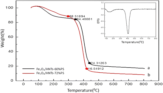 |
| | Fig. 5 The TGA analyses of the synthesized samples: (a) Fe3O4/HNTs-60% PS and (b) Fe3O4/HNTs-72% PS absorbent systems. | |
3.3. Microwave absorption properties
3.3.1. Vector network analysis. The microwave absorption spectra of the samples were provided by vector network analysis (VNA), as shown in Fig. 6. Firstly, the effects of resin, various nanocomposite systems, and sample thickness (with different amounts of nanocomposite) were precisely examined on the microwave absorption rate, and the obtained results were summarized in Table 1. Also, the details related to the thickness of the layers are presented in Scheme 3. The reflection loss (RL) of single-layer samples (samples 1 and 4) with the thickness values of 3.0 and 4.0 mm were measured. As is observed, the obtained results with the samples −5.1 dB and −6.9 dB are not so appropriate.25 For better absorption, a dielectric layer of resin was incorporated between the layers of Fe3O4/HNTs-PS composite. In this case, the nanocomposite systems Fe3O4/HNT-60% PS and Fe3O4/HNT-72% PS with a thickness value of 3.0 mm were prepared and tested (samples 2 and 7). The Fe3O4/HNT-60% PS nanocomposite with RL-11.74 dB exhibited better microwave absorption activity in comparison with the Fe3O4/HNT-72% PS system, which can be the result of using a smaller amount of a non-conductive polymer (polystyrene). As can be seen in Table 1, sample 2 containing 85 wt% of resin had a higher amount of microwave absorption with the fixed thickness of 3.0 mm. So, the sample with 85% resin was chosen as the best absorbent. In the same line, the Fe3O4/HNT-60% PS nanocomposite with 85% of resin exhibited an acceptable result, as well. The effect of the absorbent's amount using the sample with 4.0 mm was investigated, too. As presented in Table 1, sample 5 was chosen as the most efficient sample with an RL value of −26.9 dB. In fact, application of very thin layers of resin (as a dielectric material) leads to entrapment of the absorbed microwaves, as can be seen in the red simulated waves in Scheme 1. Also, as it was mentioned in its description, incorporation of a dielectric material with different physical properties between the layers of the absorbent is the main reason for efficient capture of the waves.86,87 Thus, increase in the microwave absorption is approved by sinusoidal shape of the resin diagram. Also, this feature was confirmed by microwave absorption curve (Fig. 6b), where the sinusoidal diagram is the best approval for entrapping the waves between two layers of the absorbent system. As can be seen in Fig. 6b, the absorption intensity increased by decreasing the weight percentage of the polymer due to the enhanced magnetization intensity. Also, it was observed that proportional to increasing the weight ratio of resin, the absorption rate is significantly decreased. Besides, the absorption rate was improved by increasing the thickness from 3.0 to 4.0 mm. It should be noticed that the sinusoidal shape can disclose the reason of attenuation of the wave's energy. The presence of a dielectric layer causes the microwaves to go back and forth between two absorbent layers, resulting in the change of the essence of the waves from high frequencies to lower levels.
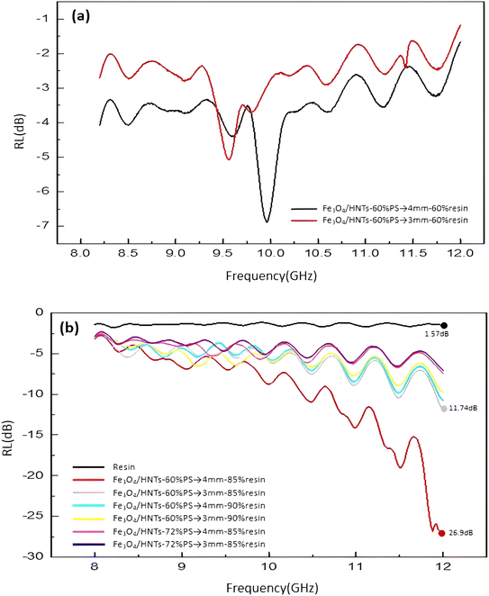 |
| | Fig. 6 Frequency dependence of the calculated RL values of the Fe3O4/HNT-PS single-layer samples (a) and Fe3O4/HNT-PS bilayer samples (b). | |
Table 1 Reflection loss values that measured and details of different samples
| Sample |
Nanocomposite |
Amount of polymer (wt%) |
Resin wt% |
Thickness (mm) |
RL (dB) |
| 1 (single-layer) |
Fe3O4/HNTs-60% PS |
60 |
60 |
3 |
−5.07 |
| 2 (bilayer) |
60 |
85 |
−11.74 |
| 3 (bilayer) |
60 |
90 |
−9.71 |
| 4 (single-layer) |
60 |
60 |
4 |
−6.88 |
| 5 (bilayer) |
60 |
85 |
−26.9 |
| 6 (bilayer) |
60 |
90 |
−10.72 |
| 7 (bilayer) |
Fe3O4/HNTs-72% PS |
72 |
85 |
3 |
−7.05 |
| 8 (bilayer) |
72 |
85 |
4 |
−7.4 |
| Pure resin |
— |
0 |
100 |
3 |
−1.7 |
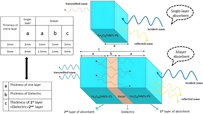 |
| | Scheme 3 Schematic presentation of the single-layer and bilayer absorbent thicknesses. | |
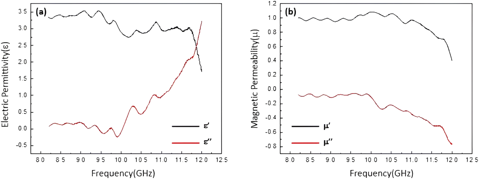
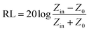
The electrical permittivity and magnetic permeability values related to sample 5 (the most efficient one) are presented in Fig. 7. According to literature, the microwave absorption performance of an absorbent system is closely in correlation with the complex permittivity (εr) and complex permeability (μr) parameters. Therefore, to emphasize that the absorption properties of a conventional absorbent is related to the electrical and magnetic properties of the involved components, electric permittivity and magnetic permeability diagrams were obtained for the prepared samples. Fig. 7a represents the complex electric permittivity as a function of frequency, where the amount of ε′ is decreasing from 1.5 to 3.5, and the amount of ε′′ is approximately from 0 to 3.25. It can be seen that proportional to increase in the frequency value from 8 to 12 GHz, the amount of ε′′ (which indicates the amount of electromagnetic energy) has lost. In fact, this amount of energy loss is converted into the heat energy.12 As presented in Fig. 7a, ε′′ is also consistent with the graph of reflection loss. Also, Fig. 7b demonstrates dependence of the frequency on μ′ and μ′′ values of the samples. μ′ and μ′′ are the imaginary and real parts of magnetic permeability that will change due to the change of the environment and the entry of microwaves into the secondary environment which has different dielectric properties.14 It is observed that the values of μ′ and μ′′ are changed according to the frequency variation. The negative values of μ′′ of the magnetic permeability (which indicates energy dissipation) can also be examined according to Wu's theory,88 which suggests that the negative values of μ′′ are ascribed to the induced magnetic energy, going out of the microwave absorbing materials. As presented in the figure, the percentage of the absorption obtained for the most efficient sample is ca. 95% of the radiated microwave.
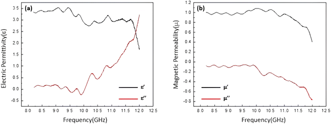 |
| | Fig. 7 Frequency dependent of the complex permittivity (a) and complex permeability (b) of the best sample: Fe3O4/HNT-60% PS with the thickness of 4.0 mm and 85% resin of the pellet. | |
3.3.2. Comparison of previous similar single-layer and bilayer systems with Fe3O4/HNT-PS. Table 2 briefly presents a survey of various types of microwave absorbent systems with almost similar compositions. It should be noticed that there would be differences between the compared systems such as utilization of two different layers in bilayer types, and the absence of dielectric between the absorbent layers. Most absorbent systems show acceptable results of microwave absorption (materials are selected based on it in studies), which are a combination of metals, magnetic nanoparticles, ferrites with carbon-based conductive polymers.14 In bilayer absorbent systems, it is expected that due to the presence of two absorbent layers and microwave collision, energy attenuation of the microwave occurs more than that of a single-layer absorbent, meaning that the value of RL is higher than the single-layer absorbent. Of course, the amount of absorption also depends on the thickness of the layers. Hence, it is reasonable to that a single-layer absorbent increases the amount of RL by increasing the thickness of the layer, but it does not mean that the optimal result will be obtained.37 The materials selected in the current work were chosen according to the investigation of the expected results to understand how the PS (as a non-conducting polymer) affects the absorption results, or what would be the effects of a bilayer absorbent with the presence of a dielectric between the layers. For better understanding of this issue, we can take two opposite mirrors as an example (at the frequency of visible light) where the light is trapped between them and constantly radiates to the opposite side, and as a result, we will heat up the surface of the mirror and absorb energy by the surface of the mirror. Comparisons made in Table 2 would be useful to quickly figure out the effectiveness of different ingredients and the architecture on the absorption results.
Table 2 Comparison of single-layer and bilayer microwave absorbents with the present research
| Materials |
Thickness/mm |
RL/dB |
Frequency/GHz |
Bandwidth (≤10 dB)/GHz |
Ref. |
| PS-PVP-Fe3O4- PEG (one layer) |
1 |
−11 |
10 |
0.3 |
89 |
| PS/TGO/Fe3O4 (one layer) |
— |
−35 |
11.9 |
4 |
90 |
| Ni@MWCNT/PS (one layer) |
6 |
−33 |
2.7 |
0.9 |
91 |
| HNTs/polypyrrole/Fe3O4 (one layer) |
3 |
−31.2 |
10.58 |
4 |
37 |
| HNTs/Fe3O4/C (one layer) |
4.56 |
−51.5 |
11 |
— |
92 |
| PBOPy/PPy/Fe3O4 (one layer) |
3.5 |
−23.3 |
13 |
2.2 |
93 |
| PEDOT/PSS/HNTs (one layer) |
4.5 |
−16.3 |
8.4 |
2 |
94 |
| Fe3O4/carbon@Fe3O4/rGO (bilayer) |
2 |
−52 |
9.4 |
4 |
95 |
| LAS@LAS-SiC (bilayer) |
4 |
−42.8 |
10.5 |
3.5 |
96 |
| Fe3O4/HNT-PS (current work) |
4 |
−26.9 |
12 |
1.27 |
— |
4. Conclusion
In this work, the prepared Fe3O4/HNTs-PS magnetic nanocomposite was investigated as a microwave absorbent system in the X-band region. Firstly, the presented system and its exclusive properties have been studied via various methods such as FTIR, TGA, EDX, VSM and FESEM. Then, the effects of magnetic and dielectric dissipative agents on the absorption process have been examined by applying polystyrene (PS), as a non-conductive polymer. Totally, three main factors affect the microwave absorption: magnetic loss, dielectric loss and conduction loss. In this research, the intention was to limit one of the mentioned factors and investigate its effectiveness. For this purpose, polystyrene (PS, as a non-conductive polymer) has been used to quench the conduction loss, and play a role in integrating other components. The observed significant reduction of RL confirmed the effect of non-conductive PS. Indeed, the use of PS (which is a non-conductive agent) has decreased the amount of microwave energy attenuation by limiting the condition of conduction loss, which is one of the most effective factors in microwave absorption. Therefore, the microwave absorption has diminuend trough incorporation of the PS into the structure. In addition, it was observed that the incorporation of a dielectric material between two layers of the absorbent material enhances the microwave absorption via entrapment of the waves between the layers. According to the obtained results, the absorption value for a single-layer absorbent system with a thickness of 4.0 mm is reduced by −20.02 dB through using a bilayer analogue. It has been corroborated that when the electromagnetic wave enters into the absorbent system, the waves between the different layers of the absorbent acts back and forth due to the presence of a dielectric material between the layers. Therefore, a considerable absorption value has been reached by losing the wave's energy. The thickness of the layers, the PS polymer, and weight percentages of the used resin were optimized in this work. Concisely, it has been observed that the best result (95% of wave's energy, −26.9 dB at 12 GHz) achieves by using a bilayer Fe3O4/HNTs-PS sample with the thickness of 4.0 mm, containing 85% of the dielectric resin and 60 wt% of the PS. Ultimately, the presented absorbent system is suggested to be scaled up for the industrial exploitation due to the low-cost raw materials, convenience of the preparation method, high performance, and also the use of multilayer absorbent by using a dielectric.
Author contributions
D. F. J. performed bench work; M. R. gave the hypothesis, provided the analyses and interpreted them, and also prepared the initial draft; R. T. L. reviewed and edited the context, revised, and improved the whole document; Z. H. participated in conceptualization and practical sections; A. M. led the whole project as the supervisor and project administrator.
Conflicts of interest
The authors declare no conflict of interest.
Acknowledgements
The authors gratefully acknowledge the partial support from the Research Council of the Iran University of Science and Technology (IUST).
References
- D. D. L. Chung, Carbon, 2012, 50, 3342–3353 CrossRef CAS.
- L. B. Kong, Z. W. Li, L. Liu, R. Huang, M. Abshinova, Z. H. Yang, C. B. Tang, P. K. Tan, C. R. Deng and S. Matitsine, Int. Mater. Rev., 2013, 58, 203–259 CrossRef CAS.
- J. Chen, Y. Li, L. Huang, C. Li and G. Shi, Carbon, 2015, 81, 826–834 CrossRef CAS.
- J. B. Anooja, K. S. Dijith, K. P. Surendran and G. Subodh, J. Alloys Compd., 2019, 807, 151678 CrossRef.
- H. Hosseini and H. Mahdavi, Appl. Organomet. Chem., 2018, 32, e4294 CrossRef.
- M. Najim, S. Puthucheri, V. Agarwala and D. Singh, Mater. Sci. Mater., 2015, 26, 7367–7377 CrossRef CAS.
- C. Tian, Y. Du, P. Xu, R. Qiang, Y. Wang, D. Ding, J. Xue, J. Ma, H. Zhao and X. Han, ACS Appl. Mater. Interfaces, 2015, 7, 20090–20099 CrossRef CAS PubMed.
- L. Vidhya and G. Subodh, J. Mater. Chem. C, 2022, 10, 969–982 RSC.
- S. Zhang, Q. Jia, Y. Zhao, H. Li and Q. Wu, J. Mater. Chem. C, 2014, 2, 18033–18039 CAS.
- L. Heng, Z. Zhang, X. Chen, S. Wang, Z. Wu, Z. Xie, Z. Tang and Y. Zou, Appl. Organomet. Chem., 2019, 33, e4991 CrossRef.
- S. H. Hosseini, S. H. Mohseni, A. Asadnia and H. Kerdari, J. Alloys Compd., 2011, 509, 4682–4687 CrossRef CAS.
- R. F. Zhuo, H. T. Feng, J. T. Chen, D. Yan, J. J. Feng, H. J. Li, B. S. Geng, S. Cheng, X. Y. Xu and P. X. Yan, J. Phys. Chem. C, 2008, 112, 11767–11775 CrossRef CAS.
- X. Lv, J. Guo, C. Zhao, Y. Wei, J. Zhang, Z. Wu and C. Gong, Mater. Lett., 2017, 201, 43–45 CrossRef CAS.
- M. Rouhi, Z. Hajizadeh, R. Taheri-Ledari, A. Maleki and M. Babamoradi, J. Mater. Sci. Eng., B., 2022, 286, 116021 CrossRef CAS.
- H. Zhao, F. Wang and L. Cui, Nanomicro Lett., 2021, 13, 208 CAS.
- Z. Wang, H. Bi, J. Liu, T. Sun and X. Wu, J. Magn. Magn. Mater., 2008, 320, 2132–2139 CrossRef CAS.
- Y. Ma, Y. Zhou, Y. Sun, H. Chen, Z. Xiong, X. Li, L. Shen and Y. Liu, J. Alloys Compd., 2019, 796, 120–130 CrossRef CAS.
- X. Liu, H. Guo, Q. Xie, Q. Luo, L. Wang and D. Peng, J. Alloys Compd., 2015, 649, 537–543 CrossRef CAS.
- P. Xu, X. J. Han, X. R. Liu, B. Zhang, C. Wang and X. H. Wang, J. Mater. Chem., 2009, 114(2–3), 556–560 CAS.
- R. Lv, F. Kang, J. Gu, X. Gui, J. Wei, K. Wang and D. Wu, Appl. Phys. Lett., 2008, 93, 223105 CrossRef.
- X. Zeng, X. Cheng, R. Yu and G. D. Stucky, Carbon, 2020, 168, 606–623 CrossRef CAS.
- J. Liu, Y. Feng and T. Qiu, J. Magn. Magn. Mater., 2011, 323, 3071–3076 CrossRef CAS.
- B. Lu, X. L. Dong, H. Huang, X. F. Zhang, X. G. Zhu, J. P. Lei and J. P. Sun, J. Magn. Magn. Mater., 2008, 320(6), 1106–1111 CrossRef CAS.
- J. R. Liu, M. Itoh and K. Machida, Appl. Phys. Lett., 2003, 83, 4017–4019 CrossRef CAS.
- X. F. Zhang, X. L. Dong, H. Huang, Y. Y. Liu, W. N. Wang, X. G. Zhu, B. Lv and G. P. Lei, Appl. Phys. Lett., 2006, 89, 053115 CrossRef.
- X. G. Liu, D. Y. Geng, H. Meng, P. J. Shang and Z. D. Zhang, Appl. Phys. Lett., 2008, 92, 173117 CrossRef.
- F. Wen, F. Zhang and Z. Liu, J. Phys. Chem. C, 2011, 115, 14025–14030 CrossRef CAS.
- J. Huo, L. Wang and H. Yu, J. Mater. Sci., 2009, 44, 3917–3927 CrossRef CAS.
- T. T. Tung, J. F. Feller, T. Kim, H. Kim, W. S. Yang and K. S. Suh, J. Polym. Sci., 2011, 50, 927–935 CrossRef.
- J. Wei, J. Liu and S. Li, J. Magn. Magn. Mater., 2007, 312, 414–417 CrossRef CAS.
- R. Zhao, K. Jia, J. Wei, J.-X. Pu and X. B. Liu, Mater. Lett., 2010, 64, 457–459 CrossRef CAS.
- R. Peymanfar, F. Norouzi and S. Javanshir, Synth. Met., 2019, 252, 40–49 CrossRef CAS.
- P. Saini, V. Choudhary, B. P. Singh, R. B. Mathur and S. K. Dhawan, Synth. Met., 2011, 161, 1522–1526 CrossRef CAS.
- S. H. Hosseini and A. A. Entezami, J. Appl. Polym. Sci., 2003, 90, 49–62 CrossRef CAS.
- B. Heidari, M. Ansari, A. Hoseinabadi, H. Jiriaee and F. Heidary, J. Mater. Sci. Mater. Electron, 2016, 28, 1028–1037 CrossRef.
- B. Jaleh, M. S. Madad, M. F. Tabrizi, S. Habibi, R. Golbedaghi and M. R. Keymanesh, J. Iran. Chem. Soc., 2011, 8, S161–S168 CrossRef.
- S. T. Maleki, M. Babamoradi, M. Rouhi, A. Maleki and Z. Hajizadeh, Synth. Met., 2022, 290, 117142 CrossRef CAS.
- A. Maleki, R. Taheri-Ledari, R. Ghalavand and R. Firouzi-Haji, J. Phys. Chem. Solids, 2020, 136, 109200 CrossRef CAS.
- J. Rahimi, R. Taheri-Ledari, M. Niksefat and A. Maleki, Catal. Commun., 2020, 134, 105850 CrossRef CAS.
- L. Vidhya and G. Subodh, J. Electron. Mater., 2020, 49, 1666–1676 CrossRef.
- M. Rouhi, M. Babamoradi, Z. Hajizadeh, S. T. Maleki and A. Maleki, Optik, 2020, 212, 164721 CrossRef CAS.
- H. Qin, C. M. Wang, Q. Q. Dong, L. Zhang, X. Zhang, Z. Y. Ma and Q. R. Han, J. Magn. Magn. Mater., 2015, 381, 120–126 CrossRef CAS.
- L. Zhou, S. Pan, X. Chen, Y. Zhao, B. Zou and M. Jin, J. Chem. Eng., 2014, 257, 10–19 CrossRef CAS.
- J. Noh, O. I. Osman, S. G. Aziz, P. Winget and J. L. Brédas, J. Mater. Chem., 2015, 27, 5856–5867 CrossRef CAS.
- G. Xi, B. Yue, J. Cao and J. Ye, Eur. J. Chem., 2011, 17, 5145–5154 CrossRef CAS PubMed.
- H.-Y. Zhu, Y. Q. Fu, R. Jiang, J.-H. Jiang, L. Xiao, G. M. Zeng, S. L. Zhao and Y. Wang, J. Chem. Eng., 2011, 173, 494–502 CrossRef CAS.
- X. Chen, Y. Zhou, H. Han, X. Wang, L. Zhou, Z. Yi, Z. Fu, X. Wu, G. Li and L. Zeng, Mater. Today Chem., 2021, 22, 100556 CrossRef CAS.
- S. Ahmad, U. Riaz, A. Kaushik and J. Alam, J. Inorg. Organomet. Polym., 2009, 19, 355–360 CrossRef CAS.
- C. Ma, C. Li, N. He, F. Wang, N. Ma, L. Zhang, Z. Lu, Z. Ali, Z. Xi, X. Li, G. Liang, H. Liu, Y. Deng, L. Xu, Z. Wang and J. Biomed, Nanotech, 2012, 8, 1000–1005 CAS.
- X. Huang, M. Lu, X. Zhang, G. Wen, Y. Zhou and L. Fei, Scr. Mater., 2012, 67, 613–616 CrossRef CAS.
- W. Zhou, X. Hu, X. Bai, S. Zhou, C. Sun, J. Yan and P. Chen, ACS Appl. Mater. Interfaces, 2011, 3, 3839–3845 CrossRef CAS PubMed.
- X. Li, B. Zhang, C. Ju, X. Han, Y. Du and P. Xu, J. Phys. Chem. C, 2011, 115, 12350–12357 CrossRef CAS.
- S. T. Maleki, M. Babamoradi, Z. Hajizadeh, A. Maleki and M. Rouhi, Micro Nano Lett., 2020, 15, 723–727 CrossRef CAS.
- R. Taheri-Ledari, M. R. Ahghari, F. Ansari, M. Forouzandeh-Malati, S. S. Mirmohammadi, S. Zarei-Shokat, S. Ramezanpour, W. Zhang, Y. Tian and A. Maleki, Nanoscale Adv., 2022, 4, 4418–4433 RSC.
- A. Maleki, Z. Hajizadeh, V. Sharifi and Z. Emdadi, J. Clean. Prod., 2019, 215, 1233–1245 CrossRef CAS.
- X. Jian, B. Wu, Y. Wei, S. X. Dou, X. Wang, W. He and N. Mahmood, ACS Appl. Mater. Interfaces, 2016, 8, 6101–6109 CrossRef CAS PubMed.
- W. Zhang, R. Taheri-Ledari, Z. Hajizadeh, E. Zolfaghari, M. R. Ahghari, A. Maleki, M. R. Hamblin and Y. Tian, Nanoscale, 2020, 12, 3855–3870 RSC.
- A. Maleki, R. Taheri-Ledari, J. Rahimi, M. Soroushnejad and Z. Hajizadeh, ACS Omega, 2019, 4, 10629–10639 CrossRef CAS PubMed.
- A. Maleki, R. Taheri-Ledari and M. Soroushnejad, ChemistrySelect, 2018, 3, 13057–13062 CrossRef CAS.
- R. Taheri-Ledari, J. Rahimi and A. Maleki, Ultrason. Sonochem., 2019, 59, 104737 CrossRef PubMed.
- R. Taheri-Ledari, W. Zhang, M. Radmanesh, S. S. Mirmohammadi, A. Maleki, N. Cathcart and V. Kitaev, Small, 2020, 16, 2002733 CrossRef CAS PubMed.
- R. Taheri-Ledari, E. Zolfaghari, S. Zarei-Shokat, A. Kashtiaray and A. Maleki, Commun. Biol., 2022, 5, 995 CrossRef CAS PubMed.
- M. Z. Kassaee, E. Motamedi and M. Majdi, J. Chem. Eng., 2011, 172, 540–549 CrossRef CAS.
- C. Xiang, Y. Pan and J. Guo, Ceram. Int., 2007, 33, 1293–1297 CrossRef CAS.
- Y. B. Feng, T. Qiu and C. Y. Shen, J. Magn. Magn. Mater., 2007, 318, 8–13 CrossRef CAS.
- M. Forouzandeh-Malati, F. Ganjali, E. Zamiri, S. Zarei-Shokat, F. Jalali, M. Padervand, R. Taheri-Ledari and A. Maleki, Langmuir, 2022, 38, 13728–13743 CrossRef CAS PubMed.
- R. Taheri-Ledari, N. Tarinsun, F. Sadat Qazi, L. Heidari, M. Saeidirad, F. Ganjali, F. Ansari, F. Hassanzadeh-Afruzi and A. Maleki, Inorg. Chem., 2023, 62, 2530–2547 CrossRef CAS PubMed.
- R. Taheri-Ledari and A. Maleki, New J. Chem., 2021, 45, 4135–4146 RSC.
- S. S. Soltani, R. Taheri-Ledari, S. M. F. Farnia, A. Maleki and A. Foroumadi, RSC Adv., 2020, 10, 23359–23371 RSC.
- R. Taheri-Ledari, J. Rahimi, A. Maleki and A. Esmail Shalan, New J. Chem., 2020, 44, 19827–19835 RSC.
- R. Taheri-Ledari, W. Zhang, M. Radmanesh, N. Cathcart, A. Maleki and V. Kitaev, J. Nanobiotechnology, 2021, 19, 1–21 CrossRef PubMed.
- Z. Hajizadeh, K. Valadi, R. Taheri-Ledari and A. Maleki, ChemistrySelect, 2020, 5, 2441–2448 CrossRef CAS.
- Z. Hajizadeh, F. Hassanzadeh-Afruzi, D. F. Jelodar, M. R. Ahghari and A. Maleki, RSC Adv., 2020, 10, 26467–26478 RSC.
- K. Buruga, J. T. Kalathi, K.-H. Kim, Y. S. Ok and B. Danil, J. Ind. Eng. Chem., 2018, 61, 169–180 CrossRef CAS.
- R. Taheri-Ledari, A. Maleki, E. Zolfaghari, M. Radmanesh, h. Rabbani, A. Salimi and R. Fazel, Ultrason. Sonochem., 2020, 61, 104824 CrossRef CAS PubMed.
- R. Taheri-Ledari and A. Maleki, J. Pept. Sci., 2020, 26, e3277 CrossRef CAS PubMed.
- R. Taheri-Ledari, F. Rasouli Asl, M. Saeidirad, A. Kashtiaray and A. Maleki, Sci. Rep., 2022, 12, 4719 CrossRef CAS PubMed.
- R. Taheri-Ledari, F. Sadat Qazi, M. Saeidirad and A. Maleki, Sci. Rep., 2022, 12, 14865 CrossRef CAS PubMed.
- F. Ganjali, A. Kashtiaray, S. Zarei-Shokat, R. Taheri-Ledari and A. Maleki, Nanoscale Adv., 2022, 4, 1263–1307 RSC.
- A. Maleki, R. Taheri-Ledari and R. Ghalavand, Comb. Chem. High Throughput Screen., 2020, 23, 119–125 CrossRef CAS PubMed.
- R. Taheri-Ledari, S. M. Hashemi and A. Maleki, RSC Adv., 2019, 9, 40348–40356 RSC.
- R. Taheri-Ledari, S. S. Mirmohammadi, K. Valadi, A. Maleki and A. E. Shalan, RSC Adv., 2020, 10, 43670–43681 RSC.
- P. Ding and B. Qu, J. Colloid Sci., 2005, 291, 13–18 CrossRef CAS PubMed.
- S. Kadi, S. Lellou, K. Marouf-Khelifa, J. Schott, I. Gener-Batonneau and A. Khelifa, Microporous Mesoporous Mater., 2012, 158, 47–54 CrossRef CAS.
- J. Chen, J. Feng and W. Yan, J. Colloid Sci., 2016, 475, 26–35 CrossRef CAS PubMed.
- Y. Danlée, I. Huynen and C. Bailly, Appl. Phys. Lett., 2012, 100, 213105 CrossRef.
- A. Oikonomou, T. Giannakopoulou and G. Litsardakis, J. Magn. Magn. Mater., 2007, 316, e827–e830 CrossRef CAS.
- H. Wu, L. Wang, Y. Wang, S. Guo and Z. Shen, J. Alloys Compd., 2012, 525, 82–86 CrossRef CAS.
- S. H. Hosseini and M. Sadeghi, Curr. Appl. Phys., 2014, 14, 928–931 CrossRef.
- Y. Chen, Y. Wang, H.-B. Zhang, X. Li, C.-X. Gui and Z.-Z. Yu, Carbon, 2015, 82, 67–76 CrossRef CAS.
- R. K. Srivastava, T. N. Narayanan, A. P. Reena Mary, M. R. Anantharaman, A. Srivastava, R. Vajtai and P. M. Ajayan, Appl. Phys. Lett., 2011, 99, 113116 CrossRef.
- S. Kaixuan, H. Zilong, L. Shupei and O. Jing, Appl. Clay Sci., 2022, 229, 106690 CrossRef.
- Y. Li, D. Chen, X. Liu, Y. Zhou, Q. Zhuang, R. Cai and K. Zhang, Compos. Sci. Technol., 2014, 100, 212–219 CrossRef CAS.
- S. J. Luo, P. Zhang, Y. A. Mei, J. B. Chang and H. Yan, J. Appl. Polym. Sci., 2016, 133(47), 44242 CrossRef.
- Q. Gang, M. Niaz Akhtar and R. Boudaghi, J. Magn. Magn. Mater., 2021, 537, 168181 CrossRef CAS.
- C.-H. Peng, P. Shiu Chen and C.-C. Chang, Ceram. Int., 2014, 40, 47–55 CrossRef CAS.
Footnote |
| † Electronic supplementary information (ESI) available: The ESI file includes the XRD pattern, SEM image, and DLS curve related to the neat iron oxide nanoparticles. See DOI: https://doi.org/10.1039/d2ra08339f |
|
| This journal is © The Royal Society of Chemistry 2023 |
Click here to see how this site uses Cookies. View our privacy policy here. 
 Open Access Article
 This Open Access Article is licensed under a
  a,
Zoleikha Hajizadeha and
Ali Maleki
a,
Zoleikha Hajizadeha and
Ali Maleki