 Open Access Article
Fabrication and property evaluation of calcium-oxide-loaded microcapsules during supplemental heat-based exploitation of natural gas hydrates
Jintang Wang *ab,
Zihua Shaoa,
Yujing Baia,
Guolei Hec,
Xudong Wangd,
Lei Liua,
Bo Liao
 a,
Xiaohui Suna,
Kaihe Lva and
Jinsheng Suna
aSchool of Petroleum Engineering, China University of Petroleum (East China), Qingdao 266580, China. E-mail: wangjintang@upc.edu.cn
bKey Laboratory of Metallogenic Prediction of Nonferrous Metals and Geological Environment Monitoring (Central South University), Ministry of Education, Changsha 410083, China
cInstitute of Exploration Techniques, Chinese Academy of Geosciences, Langfang 065000, China
dShandong Institute of Petroleum and Chemical Technology, Dongying, 257061, China
First published on 3rd March 2023
Abstract
The exploitation of natural gas hydrates (NGHs) by traditional methods is far lower than the commercial target. Calcium oxide (CaO)-based in situ supplemental heat combined with depressurization is a novel method for effectively exploiting NGHs. In this study, we propose an in situ supplemental heat method with the sustained-release CaO-loaded microcapsules coated with polysaccharide film. The modified CaO-loaded microcapsules were coated with polysaccharide films using covalent layer-by-layer self-assembly and wet modification process, with (3-aminopropyl) trimethoxysilane as the coupling agent and modified cellulose and chitosan as the shell materials. Microstructural characterization and elemental analysis of the microcapsules verified the change in the surface composition during the fabrication process. We found that the overall particle size distribution was within the range of 1–100 μm, corresponding to the particle size distribution in the reservoir. Furthermore, the sustained-release microcapsules exhibit controllable exothermic behavior. The decomposition rates of the NGHs under the effect of CaO and CaO-loaded microcapsules coated with one and three layers of polysaccharide films were 36.2, 17.7, and 11.1 mmol h−1, respectively, while the exothermic time values were 0.16, 1.18, and 6.68 h, respectively. Finally, we propose an application method based on sustained-release CaO-loaded microcapsules used for the supplemental heat-based exploitation of NGHs.
1. Introduction
Natural gas hydrates (NGHs), an unconventional source of natural gas, are distributed in deep-water and continental permafrost areas. NGHs produce an insignificant amount of carbon dioxide and water only after combustion and thus cause much less pollution than coal and petroleum. In addition, NGH reserves are enormous and are estimated at ∼2 × 10¹⁶ m3 worldwide, which is 2.84 times more than the global reserves of non-renewable energy sources (e.g., coal, petroleum, and natural gas). Therefore, NGHs are universally recognized as having significant potential to become an efficient and clean alternative energy source and thus will play a strategically crucial role in advancing the global energy revolution.1–5NGH reserves have been preliminarily estimated at ∼1100 × 108 tonnes of oil equivalent (toe) in China, of which ∼800 × 108 tonnes of NGH reserves are located in the sea areas of China, accounting for twice the amount of conventional natural gas resources found in China. Natural gas has advantages over coal and petroleum, such as high calorific values, low carbon emissions, no waste residues and no wastewater produced after combustion, and high safety. In the future, the petroleum demand is expected to continuously decrease, resulting in natural gas becoming a major supplementary energy source. As a bridge energy source that drives the transition from conventional to clean energy, natural gas will play a leading role in promoting the transformation of the energy mix and will be vital toward establishing a low-carbon, environmentally friendly, safe, and efficient energy system in China, as well as realizing China's goals of peaking carbon dioxide emissions before 2030 and achieving carbon neutrality before 2060.6,7
Currently, China relies heavily on natural gas imports, with considerable unmet demand for natural gas in China. Although practical experience has been accumulated and theoretical techniques have been developed after multiple attempts to perform the trial exploitation of NGHs worldwide,8–10 a complete theoretical system is still lacking to guide the exploitation and utilization of NGHs. Most theoretical systems are still being verified, while the current exploitation methods are subject to limitations (e.g., low production efficiency, harsh exploitation conditions, expensive materials, high environmental risk, phase changes in sand production and wellbore, and unstable production). Thus, according to the current situation, it is challenging to achieve the safe and effective commercial exploitation of NGHs, and the exploitation of NGHs needs to be improved. Commercially exploiting NGHs is currently a well-explored research area.
A novel exploitation method was proposed for NGHs using calcium oxide (CaO) as the in situ supplemental heat source.11 This method can directly inject CaO into the fractures of the NGH reservoir to react exothermically with water to promote the decomposition of the NGHs and supplement the decreased amount of heat in the reservoir during the later stage of decompression-based exploitation of NGHs. The reaction product is calcium hydroxide, which is highly permeable and can effectively fill up the pore spaces formed after the decomposition of the NGHs. The key to employing CaO as the supplemental heat source is controlling or reducing its exothermic rate during the hydration process to ensure compliance with project requirements. If the exothermic rate of CaO in an aqueous solution is too high, a massive amount of the heat liberated will be lost in the wellbore, leading to failure in effectively injecting CaO into the formation to promote NGH decomposition. Using an alcohol-based vehicle to inject CaO into the formation will lead to increased operational costs and combustion-related safety and environmental issues. To date, delaying the exothermic process of CaO has been rarely investigated. The surface modification of CaO can help increase the exothermic duration from 25 to 75 min.12–14 Since the 1980s, microencapsulation has been successfully applied to the pharmaceutical field, followed by extensive application and development in the food, chemical, and textile industries. Microencapsulation can be applied to encapsulate active molecules to isolate and protect them, release them in a controlled manner, and improve their compatibility and dispersion. As CaO reacts exothermically with water, microencapsulation application to the field of CaO has not been reported to date.
In this study, we have proposed a layer-by-layer (LbL) film coating method to fabricate CaO-loaded microcapsules and modified the CaO powdered surface to make its surface hydrophobic to physically block the flow of water. The surface modification and multilayer coating of CaO powder were mainly achieved by the coating, adsorption, and reaction of surface modifiers (or surface treatment and coating agents) on the powdered particle surface. CaO-loaded microcapsules, with good prospects for large-scale commercial production due to their advantages of low cost, easily accessible raw materials, and mild reaction conditions, can be injected into the reservoir using the water-based fracturing fluid, in which CaO is released in a sustained release manner to react exothermically. This strategy will significantly contribute to the effective exploitation of NGHs.
2. Materials and methods
2.1 Materials
Table 1 shows the main materials used in this study. The amino silane coupling agent was used for the surface modification of CaO, and the chitosan and cellulose powder were used for the layer-by-layer assembly process.| S/N | Name | Purity | Manufacturer |
|---|---|---|---|
| 1 | Chitosan | Analytical pure | Macklin |
| 2 | NaIO4 | 99.5% | Macklin |
| 3 | Cellulose powder | Analytical pure | Aladdin |
| 4 | (3-Aminopropyl)trimethoxysilane | 97% | Macklin |
| 5 | CaO | Analytical pure | Macklin |
| 6 | Anhydrous ethanol | ≥ 99.7% | Aladdin |
| 7 | Sodium chloride | Analytical pure | Sinopharm Hushi |
2.2 Apparatus
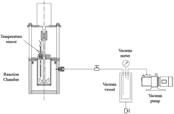
Table 2 shows the main apparatus used in this study. An experimental apparatus is used for evaluating the heat release behavior of calcium oxide and microcapsules, as given in Fig. 1. 50 mL of pure water or 3.5 wt% sodium chloride solution was put in the chamber, and mixed with calcium oxide or microcapsules at a ratio of 20 wt%. The outer annular space around the chamber is vacuumed to eliminate the temperature fluctuation by the change of room temperature.| S/N | Name | Model | Manufacturer |
|---|---|---|---|
| 1 | Magnetic stirring apparatus | MS-M-S16 | Scilogex, United States |
| 2 | High-speed centrifuge | TG16-WS | Cence, China |
| 3 | Laser particle size analyzer | Mastersizer 3000 | Malvern, United Kingdom |
| 4 | Transmission electron microscope | JEOL JEM 2100F | JEOL, Japan |
| 5 | Scanning electron microscope | Regulus8100 | Hitachi High-Tech Scientific Solutions (Beijing) Co., Ltd |
2.3 Synthesis method and principle of CaO-loaded microcapsules
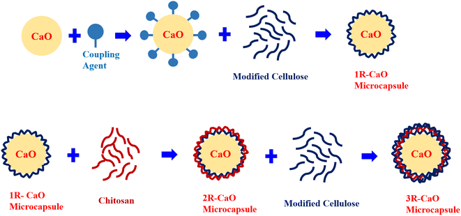
In this study, CaO-loaded microcapsules were synthesized using an layer-by-layer film coating method with CaO utilized as the core and multi-aldehyde cellulose and chitosan used as the shell materials. The layer-by-layer films were sequentially deposited to fabricate novel materials and the driving forces include electrostatic interactions, hydrogen bonding, and other functional bonding interactions formed during the layer-by-layer film coating process. Chitosan can react with other materials via several interactions (e.g., hydrogen bonding and Schiff base linkages), theoretically supporting the feasibility of fabricating chitosan-based composites via the layer-by-layer film coating process.15The Schiff base linkage is a dynamic covalent bond formed between amino and aldehyde groups, which can serve as the driving force to construct functional polysaccharide films and has advantages over other non-covalent interactions formed during the layer-by-layer film coating process. Specifically, Schiff base linkages can help construct films that are highly stable under unfavorable conditions and can be formed in an aqueous or inorganic solution and between the unreacted active and functional groups (e.g., aldehyde and amino groups) in multilayered films, which can be further used to realize the ideal properties and applications of the final materials.
Silicon hydroxyl groups formed via the hydrolysis of the amino silane coupling agent form hydrogen bonds with the hydroxyl groups on the CaO surface and undergo dehydration and condensation reactions to produce covalent –Si–O–R bonds (R denotes CaO). The hydrophobic groups of the silane coupling agent are grafted onto the CaO surface to form coatings to obtain hydrophobic surface-modified CaO (R–CaO). The functional amino groups on the R–CaO surface can be stably linked via Schiff base linkages to the aldehyde groups of multi-aldehyde cellulose. The Schiff base reaction can occur between the functional amino groups on the molecular chain of chitosan and active substances with the aldehyde groups, and multilayered films can be effectively coated using the Schiff-based layer-by-layer coating principle to provide long-lasting hydrophobic effects. Fig. 2 shows the layer-by-layer coating process.
2.4 Synthesis of CaO-loaded microcapsules
![[thin space (1/6-em)]](https://www.rsc.org/images/entities/char_2009.gif) :
:![[thin space (1/6-em)]](https://www.rsc.org/images/entities/char_2009.gif) 5. Fig. 3 shows the reaction mechanism for the oxidation of cellulose using NaIO4. After magnetic stirring for 6 h at 20 °C under dark conditions, 3.5 mL of ethylene glycol was added, and the solution was stirred for 30 min to terminate the oxidation reaction. Five volume equivalents of absolute ethanol were added to the reaction mixture for precipitation. The suspension was subjected to 10 min of vacuum drying in an electrothermal blowing drying oven heated at 40–60 °C to obtain the multi-aldehyde cellulose powder.
5. Fig. 3 shows the reaction mechanism for the oxidation of cellulose using NaIO4. After magnetic stirring for 6 h at 20 °C under dark conditions, 3.5 mL of ethylene glycol was added, and the solution was stirred for 30 min to terminate the oxidation reaction. Five volume equivalents of absolute ethanol were added to the reaction mixture for precipitation. The suspension was subjected to 10 min of vacuum drying in an electrothermal blowing drying oven heated at 40–60 °C to obtain the multi-aldehyde cellulose powder.
![[thin space (1/6-em)]](https://www.rsc.org/images/entities/char_2009.gif) :
:![[thin space (1/6-em)]](https://www.rsc.org/images/entities/char_2009.gif) 1. CaO (20 g) was fully dispersed in the silane coupling agent solution, followed by stirring for 40 min at a stirring rate of 200 rpm. The resulting dispersion was centrifuged at 8000 rpm for 10 min and then subjected to 10 min of vacuum drying in an electrothermal blowing drying oven heated at 70–90 °C to obtain R–CaO.
1. CaO (20 g) was fully dispersed in the silane coupling agent solution, followed by stirring for 40 min at a stirring rate of 200 rpm. The resulting dispersion was centrifuged at 8000 rpm for 10 min and then subjected to 10 min of vacuum drying in an electrothermal blowing drying oven heated at 70–90 °C to obtain R–CaO.![[thin space (1/6-em)]](https://www.rsc.org/images/entities/char_2009.gif) :
:![[thin space (1/6-em)]](https://www.rsc.org/images/entities/char_2009.gif) 1. R–CaO was then added into the dispersion of multi-aldehyde cellulose, followed by magnetically stirring for 20 min at a stirring rate of 200 rpm to obtain a suspension. The suspension was centrifuged at 8000 rpm for 10 min, and the collected product was dried at 70–90 °C for 10 min to obtain the CaO-loaded microcapsule coated with a layer of film (1R–CaO). 1R–CaO was then mixed and stirred in the dispersion of chitosan at a stirring rate of 200 rpm for 20 min to obtain a suspension, which was centrifuged at 8000 rpm for 10 min. The collected product was subjected to 10 min of vacuum drying in a vacuum drying oven heated at 70–90 °C to obtain the CaO-loaded microcapsule coated with two layers of film. The same operations were repeated until the CaO-loaded microcapsules coated with specific layers of films were obtained. The CaO-loaded microcapsules coated with multiple layers of films (nR-CaO; n denotes the number of assembled layers) were dried at 70 °C before use.
1. R–CaO was then added into the dispersion of multi-aldehyde cellulose, followed by magnetically stirring for 20 min at a stirring rate of 200 rpm to obtain a suspension. The suspension was centrifuged at 8000 rpm for 10 min, and the collected product was dried at 70–90 °C for 10 min to obtain the CaO-loaded microcapsule coated with a layer of film (1R–CaO). 1R–CaO was then mixed and stirred in the dispersion of chitosan at a stirring rate of 200 rpm for 20 min to obtain a suspension, which was centrifuged at 8000 rpm for 10 min. The collected product was subjected to 10 min of vacuum drying in a vacuum drying oven heated at 70–90 °C to obtain the CaO-loaded microcapsule coated with two layers of film. The same operations were repeated until the CaO-loaded microcapsules coated with specific layers of films were obtained. The CaO-loaded microcapsules coated with multiple layers of films (nR-CaO; n denotes the number of assembled layers) were dried at 70 °C before use.3. Results and discussion
3.1 Microstructural analysis of CaO-loaded microcapsules
As the elements on the surface of the CaO particles were widely distributed during microcapsule fabrication, the elements on the surface of the CaO-loaded microcapsule coated with three layers of films (3R–CaO) were analyzed using transmission electron microscopy (TEM, JEOL JEM 2100F, Japan) and energy-dispersive X-ray spectrometry (EDS). EDS can detect elements in the range of several hundred nanometers through several micrometers. The wall thickness of the microcapsules is generally within the range of 150 nm to 2.7 μm;16–18 thus, EDS can effectively detect whether the coating is formed on the CaO surface. The elements were analyzed four times at each site using EDS to eliminate the effects of random factors, with the results shown in Fig. 4 and Table 3. Silicon introduced by the surface modification step was found to be evenly distributed on the CaO surface, increasing the surface hydrophobicity and providing reaction sites for the subsequent film coatings. After subsequent coating steps, the Si content on the CaO surface was only 0.33%. Nitrogen was primarily derived from chitosan and its content was ∼0% due to the outermost layer of 3R–CaO comprising oxidized cellulose. Carbon and some of the oxygen were principally derived from the outer layer composed of multi-aldehyde cellulose, and the proportion of O was far higher than that of Ca (45.80 vs. 26.76%), suggesting that the polysaccharide films were effectively coated on the CaO surface. The changes in the surface elemental composition in the different manufacturing processes correspond to the theoretical results obtained for the surface modification and layer-by-layer assembly process.19,20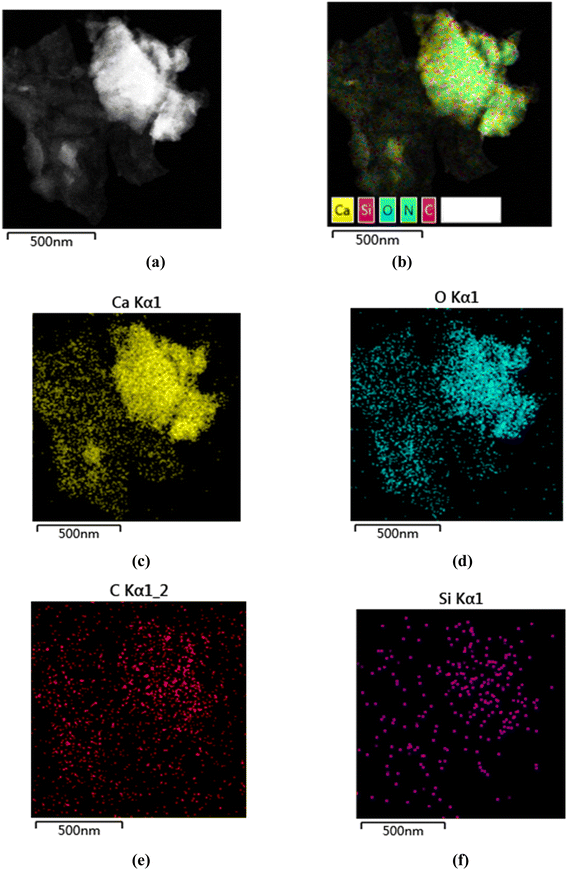 | ||
| Fig. 4 TEM-EDS images of the elemental distribution of 3R–CaO: (a) 3R CaO, (b) 3R CaO, (c) Ca, (d) O, (e) C, and (f) layered EDS image of Si. | ||
| Elements | Line type | k-factor | k-factor type | Absorption correction | wt% | wt% Sigma | At% |
|---|---|---|---|---|---|---|---|
| C | K line | 2.739 | Theory | 1.00 | 15.21 | 0.69 | 27.11 |
| N | K line | 3.477 | Theory | 1.00 | 0.00 | 0.00 | 0.00 |
| O | K line | 1.998 | Theory | 1.00 | 34.24 | 0.59 | 45.80 |
| Si | K line | 1.000 | Theory | 1.00 | 0.43 | 0.11 | 0.33 |
| Ca | K line | 0.982 | Theory | 1.00 | 50.11 | 0.61 | 26.76 |
| Total | — | — | — | — | 100.00 | — | 100.00 |
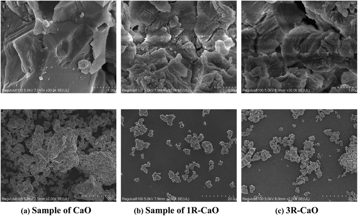
The sample surface morphologies of CaO, 1R–CaO, and 3R–CaO fabricated using absolute ethanol as the dispersant were observed using SEM (Fig. 5). Fig. 5a shows that the CaO crystals have regular and smooth surfaces. After the surface modification and multilayer coating process, the particle surface becomes rougher and gradually loses its edges and corners.21 Covalent bonding and physical adsorption of the polysaccharide coating lead to an increase in the particle surface roughness. As the thickness of coated films on the irregular particle surface is anisotropic, the particle morphologies become increasingly irregular during the assembly process.
3.2 Structural properties of sustained-release CaO-loaded microcapsules
The particle size distributions of CaO and CaO-loaded microcapsules in absolute ethanol were observed using a laser particle size analyzer (Malvern Mastersizer 3000). Fig. 6 shows the curves and histogram obtained for the cumulative particle size distributions of CaO, 1R–CaO, and 3R–CaO in absolute ethanol. Under the same conditions, the particle size of the coated CaO increased slightly; the particle size of 3R–CaO was greater than the particle sizes of 1R–CaO and CaO, and the overall particle size distribution was within the range of 1–100 μm. When the cumulative volume fractions were 10, 50, and 90%, the particle sizes of CaO, 1R–CaO, and 3R–CaO were 2.47, 2.86, and 2.99 μm, 14.5, 19.3, and 20.5 μm, and 56.2, 72.5, and 91 μm, respectively. The larger particle size indicates that a more effective coating was formed during the first two steps of the Schiff base reaction.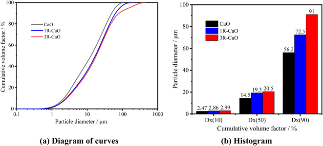 | ||
| Fig. 6 Curves and histograms obtained for the pre-reaction cumulative particle size distributions of CaO, 1R–CaO, and 3R–CaO. | ||
To further analyze the effects of water on the particle size of the CaO-loaded microcapsules, the particle size distributions of CaO and the CaO-loaded microcapsules were observed on a Malvern Mastersizer 3000 after being fully reacted with distilled water. Fig. 7 shows the curves and histogram obtained for the cumulative particle size distributions of CaO, 1R–CaO, and 3R–CaO in distilled water. CaO and the R–CaO-loaded microcapsules swell in water and react exothermically with water, and the microcapsules exhibit increased particle sizes after being soaked in distilled water. Specifically, the increased particle size of 3R–CaO was greater than that of CaO; particle sizes for D10 of CaO and 3R–CaO were 2.58 and 4 μm, respectively; particle sizes for D50 of CaO and 3R–CaO were 15.6 and 26.4 μm, respectively; particle sizes for D90 of CaO and 3R–CaO were 73.9 and 128 μm, respectively. The pore sizes in the NGH reservoir are primarily distributed between 10–100 μm.22 During their application, the particle sizes of CaO for the coated layers were appropriately controlled based on the pore throat structure of the NGH reservoir to correspond to the particle size distribution of the reservoir. The calcium hydroxide produced after the reaction could effectively fill up the pore spaces in the reservoir and support the rock matrix.
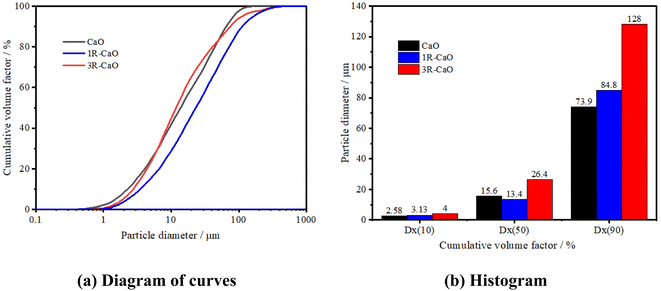 | ||
| Fig. 7 Curves and histograms obtained for the cumulative particle size distribution of CaO, 1R–CaO, and 3R–CaO after their reaction with distilled water. | ||
3.3 Exothermic properties of sustained-release CaO-loaded microcapsules
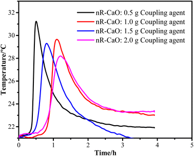
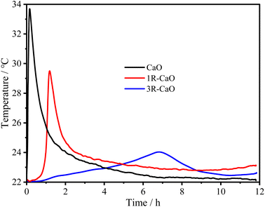
To obtain the optimal coupling agent dosage, the R–CaO samples were prepared using coupling agent dosages in the range of 0.5–2.0 g based on a gradient of 0.5 g before the exothermic test was conducted, as shown in Fig. 8. Specifically, the exothermic peak time (∼1.1 h) of R–CaO prepared using 1.0 g of coupling agent was longer than that of R–CaO prepared using 0.5 and 1.5 g of the coupling agent. It is noteworthy that the R–CaO prepared using 2.0 g of the coupling agent has a slightly longer exothermic peak time and lower peak temperature than the R–CaO prepared using 1.0 g of coupling agent. Based on comprehensive considerations of the cost and effects, using 1.0 g of coupling agent to prepare R–CaO should be preferred.Fig. 9 shows the exothermic effects of CaO, 1R–CaO, and 3R–CaO. Specifically, the peak temperature time values for CaO, 1R–CaO, and 3R–CaO are 0.16, 1.18, and 6.86 h, respectively, suggesting that the exothermic time of the CaO-loaded microcapsules coated with layers of films was significantly increased. In addition, the different particle sizes lead to different film thicknesses, rendering particles hydrophobic to varying degrees. Therefore, the heat of the reaction was gradually released throughout the process and the delay effects of R–CaO increased with an increasing number of assembled layers, as depicted by the exothermic curves. Based on the synergistic effects of the surface modification and layer-by-layer film coating process, the polysaccharide films help to significantly reduce the direct contact between water and the R–CaO surface. Schiff base films, which possess self-healing properties, can help maintain the balance between valence bond rupture and reformation when the outer coating of CaO is destroyed to prevent the continuous ingress of water.23
3.4 Analysis of the decomposition rate of NGHs subjected to the effects of sustained-release CaO-loaded microcapsules
After CaO is injected into the formation for actual operation, methane gas and water will be released as the NGHs decompose; the heat liberated when CaO reacts with water can sufficiently supplement the amount of heat needed to be absorbed when the NGHs decompose. In this experiment, the temperature curve should convert into an exothermic curve, which should then be converted to the amount of heat necessary to decompose the NGHs to plot the prediction curve for the amount of decomposed NGHs.24The amount of heat liberated when the reaction of CaO takes place in the reactor can be calculated using the following formula:
| QCaO = Qout + QH2O | (1) |
The amount of heat absorbed by water can be calculated using the specific heat capacity formula as follows:
| QH2O = cmΔT = cm(T2 − T1) | (2) |
The exothermic reaction formula for CaO is shown below:
| CaO(s) + H2O(l) = Ca(OH)2(l) ΔrHm = −64.9 kJ mol−1 | (3) |
Computational findings show that the amount of heat liberated when 6 g of CaO fully reacts with water is theoretically QCaO = 6944 J.
Gas hydrate heat of dissociation:25
 | (4) |
 | (5) |
Fig. 10 shows the results calculated by the aforementioned formulas. Specifically, the actual amounts of heat liberated during the reactions of CaO, 1R–CaO, and 3R–CaO are close to that calculated theoretically and can thus be used to predict the amount of decomposed NGHs. In addition, 6 g of CaO can cause 127 mmol of NGHs to be decomposed, while the decomposition rates of the NGHs subjected to the effects of CaO, 1R–CaO, and 3R–CaO are 36.2, 17.7, and 11.1 mmol h−1, respectively, indicating that the R–CaO-loaded microcapsules can effectively reduce the reaction and exothermic rates of CaO in water to delay the reaction and heat released and can be injected into the reservoir and effectively utilized.
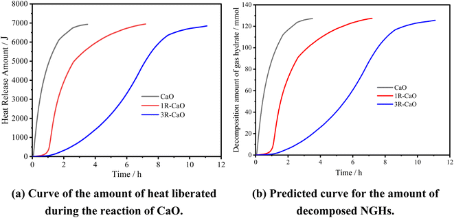 | ||
| Fig. 10 Prediction curves obtained based on the amount of heat liberated during the reaction of CaO and the amount of decomposed NGHs. | ||
3.5 Construction process based on sustained-release CaO-loaded microcapsules for supplemental heat-based exploitation
The construction process based on depressurization and filling combined with in situ supplemental heat for the exploitation of NGHs primarily includes the following steps: (1) construction begins after the wellbore is drilled and the gas flow channel connecting the reservoir to the wellhead is established; (2) NGH reservoir is reconstructed and perforations are created in the reservoir section to form perforated fractures in the NGH reservoir. Based on the saturation of the NGHs in the reservoir, the fracturing fluid carries the sustained-release CaO-loaded microcapsules with a given concentration into the perforated fractures, the spaces are extended along the perforated fractures in the reservoir, and the high-pressure fracturing fluid carries the sustained-release CaO-loaded microcapsules into the fracturing spaces. The synthesis method including the modification method and the number of layers of CaO microcapsules are determined based on the required time for it to reach hydrate formation. (3) depressurization is performed for exploitation. After the fracturing operations are discontinued, the pressure at the wellhead is reduced, and the water in the wellbore is pumped out, after which the pressure at the fractures of the NGH reservoir is reduced, and the NGHs are decomposed into natural gas and water. The films coated on the outer layer of the sustained-release CaO-loaded microcapsules are then released in a sustained manner, while CaO in the spaces partially reacts with water to produce calcium hydroxide with a considerable amount of heat released to supplement the amount of heat necessary for decomposing NGHs. As exploitation proceeds, the hydrate saturation near wellbore is lower than the further area, and CaO microcapsules with a longer heat release time can be used to maximize the efficiency of heat supplement to hydrate dissociation. The calcium hydroxide produced after the reaction is mixed with sediments to form highly permeable calcium hydroxide fillers that can be used to fill up pore spaces to sustain fracture stability and ensure that water in the wellbore can be pumped out and the NGHs can be exploited (Fig. 11).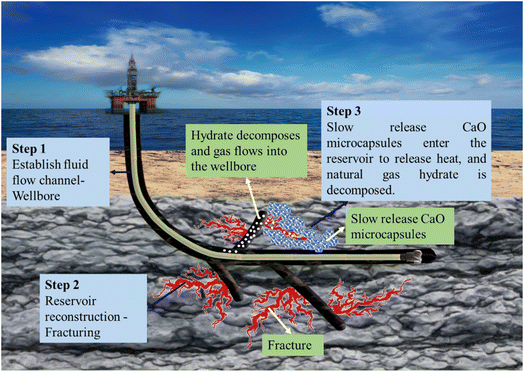 | ||
| Fig. 11 Schematic representation of the construction process based on the sustained release of CaO-loaded microcapsules for supplemental heat-based exploitation. | ||
4. Conclusions
(1) R-CaO-loaded microcapsules coated with multiple layers of polysaccharide films were fabricated using a covalent layer-by-layer self-assembly and wet modification process, with (3-aminopropyl) trimethoxysilane used as the coupling agent and cellulose and chitosan utilized as the shell material. Scanning electron microscopy and elemental analysis showed that the surface modifiers and film materials were coated via chemical adsorption on the CaO surface. In addition, we verified the gradual change in the surface compositions during the fabrication process and found that the overall particle size distribution was within the range of 1–100 μm, corresponding to the particle size distribution in the reservoir.(2) The sustained-release microcapsules show significant exothermic effects. Based on CaO, 1R–CaO, and 3R–CaO, the decomposition rates of the NGHs were 36.2, 17.7, and 11.1 mmol h−1, respectively, while the exothermic time were 0.16, 1.18, and 6.68 h, respectively.
(3) We employed CaO-loaded microcapsules and depressurization to exploit NGHs and proposed a construction process based on depressurization and filling combined with in situ supplemental heat for exploiting NGHs, thereby providing a theoretical and technical basis for effectively exploiting NGHs.
Conflicts of interest
The authors declare that they have no known competing financial interests or personal relationships that could have appeared to influence the work reported in this paper.Acknowledgements
This work was supported by the National Key Research and Development Program of China (2021YFC2800803), the National Natural Science Foundation of China (52274025, 51991361), and CNPC's Major Science and Technology Projects (ZD2019-184-003), the Key R & D Program of Shandong Province (2020ZLYS07), the Open Research Fund Program of Key Laboratory of Metallogenic Prediction of Nonferrous Metals and Geological Environment Monitoring (Central South University), Ministry of Education (Grant number 2021YSJS03).References
- B. Liao, J. T. Wang and X. P. Han, et al., Microscopic molecular insights into clathrate methane hydrates dissociation in a flowing system, Chem. Eng. J., 2022, 430, 133098 CrossRef CAS.
- Y. Qin, L. Shang and Z. Lv, et al., Methane hydrate formation in porous media: Overview and perspectives, J. Energy Chem., 2022, 74, 454–480 CrossRef CAS.
- X. Qin, C. Lu and P. Wang, et al., Hydrate phase transition and seepage mechanism during natural gas hydrates production tests in the South China Sea: A review and prospect, China Geol., 2022, 2, 201–217 Search PubMed.
- G. Jiang, J. Sun and Y. He, et al., Novel Water-Based Drilling and Completion Fluid Technology to Improve Wellbore Quality During Drilling and Protect Unconventional reservoirs, Engineering, 2022, 18(11), 129–142 CrossRef CAS.
- B. Li, X. Ma and G. Zhang, et al., Enhancement of gas production from natural gas hydrate reservoir by reservoir stimulation with the stratification split grouting foam mortar method, J. Nat. Gas Sci. Eng., 2020, 81, 103473 CrossRef CAS.
- Z. H. Shao, J. T. Wang, K. H. Lv, B. Liao, Z. L. Wang, Y. J. Bai, R. Wang and J. S. Sun, Experimental and molecular dynamics studies of zwitterionic inhibitors of methane hydrate dissociation, Fuel, 2022, 318, 123059 CrossRef CAS.
- J. S. Sun, Y. F. Cheng and X. W. Qin, et al., Research Progress on Natural Gas Hydrate Drilling & Production in the South China Sea, Sci. Bull., 2021, 35(6), 940–951 Search PubMed.
- Y. Liao, X. Sun and B. Sun, et al., Geothermal exploitation and electricity generation from multibranch U-shaped well–enhanced geothermal system, Renewable Energy, 2021, 163, 2178–2189 CrossRef.
- X. Qin, Q. Liang and J. Ye, et al., The response of temperature and pressure of hydrate reservoirs in the first gas hydrate production test in South China Sea, Appl. Energy, 2020, 278, 115649 CrossRef CAS.
- J. Ye, X. Qin and W. Xie, et al., Main progress of the second gas hydrate trial production in the South China Sea, China Geol., 2020, 47(3), 557–568 CAS.
- S. Li, X. Li and S. Wang, et al., A novel method for natural gas hydrate production: Depressurization and backfilling with in situ supplemental heat, J. Eng. Geol., 2022, 28(2), 282–293 Search PubMed.
- S. Liu, Y. Wei and B. Li, et al., Microstructural and hydration resistance study of CaO with powder surface modification by Al coupling agents: Alkoxy type and phosphate type, Ceram. Int., 2021, 47(13), 18699–18707 CrossRef CAS.
- Z. Liu, Y. Weng and Z. Huang, et al., Manufacture of a hydrophobic CaO/polylactic acid composite, Mater. Manuf. Processes, 2019, 34(3), 303–311 CrossRef CAS.
- Z. Shao, J. Wang and E. Wang, et al., Layer-by-layer self-assembled calcium oxide microcapsules with polysaccharide films for natural gas hydrate exploitation, Chem. Eng. J., 2022, 449, 137506 CrossRef CAS.
- B. Hu, Y. Guo and H. Li, et al., Recent advances in chitosan-based layer-by-layer biomaterials and their biomedical applications, Carbohydr. Polym., 2021, 271, 118427 CrossRef CAS PubMed.
- Y. Liu, J. Yang and Z. Zhao, et al., Formation and characterization of natural polysaccharide hollow nanocapsules via template layer-by-layer self-assembly, J. Colloid Interface Sci., 2012, 379, 130–140 CrossRef CAS PubMed.
- B. Hu, L. Chen and S. Lan, et al., Layer-by-layer assembly of polysaccharide films with self-healing and antifogging properties for food packaging applications, ACS Appl. Nano Mater., 2018, 1(7), 3733–3740 CrossRef CAS.
- Z. Cai, Y. Wei and M. Wu, et al., Lipase immobilized on layer-by-layer polysaccharide-coated Fe3O4@SiO2 microspheres as a reusable biocatalyst for the production of structured lipids, ACS Sustainable Chem. Eng., 2019, 7(7), 6685–6695 CrossRef CAS.
- M. Lee, D. Goswami and N. Kothurkar, Fabrication of porous calcium oxide film for UT-3 thermochemical hydrogen production cycle, ASME Energy Sustainability Conf., 2007, 47977, 25–29 Search PubMed.
- S. Liu, Y. Wei and B. Li, et al., Microstructural and hydration resistance study of CaO with powder surface modification by Al coupling agents: Alkoxy type and phosphate type, Ceram. Int., 2021, 47(13), 18699–18707 CrossRef CAS.
- G. Liu, Z. Jiang and H. Yang, et al., High-efficiency water-selective membranes from the solution-diffusion synergy of calcium alginate layer and covalent organic framework (COF) layer, J. Membr. Sci., 2019, 572, 557–566 CrossRef CAS.
- H. Minagawa, K. Egawa and Y. Sakamoto, et al., Characterization of hydraulic permeability and pore-size distribution of methane hydrate-bearing sediment using proton nuclear magnetic resonance measurement, Int. J. Offshore Polar Eng., 2012, 22(4), 306–313 CAS.
- M. Yahyaoui, A. Bouchama and B. Anak, et al., Synthesis, molecular structure analyses and DFT studies on new asymmetrical azines based Schiff bases, J. Mol. Struct., 2019, 1177, 69–77 CrossRef CAS.
- J. Chen, Y. Wang and X. Lang, et al., Energy-efficient methods for production methane from natural gas hydrates, J. Energy Chem., 2015, 24, 552–558 CrossRef.
- W. Zhang, Y. Liu and S. Ren, et al., Thermal analysis on heat injection to natural gas hydrate (NGH) recovery, Nat. Gas Ind., 2008, 28(5), 77–79 CAS.
| This journal is © The Royal Society of Chemistry 2023 |

