 Open Access Article
Layered sodium titanate with a matched lattice: a single ion conductor in a solid-state sodium metal battery†
Xuanao
Ma‡
,
Yang
Liu‡
,
Yunhuai
Zhang
 and
Yun
Gong
 *
*
Department of Applied Chemistry, College of Chemistry and Chemical Engineering, Chongqing University, Chongqing 401331, P. R. China. E-mail: gongyun7211@cqu.edu.cn; Tel: +86-023-65678932
First published on 17th November 2023
Abstract
Na metal batteries using solid-state electrolytes (SSEs) have attracted intensive attention due to their superior safety and high energy density. However, the interfacial issue is one of the biggest challenges to their working normally for the achievement of high performance. To address the high SSE/Na interfacial resistance and facilitate Na+ migration, an efficient approach based on a lattice-matching effect is proposed. In this work, we synthesized a sheet-like layered sodium titanate with rich oxygen vacancies formulated as Na0.98Ti1.3O3 (NTO). The NTO sheet behaves like a single ion conductor with a low ion migration activation energy of ∼0.159 eV and a high ion transference number (tNa+) of 0.91, which is due to the weak interactions between the lamellar Na+ ions and unmoved anionic Ti–O–Ti layers in NTO. An NTO composite polymer electrolyte (CPE) was fabricated by combination with poly(vinylidene fluoride-hexafluoropropylene) (PVDF-HFP) and NaPF6, and it exhibited a high ion conductivity (σ) of 1.16 × 10⁻⁴ S cm−1 with a tNa+ of 0.73. The Na|NTO|Na symmetric cell can work normally in the initial discharge/charge cycles and the Na|NTO CPE|Na cell can endure long-term Na stripping/plating, which is associated with the matched lattice of the Na (110) and NTO (001) facets, d(110) (Na) = d(001) (NTO). Moreover, the Na|NTO CPE|Na3V2(PO4)3 (NVP) full cell presents a high discharge capacity with a good cycling performance. This is probably associated with the intrinsic oxygen vacancies in NTO, which can capture the PF6− anions and accelerate the dissociation of Na+–PF6− pairs in the CPE. And the decreased crystallinity of each component in NTO CPE can promote the migration of Na+ in NTO and along the amorphous PVDF-HFP polymer chain.
1 Introduction
Lithium ion batteries (LIBs) have been widely used in portable electronic devices, electric vehicles and smart grids. However, the safety hazard of traditional liquid LIBs is gradually being taken into account due to the inherent leakage and flammability risks of liquid electrolytes.1 Solid-state electrolytes (SSEs) are recognized as a quite promising candidate to resolve these tough issues of liquid electrolytes. Besides the enhanced safety, SSEs also enable the use of a metal anode with high capacity and low electrode potential, thus giving rise to a high energy density.2,3 However, the low reserves and high price fluctuations of lithium resources worldwide limit the development of LIBs.4 Compared to LIBs, sodium ion batteries (SIBs) have the advantages of richer and cheaper material resources, higher safety and lower waste treatment costs, due to which they are considered a potential alternative to LIBs.5,6 Therefore, developing solid-state sodium metal batteries with high safety and outstanding electrochemical performance is urgently required for next-generation energy storage devices.7Inorganic solid-state electrolytes (SSEs) such as NASICON-type Na3Zr2Si2PO12 (ref. 8–10) and sulfide-based electrolytes (such as Na3SbPS4)11 are particularly attractive due to their excellent ionic conductivity (>10−4 S cm−1) at room temperature.11,12 However, the anti-oxidation ability of sulfide SSEs is low, and recently, halide SSEs (such as Na2ZrCl6,13 NaAlCl4 (ref. 14)) have emerged as a good candidate because of their excellent electrochemical oxidation stability.
Layered metal oxides (LMOs) with expanded interlayer spacings are considered as promising electrode materials for high energy-density SIBs. The larger ionic diffusion channels and more Na+ storage sites are favorable for fast Na+ diffusion kinetics and structural integrity during the insertion/extraction process.15–17 Meanwhile, since only Na+ ions migrate in the interlayer channel of two-dimensional (2D) layered sodium transition metal oxides, the anionic host framework of metal–oxygen–metal is almost fixed, which is expected to behave like a single ion conductor with a Na+ transference number (tNa+) close to 1. Moreover, similar to NASICON-type SSEs, inorganic LMOs possess good mechanical and thermodynamic stability as well as non-inflammability. However, until now, layered sodium metal oxides have not been used as SSEs in sodium metal batteries. That is mainly because the Na+ transport mechanism in a solid-state battery is different from that in a liquid electrolyte; the rigidity characteristic of LMOs leads to high electrolyte/electrode interfacial resistance, which is also a common drawback of inorganic SSEs, especially for oxide-type SSEs. In order to solve this issue, the surface of the SSE can be polished or the battery is fabricated under a certain pressure. On the other hand, different from the rapid decomposition of liquid electrolyte on the Na surface and the in situ generated dynamic solid electrolyte interphase (SEI) at the anode side, the reaction between Na and SSE (electron transfer) is slower due to the lower contact area between them and slower ion-diffusion in the solid-state phase. Because there are electron- and ion-transfers at the Na/SSE interface, Na + SSE ↔ Na+(SSE)− (electron-transfer) ↔ NaSSE (ion-transfer), based on an epitaxial/topotactic solid-state reaction mechanism,18 if the two solid-state phases (SSE and Na) are matched in the lattice at the interface, it can facilitate Na+ migration at the electrolyte/Na interface to obtain a continuous and steady Na+ flux, which in turn can promote electron transfer at the interface. However, the lattice-matching effect at the anode interface in a solid-state battery has rarely been paid attention to. Actually, due to the interfacial mismatch, the Na|LMO-based SSE|Na symmetric cell cannot work at all, just like a disconnected circuit, which is perhaps blocked and broken by the ion/electron-insulated SEI.
On the other hand, as we know, in contrast to inorganic SSEs, polymer solid-state electrolytes, such as poly(vinylidene fluoride-hexafluoropropylene) (PVDF-HFP), possess excellent flexibility and good interfacial compatibility,19,20 but they suffer from low ion transference number.21 Therefore, combining inorganic SSEs and organic polymers, the resulting composite polymer electrolyte (CPE) would take advantage of both the components.22,23
Based on the situation, in the present work, we synthesized a sheet-like layered sodium titanate with abundant oxygen vacancies formulated as Na0.98Ti1.3O3 (NTO), in which Na+ ions were accommodated between Ti–O–Ti layers, as evidenced by Rietveld refinement and high-angle annular dark-field (HAADF)-scanning transmission electron microscopy (STEM). The sheet-like NTO behaves like a single ion conductor with a low ion migration activation energy and a high ion transference number (tNa+), as evidenced by density functional theory (DFT) simulations, which is due to the weak interactions between the lamellar Na+ ions and unmoved anionic Ti–O–Ti layers in NTO. Subsequently, an NTO CPE was fabricated based on PVDF-HFP, sheet-like NTO and NaPF6, which showed a high ionic conductivity with a high tNa+. The Na|NTO|Na symmetric cell can operate normally in the initial charge/discharge cycles, and the Na|NTO CPE|Na cell can experience long-term reversible Na stripping/plating cycles, which is associated with the matched lattice of the Na (110) (ICSD No. 44757) and NTO (001) facets, d(110) (Na) = d(001) (NTO). Meanwhile, the Na|NTO CPE|Na3V2(PO4)3 (NVP) full cell delivers a high capacity with good cycling durability. This is probably associated with the intrinsic oxygen vacancies in NTO, which can capture PF6− anions and accelerate the dissociation of cation–anion pairs in the CPE. Meanwhile, the decreased crystallinities of both NTO and PVDF-HFP polymer in NTO CPE are beneficial for Na+ migration in NTO and along the amorphous PVDF-HFP polymer chain.24
2 Results and discussion
2.1 Structure and morphology of NTO
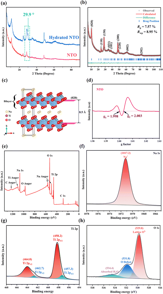
Hydrated NTO was synthesized via a facile solvothermal method,25 and NTO was obtained upon annealing hydrated NTO at 200 °C for 2 h. Preparation details are provided in Sections S1.1 and S1.2 in the ESI.†As shown in Fig. 1a, the XRD patterns of NTO and hydrated NTO are similar with an interlayer spacing of ∼8.5 Å except the disappearance of a weak shoulder peak at 29.9° (d = 3.0 Å) after dehydration, indicating that the low-temperature sintering can remove the absorbed and crystal water of hydrated NTO without the collapse of the framework.
The molar ratio of Na/Ti in NTO was determined to be 0.75![[thin space (1/6-em)]](https://www.rsc.org/images/entities/char_2009.gif) :
:![[thin space (1/6-em)]](https://www.rsc.org/images/entities/char_2009.gif) 1 by inductively coupled plasma emission spectroscopy (ICP), suggesting that the content of Na is high, which is similar to the (Cs + Mg)/Ti molar ratio in Cs0.70(Mg0.35Ti1.65)O4 (ICSD No. 36092). Meanwhile, the XRD profiles of NTO and Cs0.70(Mg0.35Ti1.65)O4 are similar (Fig. S1†); therefore, Rietveld refinement of NTO was conducted using Cs0.70(Mg0.35Ti1.65)O4 as the original model. As shown in Fig. 1b, the calculated diffraction peaks of Na0.98Ti1.3O3 (NTO) agree with its experimental ones (Rp = 7.57% and Rwp = 8.95%), suggesting that NTO (CSD No. 2304602) crystallizes in the orthogonal Imm2 space group, and its cell parameters are calculated to be a = 3.805 (3) Å, b = 16.987 (4) Å, c = 3.023 (2) Å, α = β = γ = 90° and V = 195.39 Å3.
1 by inductively coupled plasma emission spectroscopy (ICP), suggesting that the content of Na is high, which is similar to the (Cs + Mg)/Ti molar ratio in Cs0.70(Mg0.35Ti1.65)O4 (ICSD No. 36092). Meanwhile, the XRD profiles of NTO and Cs0.70(Mg0.35Ti1.65)O4 are similar (Fig. S1†); therefore, Rietveld refinement of NTO was conducted using Cs0.70(Mg0.35Ti1.65)O4 as the original model. As shown in Fig. 1b, the calculated diffraction peaks of Na0.98Ti1.3O3 (NTO) agree with its experimental ones (Rp = 7.57% and Rwp = 8.95%), suggesting that NTO (CSD No. 2304602) crystallizes in the orthogonal Imm2 space group, and its cell parameters are calculated to be a = 3.805 (3) Å, b = 16.987 (4) Å, c = 3.023 (2) Å, α = β = γ = 90° and V = 195.39 Å3.
As shown in Fig. 1c, NTO displays a 2D layered framework, and Na+ ions occupy the interlayer channel. The Ti center in NTO is coordinated with six oxygen atoms to furnish a slightly distorted {TiO6} octahedron (Ti⋯O distance: 1.877–2.260 Å), and the neighboring {TiO6} octahedra are linked into the 2D Ti–O–Ti layer via sharing edges and vertices. The Na⋯O distances (2.940–3.373 Å) are slightly long for a covalent bond, indicating that the interactions between the lamellar Na+ and Ti–O–Ti layers are weak, which is beneficial for Na+ migration in the 2D interlayer channel. And Na+ can migrate along the 2D ac-plane (the ac-diagonal ([101]) direction). Therefore, it is predicted that NTO could be a potential sodium ion conductor and used as a solid-state electrolyte for SIBs. It is worth mentioning that some oxygen atoms of the Ti–O–Ti layer are partially occupied, indicating the presence of abundant oxygen vacancies in the structure, which is proved by electron paramagnetic resonance (EPR) of NTO. As shown in Fig. 1d, the EPR signal (g1 = 1.998) comes from Ti3+,26–28 and the EPR signal (g2 = 2.003) is attributed to the electrons captured at the oxygen vacancies.28,29 And it is estimated that the rich vacancies are beneficial for Na+ migration in the inner channel.30 The electronic conductivity of NTO was also measured, and was determined to be 5.95 × 10⁻⁵ S cm−1 by the four-contact probe method at room temperature. The low electron conductivity of NTO suggests that NTO is a good candidate in the field of SSEs.
The content of water in hydrated NTO can be evaluated by TG analysis, indicating that the sample exhibits good affinity for water molecules (please see Section S2 and Fig. S2a in the ESI† for details). And the Raman spectrum of hydrated NTO is discernibly different from that of commercial TiO2, indicating that they possess completely different frameworks (Fig. S2b†).
The composition of hydrated NTO can be further confirmed by X-ray photoelectron spectroscopy (XPS). Fig. 1e shows the survey spectrum, where the appearance of Na, Ti and O signals is consistent with the elemental composition of hydrated NTO, in which the molar ratio of Na/Ti on the surface is 0.80![[thin space (1/6-em)]](https://www.rsc.org/images/entities/char_2009.gif) :
:![[thin space (1/6-em)]](https://www.rsc.org/images/entities/char_2009.gif) 1 (Fig. 1e), which is similar to the ICP result of NTO (0.76
1 (Fig. 1e), which is similar to the ICP result of NTO (0.76![[thin space (1/6-em)]](https://www.rsc.org/images/entities/char_2009.gif) :
:![[thin space (1/6-em)]](https://www.rsc.org/images/entities/char_2009.gif) 1). The Na 1s spectrum shows the signal of Na+ at ∼1017.2 eV (Fig. 1f).31 In the Ti 2p fine spectrum, the peaks at ∼458.2 and 464.0 eV correspond to Ti 2p3/2 and Ti 2p1/2 of Ti4+, respectively, and the weak peaks at ∼457.3 and 462.7 eV belong to Ti 2p3/2 and Ti 2p1/2 of Ti3+ (Fig. 1g), and the molar ratio of Ti4+/Ti3+ is ca. 6.5
1). The Na 1s spectrum shows the signal of Na+ at ∼1017.2 eV (Fig. 1f).31 In the Ti 2p fine spectrum, the peaks at ∼458.2 and 464.0 eV correspond to Ti 2p3/2 and Ti 2p1/2 of Ti4+, respectively, and the weak peaks at ∼457.3 and 462.7 eV belong to Ti 2p3/2 and Ti 2p1/2 of Ti3+ (Fig. 1g), and the molar ratio of Ti4+/Ti3+ is ca. 6.5![[thin space (1/6-em)]](https://www.rsc.org/images/entities/char_2009.gif) :
:![[thin space (1/6-em)]](https://www.rsc.org/images/entities/char_2009.gif) 1.32 And the fine spectrum of O 1s can be deconvoluted into lattice O2− (Ti–O bond, ∼529.8 eV), oxygen defects (∼531.8 eV) and adsorbed water (∼534.4 eV) (Fig. 1h).33,34 The presence of Ti3+ and oxygen defects/vacancies is consistent with EPR results.
1.32 And the fine spectrum of O 1s can be deconvoluted into lattice O2− (Ti–O bond, ∼529.8 eV), oxygen defects (∼531.8 eV) and adsorbed water (∼534.4 eV) (Fig. 1h).33,34 The presence of Ti3+ and oxygen defects/vacancies is consistent with EPR results.
The morphologies of the sample before and after sintering were characterized by scanning electron microscopy (SEM). As shown in Fig. 2(a, b) and S3(a, b),† hydrated NTO and NTO both exhibit a needle-like morphology and these needles aggregate together into clusters, indicating the maintenance of the morphology during the sintering process. And energy-dispersive spectroscopy (EDS) unveils that the Na/Ti molar ratio in the NTO needles is similar to the ICP data (Fig. S3c†). Since solvent should be used for the fabrication of a composite polymer solid-state electrolyte (CPE), in order to investigate whether the morphology of NTO is related to the solvent, NTO was recrystallized from N,N′-dimethylformamide (DMF) or N-methyl-2-pyrrolidone (NMP) (Section S1.3 in the ESI†), and the recrystallized samples were denoted as NTO-DMF and NTO-NMP, respectively. These recrystallized NTO samples all exhibit a sheet-like morphology, and these sheets are stacked together (Fig. 2c and d). Impressively, when NTO-DMF was immersed in water again (denoted as NTO-DMF-water), the needle-like morphology recovers again (Fig. 2e), suggesting the morphological change is reversible.
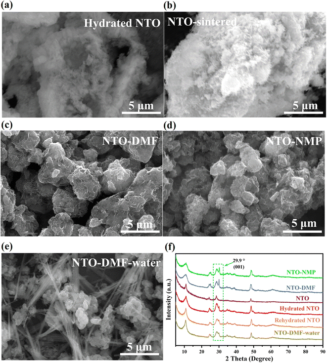 | ||
| Fig. 2 (a–e) SEM images and (f) XRD patterns of (a) hydrated NTO, (b) NTO, (c) NTO-DMF, (d) NTO-NMP and (e) NTO-DMF-water. | ||
In order to reveal the reason for the interesting morphology, XRD characterization was performed on the samples. As shown in Fig. 2f, all the samples show similar XRD patterns. Their main difference is the (001) diffraction peak at ∼29.9° (d = 3.0 Å), which disappears after dehydration but appears with significantly increased relative intensity after recrystallization in DMF or NMP, suggesting that these solvents can induce the emergence of the (001) crystalline plane of NTO. As shown in Fig. S4,† viewed along the a-axis ([100] direction), when the lattice fringe of the (001) facet is observed, the interlayer channel of NTO and its (101) facet are exposed, which is conducive to the migration of Na+ along the ac-diagonal ([101]) direction (the ac-plane) in the interlayer channel of NTO. As shown in Fig. 2f, when NTO or NTO-DMF was immersed in water again or exposure to humid air, the XRD patterns of the rehydrated NTO and NTO-DMF-water are the same as that of hydrated NTO with the decreased relative intensity of the (001) peak, further proving the good affinity of the sample for water, which can also explain the re-occurrence of the needle-like morphology in NTO-DMF-water (Fig. 2e).
The NTO microneedle and microsheet were characterized by transmission electron microscopy (TEM), high resolution transmission electron microscopy (HRTEM), and selected area electron diffraction (SAED). As shown in Fig. 3(a and b), Na, Ti and O elements are uniformly distributed on the surfaces of the NTO microneedle and microsheet. And EDS demonstrates that they possess similar elemental composition (Fig. 3c), in which the Na/Ti molar ratio agrees with the ICP result if deducting the instrumental error.
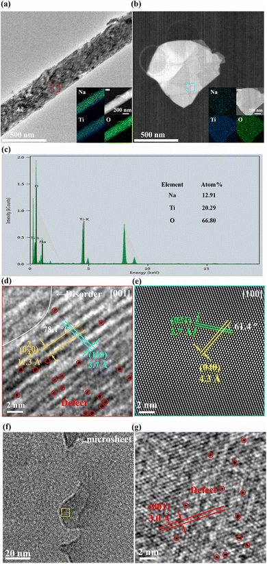 | ||
| Fig. 3 (a, b and f) TEM (inset: elemental mappings), (c) EDS and (d, e and g) HRTEM of (a and d) an NTO microneedle and (b and e–g) microsheet. | ||
The HRTEM image of the NTO microneedle (Fig. 3a, marked by a red square) shows the lattice fringes of ∼11.3 and 3.7 Å with a dihedral angle of about 78.1°, which corresponds to the (0 2/3 0) and (110) crystalline planes of NTO, respectively (Fig. 3d), suggesting that the zone axis is along the [001] direction. And a large number of defects and disorders are observed in the microneedle (Fig. 3d), which is probably associated with the intercalation of Na+ into the lamellar channel.17
In contrast, the HAADF-STEM of the NTO microsheet (Fig. 3b, marked by a blue square) shows d spacings of ∼4.3 Å and 2.7 Å with a dihedral angle of about 61.4°, which are attributed to the (040) and (031) planes of NTO, respectively (Fig. 3e), indicating that the zone axis is along the [001] direction. Meanwhile, viewed along the [100] direction, a lattice fringe of 3.0 Å is also observed on the periphery of the microsheet (Fig. 3f, marked by a yellow square), corresponding to the (001) facet (Fig. 3g), which is also observed in the XRD patterns of NTO sheets (Fig. 1a). Therefore, the microneedle- and microsheet-like morphologies of NTO are ascribed to their different exposed facets. The SAED patterns of the NTO microneedle (Fig. S5a†) and microsheet (Fig. S5b†) also agree with the HRTEM results (Section S3 in the ESI†).
2.2 Structure and morphology of NTO CPE
NTO CPE was fabricated based on PVDF-HFP, NaPF6, NTO and DMF in a weight ratio of 30![[thin space (1/6-em)]](https://www.rsc.org/images/entities/char_2009.gif) :
:![[thin space (1/6-em)]](https://www.rsc.org/images/entities/char_2009.gif) 6
6![[thin space (1/6-em)]](https://www.rsc.org/images/entities/char_2009.gif) :
:![[thin space (1/6-em)]](https://www.rsc.org/images/entities/char_2009.gif) 14
14![[thin space (1/6-em)]](https://www.rsc.org/images/entities/char_2009.gif) :
:![[thin space (1/6-em)]](https://www.rsc.org/images/entities/char_2009.gif) 50 (Section S1.4 in the ESI†). The same method was used to prepare the blank SSE except in the absence of NTO.
50 (Section S1.4 in the ESI†). The same method was used to prepare the blank SSE except in the absence of NTO.
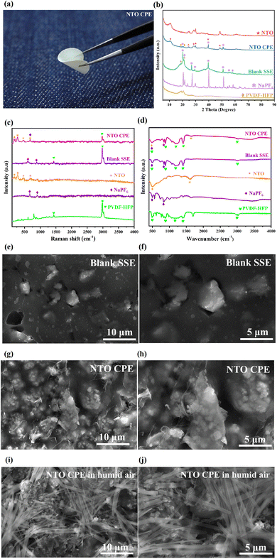
As illustrated in Fig. 4a, NTO CPE can endure a 180° bending without any breakage, suggesting the excellent mechanical flexibility of the obtained CPE film. Fig. 4b shows the XRD patterns of NTO, NTO CPE, blank SSE, NaPF6 and PVDF-HFP. It is worth mentioning that the main diffraction peaks (18–23°) of PVDF-HFP in pure polymer and blank SSE become very weak in NTO CPE, indicating the disappearance of polymer crystallinity in NTO CPE. This amorphous characteristic of the polymer can facilitate ion transport in the polymer matrix.24 Meanwhile, the sharp peaks of NaPF6 in the individual salt and blank SSE vanish in NTO CPE, manifesting that the addition of NTO can decrease the crystallinity of NaPF6. This is probably associated with the rich oxygen vacancies in NTO, which can capture the PF6− and thus promote the dissociation of the cation–anion pairs. In addition, the NTO component in the NTO CPE also exhibits a lowered crystallinity, which is beneficial for the migration of Na+ in the vacancies/defects of NTO and enhances the electrochemical performance.
The phenomenon is also observed in Raman spectra and infrared spectroscopy (IR) spectra. As shown in Fig. 4c, NTO shows obvious Raman peaks at 143, 276, 458 and 638 cm−1, in which the strongest Raman peak at 276 cm−1 corresponds to the bending vibration of O–Ti–O atoms,35 and the peaks at 458 and 638 cm−1 are ascribed to the anti-symmetric in-plane stretching vibrations of Ti–O atoms.35 The vibration signals of NaPF6 are detected at 635 and 901 cm−1. And the strongest Raman peak of PVDF-HFP appears at 2981 cm−1. The Raman peaks of the individual components are observed in NTO CPE. However, the vibration signals of NaPF6 and PVDF-HFP in NTO CPE are significantly weakened, suggesting the decreased vibration intensities of the individual components in NTO CPE due to the interactions between them, which can decrease their crystallinity in NTO CPE and promote Na+ migration along PVDF-HFP. Furthermore, the strongest Raman peak of NaPF6 (635 cm−1) is overlapped with that of NTO (638 cm−1), suggesting the vibration coupling between NaPF6 and NTO, which can probably promote the dissociation of Na+ and PF6− in NaPF6. Similarly, the Raman signals of the individual NaPF6 and PVDF-HFP can be detected in the blank SSE with a slight blue shift in comparison with those of NaPF6.
Further insight can be obtained by virtue of IR spectra. As shown in Fig. 4d, NTO exhibits IR peaks at 485 and 1604 cm−1, corresponding to the vibrations of O–Ti–O.35 And NaPF6 displays IR peaks at 485 and 828 cm−1. These peaks can be detected in the IR spectra of NTO CPE but with obviously decreased intensity, further indicating the interactions between them in NTO CPE. As for PVDF-HFP, it presents IR peaks at 485, 878, 1180, 1403 and 3009 cm−1, which can be observed in NTO CPE and blank SSE. And the peak of NaPF6 at 485 cm−1 is overlapped with those of NTO and PVDF-HFP (485 cm−1), further suggesting the peak couplings between them.
The morphology of blank SSE is shown in Fig. 4(e and f). It can be observed that in blank SSE, bulk NaPF6 particles with different sizes are distributed in a disorderly manner in the PVDF-HFP matrix. In contrast, NaPF6 grains in NTO CPE are uniformly encapsulated by the NTO microsheets and PVDF-HFP matrix (Fig. 4g and h). In addition, the NTO microsheets in NTO CPE are uniformly distributed in the PVDF-HFP matrix (Fig. 4g and h), which is further evidenced by EDS and elemental mappings of NTO CPE (Fig. S6†). As a result, it avoids local high or low concentration of NTO, and Na+ can be transferred in the entire composite solid-state electrolyte membrane, thereby improving the electrochemical stability of the battery. Notably, since DMF was used as the solvent for the fabrication of NTO CPE, NTO shows a microsheet-like morphology in NTO CPE. However, due to the good affinity of NTO for water, the fabrication of NTO CPE should be in the absence of humid air. Otherwise, NTO needles can reappear in the NTO CPE (Fig. 4i and j). Though NTO CPE can be further dried in a vacuum oven to remove the small amount of water, the needle-like morphology of NTO can be maintained after dehydration (Fig. 2a and b).
2.3 Electrochemical performance of NTO CPE
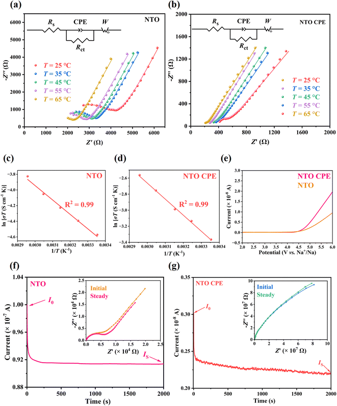
Electrochemical AC impedance spectroscopy (EIS) was used to determine the ionic conductivity (σ) of pure NTO and NTO CPE. Herein, a certain amount of NTO microsheets were cold-pressed into a tablet for the measurement of σ and ion migration activation energy (Ea) of pure NTO (Section S1.4†).Fig. 5a and b show the Nyquist plots of pure NTO and NTO CPE in the temperature range of 25–65 °C, respectively. All data were analyzed using the equivalent circuit of a resistor element (Rs), a parallel combination of charge transfer impedance (Rct) and constant phase element (CPE), and Warburg impedance (W) in series (Fig. 5a and b, inset). The σ of NTO and NTO CPE at room temperature of 25 °C is calculated to be 1.93 × 10⁻⁵ and 1.16 × 10⁻⁴ S cm−1, respectively. The Ea can be deduced from the Arrhenius equation. According to the linear fitting of the plots in Fig. 5(c and d), the Ea of NTO and NTO CPE are calculated to be 0.159 and 0.172 eV, respectively. The small Ea in NTO (0.159 eV) suggests a low energy barrier, which is due to the weak interactions between the lamellar Na+ ions and Ti–O–Ti layers (Na⋯O distances: 2.940–3.373 Å), further illustrating our expectation that the interlayer 2D channel in NTO is beneficial for Na+ transport. NTO CPE shows a much higher conductivity of 1.16 × 10⁻⁴ S cm−1 than the individual NTO. This is perhaps associated with the intrinsic oxygen vacancies in NTO, which can capture the PF6− anions and accelerate the dissociation of Na+–PF6− pairs in the CPE. Meanwhile, the lowered crystallinities of PVDF-HFP, NTO and NaPF6 in the CPE can facilitate Na+ diffusion in the entire CPE.24 Moreover, an interface may be formed between the amorphous polymer matrix and the active filler of NTO, which provides a rapid conduction pathway.36,37
The electrochemical stability windows of NTO and NTO CPE were evaluated using the linear scanning voltammetry (LSV) method in the range of 2–6 V with a scan rate of 1 mV s−1. No oxidation current was observed up to 4.5 V (Fig. 5e), indicating that NTO and NTO CPE are electrochemically stable towards Na with a wide electrochemical window of 4.5 V. After the voltage exceeds 4.5 V, the oxidation rate of NTO CPE is faster than that of NTO, which may be due to the oxidation decomposition of the organic components in the CPE, giving rise to a very weak oxidation current in the magnitude of 10−8 A. The thermal stability of PVDF-HFP was explored by TG analysis. As shown in Fig. S7,† no weight loss was observed up to 420 °C, indicating a good thermal stability of PVDF-HFP. In contrast, NaPF6 presents a continuous weight loss from room temperature to 700 °C (Fig. S7†), which is probably related with its good affinity for water.
By a direct-current (DC) polarization test, the Na+ transference number (tNa+) of NTO was measured to be 0.91 (Fig. 5f). The value is close to 1, which is associated with the stable anionic host framework of NTO. When Na+ ions migrate along the interlayer channel of NTO, its anionic Ti–O–Ti layer is almost fixed. As a result, NTO behaves like a single ion conductor with almost net cation transport, which can make up for its lower ionic conductivity (1.93 × 10⁻⁵ S cm−1) when used in a solid-state battery. After combination with PVDF-HFP, the obtained NTO CPE shows a Na+ transference number of 0.73 (Fig. 5g), which is slightly lower than that of pure NTO. However, it is still two or three times higher than that of organic liquid electrolytes (normally from 0.2 to 0.3).
The electrochemical cycling performance of pure NTO was measured with the symmetric Na|NTO|Na cell at 0.2 mA cm−2, and the cell was intermittently charged and discharged for 1 h in each cycle. It should be mentioned that the pure NTO was microsheet-like NTO, which was obtained by recrystallization from DMF. The Na–Na symmetric cell built by needle-like NTO doesn't work at all during the whole charge/discharge process, suggesting a broken and disconnected circuit for the cell (Fig. S8a†). In contrast, in the presence of microsheet-like NTO, the cell can operate stably in the initial charge/discharge cycles with an overpotential of ∼0.4 V (Fig. S8b†). The lower overpotential indicates an even Na+ flux at the Na/NTO, which is due to the matched lattices of Na and sheet-like NTO. As mentioned above, in the sheet-like NTO, its (001) facet is exposed (Fig. 1a). And as we know, the strongest facet of Na (ICSD No. 44757) is the (110) one, which matches with the (001) exposed facet of the sheet-like NTO, d(110) (Na) = d(001) (NTO) = 0.30 nm, leading to the successful (de)intercalation of Na+ (from)into the inner channel of NTO. After several discharge/charge cycles, there is an obvious sharp drop in overpotential, indicating the formation of an internal microshort-circuit due to the formation of Na dendrites. This is mainly associated with the microcracks within NTO powder, which provide space for the growth of Na dendrites during the continuous Na stripping/plating process.
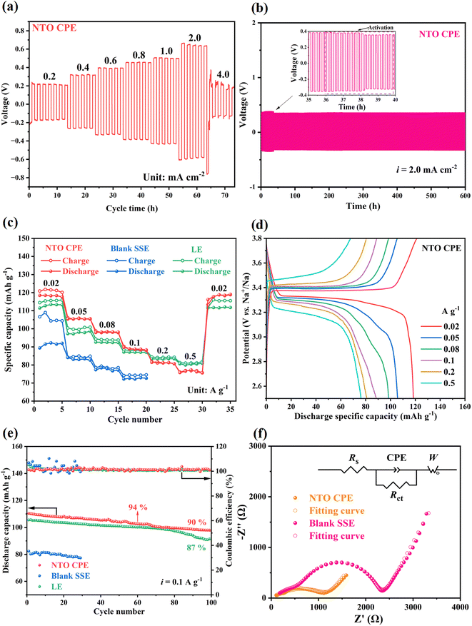
The poor flexibility of inorganic NTO electrolyte can be compensated for by combination with an organic PVDF-HFP polymer. And the tolerance of NTO CPE to Na dendrites was firstly evaluated by the critical current density (CCD) measurement of the Na|NTO CPE|Na cell. The test was performed with stepped current densities from 0.2 mA cm−2 to 4 mA cm−2. As shown in Fig. 6a, when the current density was increased to 4 mA cm−2, the voltage gap between charge and discharge began to decrease sharply, suggesting that the critical current density can reach 4.0 mA cm−2. It is higher than those reported previously,38,39 which is attributed to the reduced NTO powder boundaries in the presence of flexible PVDF-HFP polymer. And the homogeneous interfaces and interactions between each component achieve good interfacial compatibility (Fig. 4e and f). The Na|NTO CPE|Na symmetric cell further shows a stable voltage-response profile throughout 3000 continuous charge–discharge cycles at 2.0 mA cm−2/0.2 mA h cm−2 (600 h) (Fig. 6b), depicting that NTO CPE can effectively suppress the formation/growth of Na dendrites. Besides, from the voltage profile of the Na stripping and plating (Fig. 6b, inset), the voltage slightly decreases from about 0.38 V to ∼0.32 V at around 38 h and then stays stable, which could be attributed to the interface activation process.40,41 This is probably due to the increase of specific contact area of the interface and the decrease of real electrolyte thickness resulting from Na penetration into the voids of NTO CPE.40,41 In order to prove the expectation, the NTO CPE over 30 h- and 40 h-cycling tests of the Na|NTO CPE|Na symmetric cell was characterized by EIS. As shown in Fig. S9,† the 40 h-sample shows a smaller charge-transfer impedance (Rct) than the 30 h-sample. Similarly, it is worth noting that the NTO CPE should be prepared in the absence of humid air due to the good affinity of NTO for water. Otherwise, needle-like NTO can regenerate and maintain in NTO CPE even after further dehydration (Fig. 4g and h), which indicates the (001) facet of NTO is no longer the exposed facet (Fig. 1a). As a result, the Na|NTO CPE|Na symmetric cell also cannot work, which presents a disconnected circuit, further verifying the significance of the lattice-matched Na/NTO interface.
To assess the electrochemical properties of sodium metal batteries, Na|electrolyte|Na3V2(PO4)3 (NVP) full cells were assembled using NTO CPE, blank SSE, and liquid electrolyte (LE, 1 M NaPF6 in diglyme), respectively. As shown in Fig. 6c, the Na|NTO CPE|NVP full cell exhibits an excellent rate capability, which delivers high discharge specific capacities of ∼118, 105, 98, 89, 81 and 75 mA h g−1 at current densities of 0.02, 0.05, 0.08, 0.1, 0.2 and 0.5 A g−1, respectively. And after five cycles at each current density, the discharge capacity recovers to ∼118 mA h g−1 when the current density returns to 0.02 A g−1. The corresponding charge–discharge curves of the Na|NTO CPE|NVP battery ranging from 0.02 to 0.5 A g−1 are presented in Fig. 6d, and it can be observed that there is less voltage polarization. The excellent rate performance is mainly attributed to good interfacial compatibility and excellent ionic conductivity of NTO CPE. Furthermore, higher capacities are obtained in the presence of NTO CPE at lower current density (0.02–0.1 A g−1) compared with a liquid battery using commercial NaPF6 electrolyte (Fig. 6d), which is associated with the higher Na+ transport number in NTO CPE. Meanwhile, it is predicted that the redox-active Ti in NTO can provide extra capacity. In order to prove the expectation, NTO was utilized as a cathode for the fabrication of the Na|LE|NTO cell to explore the redox activity of NTO (details are demonstrated in Section S4 and Fig. S10 in the ESI†).
Afterwards, the cycling performances of the Na|NTO CPE|NVP and Na|LE|NVP full cells were comparatively measured at 0.1 A g−1. In the presence of NTO CPE, the discharge capacity is basically retained after 60/100 cycles (retention: 94/90%) (Fig. 6e), which is superior to that in the presence of LE (retention: 87% over 100 cycles), indicating the excellent structural stability of NTO.
For comparison, a Na|blank SSE|NVP full battery was also assembled, and it exhibited a far inferior rate capability and cycling behavior (details are presented in Section S5 in the ESI†). The result further demonstrates that the presence of NTO can not only improve the Na+ transport along the amorphous PVDF-HFP polymer chain, but also provide an interlayer channel for Na+ migration in NTO, thus enhancing the electrochemical performance of the overall battery. The conclusion is also evidenced by EIS spectra of the Na|NTO CPE|NVP and Na|blank SSE|NVP cells. As shown in Fig. 6f, Na|NTO CPE|NVP displays a lower series resistance (Rs) and a lower charge-transfer impedance (Rct) than Na|blank SSE|NVP.
2.4 Compositions and morphologies of NTO CPE and Na metal after the cycling test
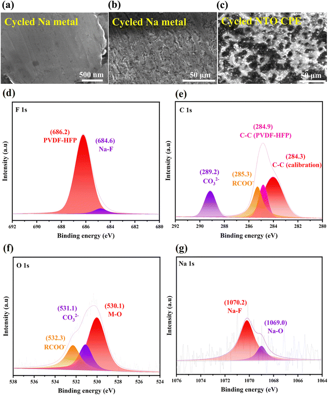
In order to explore the morphology and composition of the Na/NTO CPE interface, the cycled Na|NTO CPE|Na symmetric cell was disassembled. The SEM images of the cycled Na metal are shown in Fig. 7a and b, in which the surface of Na metal still remains flat and uniform. EDS reveals that the surface is covered by large amounts of Na, F, O and C elements (Fig. S11a†), indicating that the SEI layer is mainly composed of sodium fluoride, sodium carboxylate and carbonate. The matched lattice spacing of Na and NTO leads to stable cycling behavior of the symmetric cell, especially in the initial cycles. And the continuous uniform Na+ deposition/exfoliation at the interface is associated with the flexible PVDF-HFP organic polymer in NTO CPE, which can evenly fill in the voids between NTO sheets, resulting in smooth NTO/Na interfacial contact to form a continuous Na-ion transport pathway and alleviate Na dendrite formation/growth.The cycled NTO CPE was also characterized by SEM. As shown in Fig. 7c, the surface of the cycled NTO CPE is coated by an SEI layer, which is built from homogeneously distributed nanoparticles (NPs). EDS as well as elemental mappings reveal that the main elements of the SEI layer are Na, F, O and C (Fig. S11b†), in agreement with the superficial composition of the cycled Na metal (Fig. S11a†). The result further demonstrates that the PVDF-HFP organic polymer in NTO CPE can bridge the interstices between NTO powder and change interfacial point contact into surface contact with Na metal, thus accelerating the interfacial Na+ flux transport.
In order to further investigate the chemical valences of the elements in the SEI layer, the cycled NTO CPE was inspected by XPS. The F 1s fine spectrum can be deconvoluted into PVDF-HFP (686.2 eV) and Na–F (684.6 eV) (Fig. 7d),42 indicating the formation of NaF in the SEI layer.
In the C 1s fine spectrum (Fig. 7e), the peaks at 284.9 and 284.3 eV come from PVDF-HFP and the standard carbon for calibration, respectively. And the peaks at 285.3 and 289.2 eV are attributed to RCOO− and CO32−, respectively,43 further suggesting the presence of organic carboxylate and sodium carbonate in the SEI layer. The result is also proved by the O 1s spectrum. As shown in Fig. 7f, the O 1s signals are divided into RCOO− (532.3 eV), CO32− (531.1 eV) and lattice M–O (Ti–O, 530.1 eV).44 And the Na 1s spectrum can be split into Na–F (1070.2 eV) and Na–O (1069.0 eV) (Fig. 7g),31,45 which is due to the formation of Na–F, sodium carboxylate or carbonate in the SEI layer, and NaF is the dominant component.
2.5 DFT simulation
The Na+ diffusion kinetics in the interlayer channel of NTO was calculated using the climbing-image nudged elastic band (CI-NEB) method.46Fig. 8a show the Na+ migration paths along the 2D ac-plane (the ac-diagonal ([101]) direction). In Fig. 8b, the corresponding Na+ migration barrier is 0.198 eV, which is relatively close to the experimentally measured activation energy of Na+ migration in NTO (0.159 eV), further manifesting that NTO is an excellent Na+ conductor which can be used as a solid-state electrolyte. And the calculated energy barrier is close to those in the Na-ion conductors such as β-Al2O3, layered Na2Ti3O7 and NaxVOPO4.47–49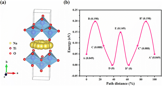 | ||
| Fig. 8 Na+ migration paths in the interlayer channel of NTO along (a) the ac-diagonal direction with (b) corresponding energy barrier. | ||
3 Conclusion
In summary, a needle-like hydrated layered sodium titanate (hydrated NTO) was synthesized using a simple one-step solvothermal method. Upon low-temperature annealing, the dehydrated sample, Na0.98Ti1.3O3 (NTO), with abundant oxygen vacancies was obtained and then characterized by Rietveld refinement, HAADF-STEM and EPR. After recrystallization in DMF or NMP, the (001) facet of NTO is exposed and its morphology transforms from needles into sheets. A low ion migration Ea of ∼0.159 eV is observed in the sheet-like NTO with a high tNa+ of 0.91, as evidenced by DFT calculations, which is due to the weak interactions between the lamellar Na+ ions and unmoved anionic Ti–O–Ti layers, indicating that NTO behaves like a single ion conductor. An NTO CPE was prepared from PVDF-HFP, sheet-like NTO and NaPF6, and it exhibited a high σ of 1.16 × 10⁻⁴ S cm−1 with a tNa+ of 0.73. The Na|NTO|Na symmetric cell can work normally in the initial cycles and the Na|NTO CPE|Na cell can undergo 3000 continuous Na stripping/plating cycles at 2 mA cm−2, which is associated with the matched lattice of the Na (110) and NTO (001) facets, d(110) (Na) = d(001) (NTO) = 0.30 nm. Moreover, the Na|NTO CPE|NVP full battery shows a high reversible discharge specific capacity of approximately 118 mA h g−1 at a current density of 0.02 A g−1. After 100 charge/discharge cycles at 0.1 A g−1, the capacity retention can reach 90%, indicative of excellent cycling stability, which is better than that of the cells in liquid electrolyte and the blank SSE in the absence of NTO. This is expected to be associated with the intrinsic oxygen vacancies in NTO, which can capture PF6− and promote the dissociation of cation–anion pairs. Meanwhile, the interactions between PVDF-HFP, NTO and NaPF6 lead to the decreased crystallinity of each component in NTO CPE, thus promoting the migration of Na+ in NTO and along the amorphous PVDF-HFP polymer chain.Data availability
The data that supports the findings of this work is available from the corresponding author upon reasonable request.Author contributions
Xuanao Ma: data curation, formal analysis, investigation, methodology and writing. Yang Liu: data curation, formal analysis, investigation and methodology. Yunhuai Zhang: project administration. Yun Gong: conceptualization, funding acquisition, methodology, project administration, resources, software, supervision and writing.Conflicts of interest
There are no conflicts to declare.Acknowledgements
Financial support from the National Natural Science Foundation of China (No. 22171030 and 21771028), National-Municipal Joint Engineering Laboratory for Chemical Process Intensification and Reaction, and Chongqing Key Laboratory of Chemical Process for Clean Energy and Resource Utilization is gratefully acknowledged.References
- Z. Zeng, V. Murugesan, K. S. Han, X. Jiang, Y. Cao, L. Xiao, X. Ai, H. Yang, J.-G. Zhang, M. L. Sushko and J. Liu, Nat. Energy, 2018, 3, 674–681 CrossRef CAS.
- B. Tong, Z. Y. Song, W. F. Feng, J. Zhu, H. L. Yu, X. J. Huang, M. Armand, Z. B. Zhou and H. Zhang, Adv. Energy Mater., 2023, 13, 2204085 CrossRef CAS.
- Q. Zhao, S. Stalin, C.-Z. Zhao and L. A. Archer, Nat. Rev. Mater., 2020, 5, 229–252 CrossRef CAS.
- X. B. Cheng, R. Zhang, C. Z. Zhao and Q. Zhang, Chem. Rev., 2017, 117, 10403–10473 CrossRef CAS PubMed.
- H. L. Pan, Y. S. Hu and L. Q. Chen, Energy Environ. Sci., 2013, 6, 2338–2360 RSC.
- Q. Yi, Y. Lu, X. Sun, H. Zhang, H. Yu and C. Sun, ACS Appl. Mater. Interfaces, 2019, 11, 46965–46972 CrossRef CAS PubMed.
- Y. Lu, L. Lu, G. Qiu and C. Sun, ACS Appl. Mater. Interfaces, 2020, 12, 39342–39351 CrossRef CAS PubMed.
- Q. Yi, W. Zhang, S. Li, X. Li and C. Sun, ACS Appl. Mater. Interfaces, 2018, 10, 35039–35046 CrossRef CAS PubMed.
- L. Lu, C. Sun, J. Hao, Z. Wang, S. F. Mayer, M. T. Fernandez-Diaz, J. A. Alonso and B. Zou, Energy Environ. Mater., 2023, 6, e12364 CrossRef CAS.
- L. Lu, Y. Lu, J. Antonio Alonso, C. Alberto Lopez, M. Teresa Fernandez-Diaz, B. Zou and C. Sun, ACS Appl. Mater. Interfaces, 2021, 13, 42927–42934 CrossRef CAS PubMed.
- W. D. Richards, L. J. Miara, Y. Wang, J. C. Kim and G. Ceder, Chem. Mater., 2016, 28, 266–273 CrossRef CAS.
- Q. L. Ma, M. Guin, S. Naqash, C. L. Tsai, F. Tietz and O. Guillon, Chem. Mater., 2016, 28, 4821–4828 CrossRef CAS.
- H. Kwak, J. Lyoo, J. Park, Y. Han, R. Asakura, A. Remhof, C. Battaglia, H. Kim, S. T. Hong and Y. S. Jung, Energy Storage Mater., 2021, 37, 47–54 CrossRef.
- J. Park, J. P. Son, W. S. Ko, J. S. Kim, Y. Choi, H. Kim, H. Kwak, D. H. Seo, J. Kim and Y. S. Jung, ACS Energy Lett., 2022, 7, 3293–3301 CrossRef CAS.
- H. Xia, X. H. Zhu, J. Z. Liu, Q. Liu, S. Lan, Q. H. Zhang, X. Y. Liu, J. K. Seo, T. T. Chen, L. Gu and Y. S. Meng, Nat. Commun., 2018, 9, 5100 CrossRef PubMed.
- N. B. Liu, X. Y. Zhao, B. Qin, D. D. Zhao, H. H. Dong, M. D. Qiu and L. B. Wang, J. Mater. Chem. A, 2022, 10, 25168–25177 RSC.
- R. Tang, K. Li, C. Liu, Y. Liu, Y. Gong and J. Lin, Chem. Eng. J., 2023, 453, 139734 CrossRef CAS.
- K. Y. Tao, Y. Gong and J. H. Lin, Nano Energy, 2019, 55, 65–81 CrossRef CAS.
- J. Pan, Y. C. Zhang, F. Sun, M. Osenberg, A. Hilger, I. Manke, R. G. Cao, S. X. Dou and H. J. Fan, Angew. Chem., Int. Ed., 2023, 62, e202219000 CrossRef CAS PubMed.
- J. M. Zhang, Y. P. Zeng, Q. P. Li, Z. Tang, D. Sun, D. Huang, L. Zhao, Y. G. Tang and H. Y. Wang, Energy Storage Mater., 2023, 54, 440–449 CrossRef.
- J. H. Wang, Y. Yamada, K. Sodeyama, E. Watanabe, K. Takada, Y. Tateyama and A. Yamada, Nat. Energy, 2018, 3, 22–29 CrossRef CAS.
- X. W. Yu, L. G. Xue, J. B. Goodenough and A. Manthiram, Adv. Funct. Mater., 2021, 31, 2002144 CrossRef CAS.
- T. S. Feng, Y. B. Hu, L. Xu, J. Q. Huang, S. B. Hu, L. F. Zhang and L. L. Luo, Mater. Today Energy, 2022, 28, 101062 CrossRef CAS.
- H. Duan, M. Fan, W. P. Chen, J. Y. Li, P. F. Wang, W. P. Wang, J. L. Shi, Y. X. Yin, L. J. Wan and Y. G. Guo, Adv. Mater., 2019, 31, 1807789 CrossRef PubMed.
- W. Han, H. S. Lee, B. Yoo and H. H. Park, J. Alloys Compd., 2017, 695, 2160–2164 CrossRef CAS.
- D. Widmann, A. Krautsieder, P. Walter, A. Brückner and R. J. Behm, ACS Catal., 2016, 6, 5005–5011 CrossRef CAS.
- J. Strunk, W. C. Vining and A. T. Bell, J. Phys. Chem. C, 2010, 114, 16937–16945 CrossRef CAS.
- M. Fan, Z. Lin, P. Zhang, X. Ma, K. Wu, M. Liu and X. Xiong, Adv. Energy Mater., 2020, 11, 2003037 CrossRef.
- S. L. Zhang, Q. N. Fan, Y. Liu, S. B. Xi, X. F. Liu, Z. B. Wu, J. N. Hao, W. K. Pang, T. F. Zhou and Z. P. Guo, Adv. Mater., 2020, 32, 2000380 CrossRef CAS PubMed.
- J. Mei, T. Wang, D. Qi, J. Liu, T. Liao, Y. Yamauchi and Z. Sun, ACS Nano, 2021, 15, 13604–13615 CrossRef CAS PubMed.
- E. Hosono, H. Matsuda, I. Honma, S. Fujihara, M. Ichihara and H. S. Zhou, J. Power Sources, 2008, 182, 349–352 CrossRef CAS.
- B. Gong, X. Luo, N. Bao, J. Ding, S. Li and J. Yi, Surf. Interface Anal., 2014, 46, 1043–1046 CrossRef CAS.
- H. Liu, J.-G. Wang, Z. You, C. Wei, F. Kang and B. Wei, Mater. Today, 2021, 42, 73–98 CrossRef CAS.
- Q. Tan, X. Li, B. Zhang, X. Chen, Y. Tian, H. Wan, L. Zhang, L. Miao, C. Wang, Y. Gan, J. Jiang, Y. Wang and H. Wang, Adv. Energy Mater., 2020, 10, 2001050 CrossRef CAS.
- Y. Cao, Q. Ye, F. Wang, X. Fan, L. Hu, F. Wang, T. Zhai and H. Li, Adv. Funct. Mater., 2020, 30, 2003733 CrossRef.
- W. Liu, S. W. Lee, D. C. Lin, F. F. Shi, S. Wang, A. D. Sendek and Y. Cui, Nat. Energy, 2017, 2, 17035 CrossRef CAS.
- T. Yang, J. Zheng, Q. Cheng, Y. Y. Hu and C. K. Chan, ACS Appl. Mater. Interfaces, 2017, 9, 21773–21780 CrossRef CAS PubMed.
- X. X. Wang, J. J. Chen, Z. Y. Mao and D. J. Wang, Chem. Eng. J., 2022, 427, 130899 CrossRef CAS.
- X. G. Miao, H. Y. Wang, R. Sun, X. L. Ge, D. Y. Zhao, P. Wang, R. T. Wang and L. W. Yin, Adv. Energy Mater., 2021, 11, 2003469 CrossRef CAS.
- B. Zhao, W. Ma, B. Li, X. Hu, S. Lu, X. Liu, Y. Jiang and J. Zhang, Nano Energy, 2022, 91, 106643 CrossRef CAS.
- J. Liang, X. Li, S. Wang, K. R. Adair, W. Li, Y. Zhao, C. Wang, Y. Hu, L. Zhang, S. Zhao, S. Lu, H. Huang, R. Li, Y. Mo and X. Sun, J. Am. Chem. Soc., 2020, 142, 7012–7022 CrossRef CAS PubMed.
- C. L. Zhu, D. X. Wu, Z. S. Wang, H. P. Wang, J. D. Liu, K. L. Guo, Q. H. Liu and J. M. Ma, Adv. Funct. Mater., 2023, 202214195, DOI:10.1002/adfm.202214195.
- M. Yao, Q. Ruan, Y. Wang, L. Du, Q. Li, L. Xu, R. Wang and H. Zhang, Adv. Funct. Mater., 2023, 33, 2213702 CrossRef CAS.
- S. Kim, Y. Jung, J. Park, M. Hong and H. R. Byon, Bull. Korean Chem. Soc., 2021, 42, 1519–1523 CrossRef CAS.
- S. G. Hengyi Fang, M. Ren, Y. Huang, F. Cheng, J. Chen and F. Li, Angew. Chem., Int. Ed., 2023, 62, e202214717 CrossRef PubMed.
- G. Henkelman and H. Jonsson, J. Chem. Phys., 2000, 113, 9978–9985 CrossRef CAS.
- D. Morgan, A. van der Ven and G. Ceder, Electrochem. Solid-State Lett., 2004, 7, A30–A32 CrossRef CAS.
- H. L. Pan, X. Lu, X. Q. Yu, Y. S. Hu, H. Li, X. Q. Yang and L. Q. Chen, Adv. Energy Mater., 2013, 3, 1186–1194 CrossRef CAS.
- J. Ding, Y. C. Lin, J. Liu, J. Rana, H. L. Zhang, H. Zhou, I. H. Chu, K. M. Wiaderek, F. Omenya, N. A. Chernova, K. W. Chapman, L. F. J. Piper, S. P. Ong and M. S. Whittingham, Adv. Energy Mater., 2018, 8, 1800221 CrossRef.
Footnotes |
| † Electronic supplementary information (ESI) available: Experimental section; TG and Raman analyses; SEM and EDS as well as elemental mappings; SAED analysis; cycling performance of the Na|NTO|Na symmetric cell; redox properties of NTO; rate capability and cycling performance of the Na|blank SSE|NVP full battery; etc. CCDC 2304602. For ESI and crystallographic data in CIF or other electronic format see DOI: https://doi.org/10.1039/d3sc04355j |
| ‡ Xuanao Ma and Yang Liu contributed equally to the work. |
| This journal is © The Royal Society of Chemistry 2023 |

