
A laser-induced graphene-based electrochemical immunosensor for nucleic acid methylation detection†
Jingyi
Guo
,
Mei
Zhao
,
Chen
Chen
,
Fang
Wang
 * and
Zilin
Chen
* and
Zilin
Chen
School of Pharmaceutical Sciences, Key Laboratory of Combinatorial Biosynthesis and Drug Discovery (MOE), Wuhan University, Wuhan, 430071, China. E-mail: fwang@whu.edu.cn
First published on 21st November 2023
Abstract
The detection of methylation in DNA and RNA is essential for the diagnosis and treatment of a wide range of diseases. A one-step fabricated laser-induced graphene (LIG) electrode has received increasing attention due to its good electrical conductivity, large specific surface area, ease of miniaturization, low cost and flexibility. Herein, a potential biosensor for N6-methyladenosine (m6A-RNA) and 5-methylcystosine-single strand DNA (5mC-ssDNA) detection was designed. The aim of this paper is to address the problem of detecting the m6A-RNA and 5mC-ssDNA content in cells. By stepwise modification of gold nanoparticles (AuNPs), sulfhydryl-modified nucleic acid chains, biotin-modified antibodies, and streptavidin-modified horseradish peroxidase (SA-HRP) at the LIG electrode, the peak current responses exhibited an increase proportional to the concentration of m6A-RNA and 5mC-ssDNA in the hydrogen peroxide–hydroquinone (H2O2–HQ) system. This method demonstrated a low detection limit of 2.81 pM for m6A-RNA and 9.53 pM for 5mC-ssDNA, with a linear detection range of 0.01 nM to 10 nM for both targets. The regression equation was determined as ΔI = 4.83![[thin space (1/6-em)]](https://www.rsc.org/images/entities/char_2009.gif) logc + 12.32 (R2 = 0.9980) for m6A-RNA and ΔI = 9.82logc + 22.09 (R2 = 0.9903) for 5mC-ssDNA. Our method has good selectivity toward different detection targets of nucleic acid chains, stability for long-term storage and consecutive scanning (RSD of 9.42% and 2.08%, respectively) and reproducibility of 5 electrodes (RSD of 6.85%). This method utilizes gold–sulfur bonding to immobilize the detection target, which improves the conductivity of the LIG electrode and introduces an amplified portion of the signal by taking advantage of antigen–antibody specific binding. Thus, dual detection of m6A-RNA and 5mC-ssDNA was realized. Importantly, this approach is successfully applied for the detection of targets in spiked samples extracted from HeLa cells, suggesting its potential for clinical applications and providing a new perspective for the development of point-of care testing (POCT) techniques.
logc + 12.32 (R2 = 0.9980) for m6A-RNA and ΔI = 9.82logc + 22.09 (R2 = 0.9903) for 5mC-ssDNA. Our method has good selectivity toward different detection targets of nucleic acid chains, stability for long-term storage and consecutive scanning (RSD of 9.42% and 2.08%, respectively) and reproducibility of 5 electrodes (RSD of 6.85%). This method utilizes gold–sulfur bonding to immobilize the detection target, which improves the conductivity of the LIG electrode and introduces an amplified portion of the signal by taking advantage of antigen–antibody specific binding. Thus, dual detection of m6A-RNA and 5mC-ssDNA was realized. Importantly, this approach is successfully applied for the detection of targets in spiked samples extracted from HeLa cells, suggesting its potential for clinical applications and providing a new perspective for the development of point-of care testing (POCT) techniques.
Introduction
5-Methylcytosine (5mC) and N6-methyladenine (m6A) are the most abundant DNA and RNA modifications in mammals.1 The modification of 5mC-DNA plays an important role in gene expression regulation, X chromosome inactivation, gene imprinting, and the regulation of reverse transcription elements. Similarly, the m6A modification in RNA significantly affects immune homeostasis, cell division, as well as the splicing, transport, and translation processes of messenger RNA.2,3 Moreover, it contributes to maintaining the stability of the messenger RNA structure.4 Numerous studies have demonstrated a close association between aberrant DNA and RNA methylation and the occurrence, development and cell carcinogenesis of tumors. These modifications serve as important factors contributing to tumor metastasis, deterioration and ultimately the mortality of patients.5 Additionally, both 5mC-DNA and m6A-RNA can be regarded as early indicators of tumorigenesis, thereby attracting increasing attention in scientific research and clinical diagnosis.6–8Various methods have been reported for m6A-RNA and 5mC-DNA quantification, such as sequencing,9–11 liquid chromatography tandem mass spectrometry,12 thin layer chromatography,13 and electrochemical strategies.14–18 Among them, electrochemical strategies offer several advantages, including rapid current response, simplicity of operation, high sensitivity and accuracy, as well as low cost.19–21 Recent advancements in electrochemical detection have led to innovative techniques for identifying methylated DNA and RNA. Dai and colleagues pioneered a method by devising a label-free immunosensor based on the competition between antibodies and analogous modified DNA probes.14 The detection of m6A-RNA was unaffected by base sequences and lengths. Yin's team took a novel approach by using 4-aminophenylboronic acid immobilized antibodies and the decreasing redox signal of [Fe(CN)6]3−, which confirmed the down-regulated expression of methylated mRNA in rice seedling leaves.15 Meanwhile, Povedano and collaborators introduced a biosensor enhanced with magnetic beads and integrated onto screen printed carbon electrodes (SPCEs). This innovative design facilitated a rapid, 45-minute detection of specific sites in the O-6-methylguanine-DNA methyltransferase (MGMT) promoter region.17 Hong's team streamlined the detection process with an integrated microfluidic chip. This device was uniquely capable of simultaneously concentrating and analyzing the levels and concentrations of methylated DNA, all without necessitating gene amplification.18 In another notable contribution, Huang's group employed graphene oxide modified antibodies in tandem with horseradish peroxidase (HRP)-labeled IgG. This pairing allowed for the quantitative analysis of monomethylated target sequences, even with varying DNA methylation sites.16 Since the introduction of laser-induced graphene (LIG),22 its application has been steadily increasing. In comparison to the conventional glassy carbon electrode, LIG possesses several advantages, such as easier miniaturization, simpler pre-processing steps, mask-free design, flexibility, and a large 3D porous surface area.23,24 Consequently, LIG has found application in diverse research areas including catalysis,25 supercapacitors,26 and electrochemical biosensors.27 LIG-based biosensors have been developed for the detection of various molecules, such as nitrites,28,29 glucose,30,31 miRNA,32 and disease biomarkers.33 Despite the advantages of commercial screen-printed electrodes (SPEs) in terms of simplicity in preparation and scalability for mass production, the tendency of the ink to deform or spread during printing, the difficulty in cleaning the ink, and the presence of hazardous substances in the ink would be unfavorable for linkage of subsequent compounds. However, the utilization of LIG electrodes shows promise in overcoming these disadvantages. Moreover, the utilization of LIG electrodes in biosensor development supports their potential use as substrate electrodes for point-of-care testing (POCT).33
Herein, we have developed an electrochemical biosensor utilizing gold nanoparticles (AuNPs) modified LIG electrode for the detection of m6A-RNA and 5mC-ssDNA. By leveraging the one-step fabrication process and the ease of miniaturization of LIG, we enhanced the conductivity of LIG through the incorporation of AuNPs. Simultaneously, the presence of AuNPs served as a platform for the introduction of the target molecules, m6A-RNA and 5mC-ssDNA. To address the issue of non-specific protein macromolecule attachment, we employed 1-hexanethiol (HT) to close the unbound target strand sites. This greatly minimized undesired binding and improved the specificity of the biosensor. Subsequently, the biotinylated anti-m6A antibody and anti-5mC-antibody were specifically recognized by their respective targets and bound to the electrode surface. Finally, the current signal obtained was proportional to the number of m6A-RNA and 5mC-ssDNA molecules bound to the electrode, allowing for the quantification of these targets.
Experimental
Materials and reagents
The highest available analytical grade reagents and chemicals were used in the experiment. Polyimide sheets (PI, 55 μm) and polyethylene terephthalate (PET) sheets were bought from a network store (Taobao, China). Ag/AgCl paste for the reference electrode was provided by Shanghai Julong Electronic Technology Co., Ltd (Shanghai, China). Potassium ferrocyanide ([K4Fe(CN)6]), potassium ferricyanide ([K3Fe(CN)6]), potassium chloride (KCl), sodium chloride (NaCl), hydrochloric acid (HCl), ethylene diamine tetraacetic acid (EDTA), and potassium nitrate (KNO3) were purchased from Sinopharm Chemical Reagent Co., Ltd. Tris(hydroxymethyl)aminomethane (Tris) was obtained from Regal (Shanghai, China). 1,4-Dithiothreitol (DTT), gold chloride trihydrate (HAuCl4, 21.5–23.5%), 6-mercapto-1-hexanol (MCH), 1-hexanethiol (HT), bovine serum albumin (BSA), hydroquinone (HQ), and hydrogen peroxide (H2O2) were sourced from Aladdin (Shanghai, China).Adenosine 5′-(3-thiotriphosphate) tetralithium salt (ATPγS) was purchased from Sigma-Aldrich (Shanghai, China). T4 polynucleotide kinase (T4 PNK) was purchased from Thermo Fisher Scientific (Shanghai, China). Biotinylated-anti-5mC-Ab (cat. no.: ab179914) and biotinylated-anti-m6A-Ab (cat. no.: NBP2-50525B) were obtained from Abcam and Novus Biologicals, respectively. Streptavidin horseradish peroxidase (SA-HRP) was purchased from Sangon Biotech (Shanghai, China). Phosphate buffered saline (PBS, 20×) was obtained from Solarbio (Beijing, China).
HPLC-purified oligonucleotides were acquired from TAKARA Biomedical Technology Co., Ltd (Dalian, China) and the sequences are as follows:
5mC-DNA: 5′-TCGACTGTGTGTATCCmGTGTGAGTCGAG-3′
Unmethylated-DNA: 5′-TCGACTGTGTGTATCCGTGTGAGTCGAG-3′
m6A-RNA: 5′-GGACUGAGAGGAmCUGUCUGGGUGCCAAG-3′
Unmethylated-RNA: 5′-GGACUGAGAGGACUGUCUGGGUGCCAAG-3′
The buffers utilized in this study were prepared and used as follows: Tris–HCl buffer (pH 7.4) served as the diluent for DNA and RNA, and it consisted of 10 mM Tris, 1 mM EDTA, 1 M NaCl, and 1 mM TCEP. 0.01 M Phosphate Buffered Saline (PBS, pH 7.4) was employed for the dilution of the antibody and SA-HRP. 0.01 M Phosphate Buffer (PB, pH 7.2) was used as the electrochemical detection buffer in the HQ–H2O2 redox system. For the preparation of aqueous solutions used in DNA detection, ultrapure water from the Milli-Q water purification system (MA, USA) was utilized. On the other hand, diethyl pyrocarbonate (DEPC) water (Beyotime, Shanghai, China) was employed for the preparation of aqueous solutions used in RNA detection.
Apparatus
The quantification of DNA and RNA concentrations was carried out using a Nanophotometer (IMPLEN, Germany). To determine the presence of Au–S bonds on the surface of AuNPs/LIG, X-ray photoelectron spectroscopy (ESCALAB250Xi, USA) was employed. The morphology of LIG after the deposition of AuNPs was observed using a field emission scanning electron microscope (Zeiss Sigma, UK). After the combination of DNA/RNA strand and –SH, an Oligo Clean & Concentration kit (ZYMO, US) was used for strand purification. All the electrochemical measurements were performed using the CHI842B electrochemical workstation (Shanghai Chenhua Instruments Co., Ltd, China). Electrochemical impedance spectroscopy (EIS) was conducted using the VersaSTAT 3F electrochemical workstation (Ametek, USA). The production of laser-induced graphene was achieved using a laser engraving machine (Shanghai Diaotu Industrial Co., Ltd, China). A thermo 470 infrared spectrometer was utilized for FT-IR detection.Fabrication of LIG and AuNPs/LIG
The three-electrode-integrated LIG was fabricated in a single-step using the laser direct writing technique on a PI film. The design of the electrode layout, including the circular working area (2 mm diameter), auxiliary electrode, and reference electrode, was created using Powerpoint software. To begin the fabrication process, a suitably sized PI film was uniformly adhered to a PET sheet. The film was then sequentially cleaned with ultrapure water and 75% ethanol. After allowing it to dry naturally, the material was positioned beneath a semiconductor laser source for engraving. The laser parameters used were as follows: power at 30%, speed at 20%, and a focus height of 25 mm. Subsequently, the working area of the electrode was secured with PVC tape, and Ag/AgCl paste was applied for the reference electrode.For the deposition of AuNPs onto the LIG electrode, 10 μL of a 30 mM HAuCl4 solution was dropped onto the designated three-electrode region. Amperometry parameters for this step were set as follows: potential at −0.9 V and deposition time of 200 s.
Assembly of biosensors
Sulfydryl (–SH) modified m6A-RNA and 5mC-ssDNA were obtained through the phosphorylation reaction at the 5′-end of the strands, as described in the literature.34 Briefly, 34.5 μL of DEPC water, 5 μL of m6A-RNA or 5mC-ssDNA strands, 5 μL of 10× T4 PNK buffer, 2 μL of 10 U mL−1 T4 PNK, 2.5 μL of 0.1 M DTT, and 1 μL of 25 mM ATPγS were mixed and incubated at 37 °C for 12 h. After the reaction, the mixture was purified with an Oligo Clean and Concentration kit for further use.The modification step of the biosensor is shown in Scheme 1. First, 2.5 μL of 0.01 μM –SH modified m6A-RNA or 5mC-ssDNA was dropped onto the working electrode (WE) of AuNPs/LIG and allowed to react for 12 h. The m6A-RNA or 5mC-ssDNA strands were anchored onto the AuNPs/LIG surface through Au–S bonds. Thereafter, 3 μL of a 1 mM HT solution was applied to the electrode and allowed to seal the non-specific binding sites for 1 h. To initiate the immune reaction, 2.5 μL of a 15 μg mL−1 solution of biotinylated-m6A-Ab or 20 μg mL−1 biotinylated-5mC-Ab was dropped onto the WE. Finally, 2.5 μL of a 0.5 U mL−1 solution of streptavidin modified horseradish peroxidase (SA-HRP) was added to complete the binding of biotin and streptavidin. After each modification step, the electrode was thoroughly rinsed with DEPC water or ultrapure water to remove unreacted solutions. Moreover, all the modification steps were performed at 37 °C to ensure the stability of RNA and DNA. The introduction of HRP enhances the amplification of the current signal in the HQ–H2O2 system. As the concentration of methylation chains increases, the current signal becomes higher, enabling the quantitation of m6A-RNA and 5mC-ssDNA.
 | ||
| Scheme 1 Schematic illustration of biosensor modification process. | ||
Electrochemical detection of 5mC-ssDNA and m6A-RNA
Differential pulse voltammetry (DPV) was employed for the electrochemical detection of 5mC-ssDNA and m6A-RNA in a 0.1 M PB solution (pH 7.2) containing 1 mM H2O2 and 1 mM HQ. The following parameters were used for the DPV measurements: initial potential at 0.2 V, final potential at −0.3 V, pulse width: 0.05 s.Cell culture and genomic DNA/RNA isolation and purification
Total RNA (tRNA) and genomic DNA (gDNA) were extracted separately from human cervical carcinoma cell lines (HeLa cells) using the TRIzol method for RNA extraction and the FastPure Cell DNA Isolation Mini kit (Vazyme) according to the manufacturer's protocol.Results and discussion
Biosensor assembly process
The biosensor assembly process is illustrated in Scheme 1. Initially, AuNPs/LIG is obtained through the optimized electrodeposition method by reducing HAuCl4 onto the prepared LIG electrode. The incorporation of AuNPs not only enhances the conductivity of LIG but also serves as a foundation for the subsequent introduction of –SH modified RNA or ssDNA. To prevent non-specific adsorption of the antibody and SA-HRP onto AuNPs/LIG, the unbound AuNPs are blocked with HT. Subsequently, the biotinylated antibody recognizes the methylated site through specific antigen–antibody recognition. The specific binding ability of biotin and streptavidin is then utilized to introduce HRP, which catalyzes the redox reaction of H2O2–HQ. As a result, the current signal is amplified. In contrast, the unmethylated RNA or ssDNA (control strands) is not recognized by the antibodies, and therefore SA-HRP cannot be introduced, leading to a lower current signal. The number of immobilized methylated strands on the electrode directly influences the number of antibody bindings.Characterization of bare LIG and AuNPs/LIG
The morphology of the bare and AuNPs/LIG were observed by SEM. As shown in Fig. 1a, bare LIG presents a 3D crumpled structure, which can be attributed to the depolymerization–carbonization–graphitization process of the precursor PI film during LIG formation. The interaction of oxygen and water vapor in air with graphite at high temperature likely resulted in the production of CO and CO2 gases, leading to the formation of a 3D porous structure in LIG.31 This 3D porous LIG, fabricated through laser irradiation, provides an enlarged surface area for the subsequent deposition of AuNPs.35 In Fig. 1b, the SEM image displays the deposited AuNPs on the LIG surface, revealing the growth of clustered AuNPs. This observation confirms the successful deposition of AuNPs. | ||
| Fig. 1 SEM of (a) bare LIG and (b) AuNPs/LIG. | ||
Furthermore, the successful formation of Au–S bonds was confirmed by X-ray Photoelectron Spectroscopy (XPS) characterization of m6A-RNA/AuNPs/LIG, as shown in Fig. 2. The full-scan spectrum of m6A-RNA/AuNPs/LIG is presented in Fig. 2a. High-resolution XPS spectra of C1s, O1s, S2p, and Au4f are displayed in Fig. 2b, c, d, and e, respectively. The C1s spectrum reveals the presence of different carbon forms, including C–C, C–O, and C![[double bond, length as m-dash]](https://www.rsc.org/images/entities/char_e001.gif) O, with binding energies of 284.8, 286, and 289 eV, respectively.36 The O1s spectrum exhibits peaks corresponding to C–O and CO bonds, with binding energies of around 533 eV and 531.9 eV, respectively,22 indicating the incomplete carbonization of the PI substrate. In Fig. 2d, the high-resolution S2p spectrum shows a binding energy of 162.5 eV for Au–S and 164 eV for R–SH. It is evident that the Au–S signal is more prominent than the free –SH signal, providing clear evidence of the successful binding of –SH modified m6A-RNA on AuNPs/LIG. Meanwhile, Fig. 2e shows the high-resolution spectrum of Au4f, and the presence of the characteristic peak of Au4f at 84.0 eV versus 87.7 eV can be observed, which is consistent with the literature.37 The FTIR spectra (Fig. S1†) were recorded for LIG and the peak at 2350 cm−1 may indicate the defect of graphenized PI during the formation process of graphene.
O, with binding energies of 284.8, 286, and 289 eV, respectively.36 The O1s spectrum exhibits peaks corresponding to C–O and CO bonds, with binding energies of around 533 eV and 531.9 eV, respectively,22 indicating the incomplete carbonization of the PI substrate. In Fig. 2d, the high-resolution S2p spectrum shows a binding energy of 162.5 eV for Au–S and 164 eV for R–SH. It is evident that the Au–S signal is more prominent than the free –SH signal, providing clear evidence of the successful binding of –SH modified m6A-RNA on AuNPs/LIG. Meanwhile, Fig. 2e shows the high-resolution spectrum of Au4f, and the presence of the characteristic peak of Au4f at 84.0 eV versus 87.7 eV can be observed, which is consistent with the literature.37 The FTIR spectra (Fig. S1†) were recorded for LIG and the peak at 2350 cm−1 may indicate the defect of graphenized PI during the formation process of graphene.
 | ||
| Fig. 2 (a) Full scan XPS spectrum of AuNPs/LIG. (b–e) High-resolution XPS spectrum of C1s peaks, O1s, S2p, and Au4f, respectively. | ||
Electrochemical characterization
The electrochemical performance of the developed sensors and the feasibility of this method were evaluated using CV and DPV techniques. Fig. 3a shows the CV results of the layer-by-layer assembled sensors in the solution of 0.1 M KCl containing 2.5 mM [Fe(CN)6]3−/[Fe(CN)6]4−. AuNPs/LIG (curve (i)) exhibits the highest peak current (Ip), which can be attributed to the enhanced conductivity of the electrode achieved by the modification with AuNPs. This modification facilitated the electron transfer between [Fe(CN)6]3−/[Fe(CN)6]4− and the electrode surface. Subsequently, after the immobilization of 5mC-ssDNA, HT, bio-Ab and SA-HRP (curves (ii–v)), obvious decreases in Ip are observed, confirming the successful combination of these molecules on the electrode surface. The effective surface area (A) of the modified electrode can be calculated according to the Randles–Sevcik equation (eqn (1)).38| Ip = 2.69 × 10⁵n3/2v1/2AC0D0 | (1) |
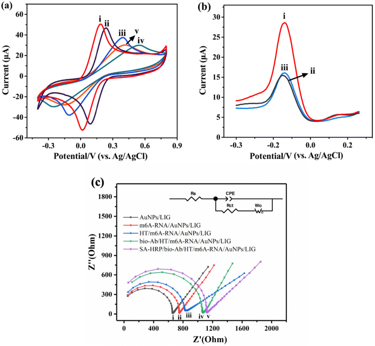 | ||
| Fig. 3 (a) CVs of SA-HRP/bio-Ab/HT/5mC-ssDNA/AuNPs/LIG at 0.01 μM 5mC-ssDNA in 0.1 M KCl containing 2.5 mM K3[Fe(CN)6] and 2.5 mM K4[Fe(CN)6]. (i–v): AuNPs/LIG, 5mC-ssDNA/AuNPs/LIG, HT/5mC-ssDNA/AuNPs/LIG, bio-Ab/HT/5mC-ssDNA/AuNPs/LIG, and SA-HRP/bio-Ab/HT/5mC-ssDNA/AuNPs/LIG, respectively. The start potential and switching potential were −0.4 V and 0.8 V, respectively. (b) Feasibility of the method at 0.01 μM m6A-RNA in 0.1 M PB containing 1 mM H2O2 and 1 mM HQ. (i–iii): m6A-RNA, unmethylated A-RNA (control), and m6A-RNA without SA-HRP, respectively. (c) Nyquist plots of SA-HRP/bio-Ab/HT/m6A-RNA/AuNPs/LIG. (i–v): AuNPs/LIG, m6A-RNA/AuNPs/LIG, HT/m6A-RNA/AuNPs/LIG, bio-Ab/HT/m6A-RNA/AuNPs/LIG, and SA-HRP/bio-Ab/HT/m6A-RNA/AuNPs/LIG, respectively. | ||
| Modification step | A (cm2) | Γ (mol cm−2) |
|---|---|---|
| LIG | 0.050 | 4.83 × 10⁻⁹ |
| AuNPs/LIG | 0.083 | 5.24 × 10⁻⁹ |
| 5mC-ssDNA/AuNPs/LIG | 0.080 | 4.88 × 10⁻⁹ |
| HT/5mC-ssDNA/AuNPs/LIG | 0.049 | 8.77 × 10⁻⁹ |
| bio-Ab/HT/5mC-ssDNA/AuNPs/LIG | 0.027 | 1.46 × 10⁻⁸ |
| SA-HRP/bio-Ab/HT/5mC-ssDNA/AuNPs/LIG | 0.020 | 1.86 × 10⁻⁸ |
Faraday's law (eqn (2)) was utilized to determine the amount of protein bound on the electrodes (Table 1). For HT/5mC-ssDNA/AuNPs/LIG, bio-Ab/HT/5mC-ssDNA/AuNPs/LIG and SA-HRP/bio-Ab/5mC-ssDNA/AuNPs/LIG, the values of Γ were 8.77 × 10⁻⁹, 1.46 × 10⁻⁸, and 1.86 × 10⁻⁸ mol cm−2, respectively. These results indicate that there were 5.83 × 10⁻⁹ mol cm−2 of bio-Ab and 4.00 × 10⁻⁹ mol cm−2 of SA-HRP bound to the electrode, in agreement with the CV findings mentioned earlier (Fig. 3a).
| Γ = Q/nFA | (2) |
493 C mol−1).
Fig. 3b shows the feasibility of our method. In comparison to m6A-RNA (curve (i)), the peak current observed for unmethylated A-RNA (curve (ii)) is weaker. This reduction in current is due to the inability of unmethylated A-RNA to bind to bio-Ab. Consequently, the introduction of SA-HRP is not possible, resulting in a diminished current response. Furthermore, SA-HRP contributes to the amplification of the current signal. Without SA-HRP, the electrode immobilized with m6A-RNA fails to yield a significant current (curve (iii)).
EIS measurements were also used to characterize the stepwise processes in a 0.1 M KCl solution containing 2.5 mM [Fe(CN)6]3−/[Fe(CN)6]4−, and the corresponding Nyquist plots are presented in Fig. 3c. The Nyquist diagrams are defined with the resistances (Rct and Rs), Warburg impedance (W) and capacitance (CPE). The EIS results are consistent with the CV characterization results shown in Fig. 3a. Compared with the deposition of AuNPs (curve (i)), in each subsequent modification step involving 5mC-ssDNA (curve (ii)), HT (curve (iii)), bio-Ab (curve (iv)), and SA-HRP (curve (v)), the impedance of the electrode increased gradually, evident by the enlargement of the semicircle domain. This increase in impedance indicates a slower stepwise electron transfer process.
Optimization of experimental conditions
The current signal for m6A-RNA and 5mC-ssDNA quantitative analysis was increased by the HRP-catalyzed H2O2–HQ redox reaction, where HRP was introduced to the electrode surface through the specific binding interaction of SA and biotin. Several factors that can influence this process were investigated, including the choice of blocking reagents, antibody concentration, antibody incubation time, SA-HRP concentration, and SA-HRP incubation time. To minimize detection errors caused by non-specific adsorption of antibodies and SA-HRP on the electrode, it is common to block the electrode with a suitable blocking reagent. MCH39 and BSA40 are commonly used electrode blocking reagents. Recently, HT or HDT has also been employed in some studies to improve the antifouling ability of electrodes.40,41 To investigate the effects of MCH, BSA, and HT, CV was employed. As shown in Fig. 4a, the HT-treated electrode shows a lower redox peak current (Ip) compared to MCH and BSA, which is due to the hydrophobic alkyl chains of HT forming a compact and protective layer on the electrode surface. This feature effectively shields the electrodes from interactions with hydrocarbons including H2O, thus improving the stability of the modified electrode.41 Meanwhile, we discussed the magnitude of current at different HT concentrations. After blocking electrodes with a higher concentration of HT, there was no significant increase in current (Fig. S2†). Therefore, a concentration of 1 mM HT was chosen as the blocking reagent following the modification of m6A-RNA or 5mC-ssDNA. | ||
| Fig. 4 Optimization of experimental conditions. (a) CVs of different blocking reagents at 0.01 μM 5mC-ssDNA: (i) 1% BSA, (ii) 1 mM MCH, and (iii) 1 mM HT. The start potential and switching potential were −0.4 V and 0.8 V, respectively. (b) Effect of anti-m6A-Ab concentration at 0.01 μM m6A-RNA. (c) Effect of anti-5mC-Ab concentration at 0.01 μM 5mC-ssDNA. (d) Effect of Ab incubation time at 0.01 μM 5mC-ssDNA. (e) Effect of SA-HRP concentration at 0.01 μM 5mC-ssDNA. (f) Effect of SA-HRP incubation time at 0.01 μM 5mC-ssDNA. Error bars represent standard deviations of three measurements. | ||
As shown in Fig. 4b–f, we explored the bio-Ab concentration and incubation time, as well as the SA-HRP concentration and incubation time using the DPV technique. The current response shows a gradual increase with an increase in the bio-Ab concentration and incubation time. Eventually, Ip reaches a stable state, indicating the saturation of antibody binding to 5mC-ssDNA or m6A-RNA, and the binding of SA to biotin on the antibody. Based on these results, we determined the optimal reaction conditions as follows: an anti-m6A-Ab concentration of 15 μg mL−1, an anti-5mC-Ab concentration of 20 μg mL−1, an antibody incubation time of 1 hour, a SA-HRP concentration of 0.5 U mL−1, and an SA-HRP incubation time of 30 minutes.
Electrochemical analysis
Under the optimum conditions, we evaluated the sensitivity of the biosensors for m6A-RNA and 5mC-ssDNA at different concentrations. The biosensor shows an increase in the peak current response of the H2O2–HQ redox reaction with the increasing concentration of m6A-RNA (Fig. 5a) and 5mC-ssDNA (Fig. 5c). Fig. 5b represents the calibration plot for various m6A-RNA concentrations ranging from 0.01 nM to 10 nM. (ΔI indicates the difference between the methylated strands and the unmethylated control strands.) The current response shows a good linear relationship with the logarithmic concentration of m6A-RNA. The regression equation was determined as ΔI = 4.83logc + 12.32 (R2 = 0.9980), with a limit of detection (LOD) calculated to be 2.81 pM. In the case of 5mC-ssDNA, Fig. 5c and d illustrate the DPV and calibration plot for the concentration range of 0.01–10 nM. The regression equation was ΔI = 9.82logc + 22.09 (R2 = 0.9903), and the LOD was calculated to be 9.53 pM. The LOD was determined using the regression equation by defining logc as the average ΔI of blank values plus three times the standard deviation (SD).
 | ||
| Fig. 5 (a and c) DPVs of the assembled sensors for the different concentration of m6A-RNA (a) and 5mC-ssDNA (c) in 0.01 M PB containing 1 mM H2O2–HQ. Curves (i–v) represent the concentration of 0.01, 0.1, 0.5, 1, and 10 nM. The regression calibration plots between ΔI and logarithmic concentration of m6A-RNA (b) and 5mC-ssDNA (d). Error bars represent standard deviations of three measurements. | ||
Comparing our proposed biosensor with previously reported strategies (Table S1†), our method demonstrated relatively desirable analytical performance.
Specificity, stability, repeatability
Assessing selectivity is critical to ensure the accurate detection of the target in real samples. Therefore, we explored the selectivity of anti-m6A-Ab (Fig. 6a) when using it for 0.01 μM m6A-RNA (curve (i)), unmethylated C-ssDNA (curve (ii)), 5mC-ssDNA (curve (iii)), and unmethylated A-RNA (curve (iv)), respectively. Under the same reaction conditions, only m6A-RNA exhibits a significantly higher Ip, indicating good selectivity and specific recognition between the antigen and antibody. To evaluate reproducibility, we performed experiments using five independently made electrodes and analyzed the relative standard deviation (RSD) of the peak current. Under the same experimental conditions and manipulation techniques, the five LIG electrodes exhibited slightly different currents. The results shown in Fig. 6b demonstrate an RSD of 6.85%, indicating the relatively good reproducibility of the method. Due to the inherent variability in the fabrication and measurement processes among the different LIG materials, the recorded currents also contain some variations, resulting in a RSD exceeding 5%. For the stability of the biosensors, we investigated both storage stability and consecutive scanning stability. Fig. 6c presents the results of the biosensors stored in a 4 °C refrigerator for different durations (0 day, 3 days, and 5 days). It is observed that Ip detected on day 5 exhibits a relative decrease compared to that on day 0, with an RSD of 9.42% for the 5-day detection. Regarding storage stability, we have considered that 5mC-ssDNA and m6A-RNA, both containing sulfhydryl groups, may impact the long-term stability of the fabricated sensors, potentially leading to an RSD greater than 5%. Consequently, we do not recommend prolonged storage of the prepared biosensors. Meanwhile, Fig. 6d shows Ip obtained from 10 consecutive scans of a single biosensor with an RSD of 2.08%, indicating that the developed method possesses excellent scanning stability. | ||
| Fig. 6 Specificity, reproducibility and stability measurement of 0.01 μM m6A-RNA. (a) Specificity measurement, (i), unmethylated C-ssDNA (ii), 5mC-ssDNA (iii), and unmethylated A-RNA (iv). (b) Reproducibility of five independent biosensors. (c) Stability test for five days. (d) Stability test of consecutive scanning. Error bars represent standard deviations of three measurements. | ||
| Added (ng μL−1) | m6A-RNA | 5mC-ssDNA | ||
|---|---|---|---|---|
| Recovery (%) | RSD (%, n = 3) | Recovery (%) | RSD (%, n = 3) | |
| 0.01 | 106.5 | 1.2 | 98.8 | 0.7 |
| 0.05 | 111.0 | 0.8 | 97.4 | 1.3 |
| 0.1 | 105.4 | 1.3 | 95.3 | 0.7 |
Conclusions
In conclusion, we have developed an electrochemical biosensor based on the promising LIG electrodes for the detection of m6A-RNA and 5mC-ssDNA utilizing the peculiar recognition of the antibody and antigen. The catalysis of HRP for the H2O2–HQ redox reaction provided the electrochemical current signal and the incorporation of AuNPs enhanced the conductivity and sensitivity of the LIG electrodes. Remarkably, the LODs for m6A-RNA and 5mC-ssDNA were achieved at 2.81 pM and 9.53 pM, respectively. Compared to other strategies, this method offers simplicity and avoids complex operational steps. Furthermore, our method holds potential for the development of POCT techniques for nucleic acid methylation detection in clinical applications, thus providing novel insights for future advancements.Author contributions
Jingyi Guo: investigation, methodology, formal analysis, writing – original draft, visualization, software, and data curation. Mei Zhao and Chen Chen: investigation, methodology, formal analysis, visualization, software, and data curation. Fang Wang: supervision, funding acquisition, project administration, conceptualization, and writing – review & editing. Zilin Chen: supervision and writing – review & editing.Conflicts of interest
There are no conflicts to declare.Acknowledgements
This work was supported by the National Natural Science Foundation of China (Grant No. 22277094 and 21778041).References
- N. Jonkhout, J. Tran, M. A. Smith, N. Schonrock, J. S. Mattick and E. M. Novoa, RNA, 2017, 23, 1754–1769 CrossRef CAS PubMed.
- T. Y. Wang, S. Kong, M. Tao and S. Q. Ju, Mol. Cancer, 2020, 19, 88 CrossRef CAS.
- Y. Yang, P. J. Hsu, Y. S. Chen and Y. G. Yang, Cell Res., 2018, 28, 616–624 CrossRef CAS.
- B. C. Yang, J. Q. Wang, Y. Tan, R. Z. Yuan, Z. S. Chen and C. Zou, Pharmacol. Res., 2021, 174, 105937 CrossRef CAS PubMed.
- H. Z. Zhuang, B. Yu, D. Tao, X. Y. Xu, Y. J. Xu, J. Wang, Y. Jiao and L. L. Wang, Mol. Cancer, 2023, 22, 91 CrossRef CAS.
- D. Schubeler, Nature, 2015, 517, 321–326 CrossRef CAS PubMed.
- R. H. Xu, W. Wei, M. Krawczyk, W. Q. Wang, H. Y. Luo, K. Flagg, S. H. Yi, W. Shi, Q. L. Quan, K. Li, L. H. Zheng, H. Zhang, B. A. Caughey, Q. Zhao, J. Y. Hou, R. Z. Zhang, Y. X. Xu, H. M. Cai, G. Li, R. Hou, Z. Zhong, D. N. Lin, X. Fu, J. Zhu, Y. O. Duan, M. X. Yu, B. W. Ying, W. G. Zhang, J. Wang, E. Zhang, C. Zhang, O. L. Li, R. P. Guo, H. Carter, J. K. Zhu, X. K. Hao and K. Zhang, Nat. Mater., 2017, 16, 1155–1161 CrossRef CAS.
- J. Liu, B. T. Harada and C. He, Trends Cell Biol., 2019, 29, 487–499 CrossRef CAS PubMed.
- C. L. Xiao, S. Zhu, M. H. He, D. Chen, Q. Zhang, Y. Chen, G. L. Yu, J. B. Liu, S. Q. Xie, F. Luo, Z. Liang, D. P. Wang, X. C. Bo, X. F. Gu, K. Wang and G. R. Yan, Mol. Cell, 2018, 71, 306–318 CrossRef CAS PubMed.
- M. Weber, J. J. Davies, D. Wittig, E. J. Oakeley, M. Haase, W. L. Lam and D. Schubeler, Nat. Genet., 2005, 37, 853–862 CrossRef CAS.
- Z. D. Zhong, Y. Y. Xie, H. X. Chen, Y. L. Lan, X. H. Liu, J. Y. Ji, F. Wu, L. M. Jin, J. K. Chen, D. W. Mak, Z. Zhang and G. Z. Luo, Nat. Commun., 2023, 14, 1906 CrossRef CAS.
- W. Huang, C. B. Qi, S. W. Lv, M. Xie, Y. Q. Feng, W. H. Huang and B. F. Yuan, Anal. Chem., 2016, 88, 1378–1384 CrossRef CAS.
- F. Lyko, B. H. Ramsahoye and R. Jaenisch, Nature, 2000, 408, 538–540 CrossRef CAS PubMed.
- T. Dai, Q. L. Pu, Y. C. Guo, C. Zuo, S. L. Bai, Y. J. Yang, D. Yin, Y. Li, S. C. Sheng, Y. Y. Tao, J. Fang, W. Yu and G. M. Xie, Biosens. Bioelectron., 2018, 114, 72–77 CrossRef CAS.
- H. S. Yin, Y. L. Zhou, Z. Q. Yang, Y. L. Guo, X. X. Wang, S. Y. Ai and X. S. Zhang, Sens. Actuators, B, 2015, 221, 1–6 CrossRef CAS.
- J. Huang, S. Zhang, F. Mo, S. S. Su, X. Chen, Y. Li, L. C. Fang, H. Huang, J. Deng, H. M. Liu, X. L. Yang and J. S. Zheng, Biosens. Bioelectron., 2019, 127, 155–160 CrossRef CAS.
- E. Povedano, A. Valverde, V. R. Montiel, M. Pedrero, P. Yanez-Sedeno, R. Barderas, P. San Segundo-Acosta, A. Pelaez-Garcia, M. Mendiola, D. Hardisson, S. Campuzano and J. M. Pingarron, Angew. Chem., Int. Ed., 2018, 57, 8194–8198 CrossRef CAS PubMed.
- S. A. Hong, Y. J. Kim, S. J. Kim and S. Yang, Biosens. Bioelectron., 2018, 107, 103–110 CrossRef CAS PubMed.
- A. Y. El-Moghazy, J. Q. Huo, N. Amaly, N. Vasylieva, B. D. Hammock and G. Sun, ACS Appl. Mater. Interfaces, 2020, 12, 6159–6168 CrossRef CAS.
- K. D. Hansen, W. Timp, H. C. Bravo, S. Sabunciyan, B. Langmead, O. G. McDonald, B. Wen, H. Wu, Y. Liu, D. Diep, E. Briem, K. Zhang, R. A. Irizarry and A. P. Feinberg, Nat. Genet., 2011, 43, 768–775 CrossRef CAS.
- M. Labib, E. H. Sargent and S. O. Kelley, Chem. Rev., 2016, 116, 9001–9090 CrossRef CAS PubMed.
- J. Lin, Z. W. Peng, Y. Y. Liu, F. Ruiz-Zepeda, R. Q. Ye, E. L. Samuel, M. J. Yacaman, B. I. Yakobson and J. M. Tour, Nat. Commun., 2014, 5, 5714 CrossRef CAS PubMed.
- A. Ghanam, A. A. Lahcen, T. Beduk, H. N. Alshareef, A. Amine and K. N. Salama, Biosens. Bioelectron., 2020, 168, 112509 CrossRef CAS.
- X. Y. Zhu, L. Lin, R. M. Wu, Y. F. Zhu, Y. Y. Sheng, P. C. Nie, P. Liu, L. L. Xu and Y. P. Wen, Biosens. Bioelectron., 2021, 179, 113062 CrossRef CAS.
- X. Han, R. Q. Ye, Y. Chyan, T. Wang, C. H. Zhang, L. L. Shi, T. Zhang, Y. Zhao and J. M. Tour, ACS Appl. Nano Mater., 2018, 1, 5053–5061 CrossRef CAS.
- Y. L. Li, D. X. Luong, J. B. Zhang, Y. R. Tarkunde, C. Kittrell, F. Sargunaraj, Y. S. Ji, C. J. Arnusch and J. M. Tour, Adv. Mater., 2017, 29, 1700496 CrossRef.
- F. M. Vivaldi, A. Dallinger, A. Bonini, N. Poma, L. Sembranti, D. Biagini, P. Salvo, F. Greco and F. Di Francesco, ACS Appl. Mater. Interfaces, 2021, 13, 30245–30260 CrossRef CAS PubMed.
- X. Y. Ou, Q. L. Pu, S. C. Sheng, T. Dai, D. Gou, W. Yu, T. Y. Yang, L. Dai, Y. J. Yang and G. M. Xie, Microchim. Acta, 2020, 187, 31 CrossRef CAS.
- N. Zhang, J. Yang and C. G. Hu, Sens. Actuators, B, 2022, 357, 131394 CrossRef CAS.
- A. Prabhakaran and P. Nayak, ACS Appl. Nano Mater., 2020, 3, 391–398 CrossRef CAS.
- Y. Zhang, N. Li, Y. J. Xiang, D. B. Wang, P. Zhang, Y. Y. Wang, S. Lu, R. Q. Xu and J. Zhao, Carbon, 2020, 156, 506–513 CrossRef CAS.
- Z. F. Wan, M. Umer, M. Lobino, D. Thiel, N. T. Nguyen, A. Trinchi, M. J. A. Shiddiky, Y. S. Gao and Q. Li, Carbon, 2020, 163, 385–394 CrossRef CAS.
- S. Rauf, A. A. Lahcen, A. Aljedaibi, T. Beduk, J. Ilton de Oliveira Filho and K. N. Salama, Biosens. Bioelectron., 2021, 180, 113116 CrossRef CAS.
- H. M. Yang, Y. F. Wang, J. Tang, F. Wang and Z. L. Chen, Microchim. Acta, 2021, 188, 250 CrossRef CAS PubMed.
- A. K. Yagati, A. Behrent, S. Beck, S. Rink, A. M. Goepferich, J. H. Min, M. H. Lee and A. J. Baeumner, Biosens. Bioelectron., 2020, 164, 112272 CrossRef CAS PubMed.
- F. C. Wang, K. D. Wang, X. Dong, X. S. Mei, Z. Y. Zhai, B. X. Zheng, J. Lv, W. Q. Duan and W. J. Wang, Appl. Surf. Sci., 2017, 419, 893–900 CrossRef CAS.
- G. Y. Wang, J. Y. Chen, H. Lu, Y. T. Chen and Y. X. Li, Analyst, 2021, 146, 6631–6642 RSC.
- G. Castillo, I. Lamberti, L. Mosiello and T. Hianik, Electroanalysis, 2012, 24, 512–520 CrossRef CAS.
- L. Bábelová, M. E. Sohová, A. Poturnayová, M. Buríková, J. Bizík and T. Hianik, Electroanalysis, 2018, 30, 1487–1495 CrossRef.
- D. C. Ferreira, M. R. Batistuti, B. B. Junior and M. Mulato, Bioelectrochemistry, 2021, 137, 107586 CrossRef CAS.
- T. Kondo, K. Tamura, S. Takakusagi, K. Kitamura, M. Takahasi, J. Mizuki and K. Uosaki, J. Solid State Electrochem., 2009, 13, 1141–1145 CrossRef CAS.
Footnote |
| † Electronic supplementary information (ESI) available. See DOI: https://doi.org/10.1039/d3an01628e |
| This journal is © The Royal Society of Chemistry 2024 |