Spent shell as a calcium source for constructing calcium vanadate for high-performance Zn-ion batteries†
Ningze
Gao
,
Feng
Li
,
Zhiyuan
Wang
,
Xianghua
Kong
,
Lei
Wang
 ,
Yuanxiang
Gu
 * and
Maojuan
Bai
*
College of Environment and Safety Engineering, Qingdao University of Science and Technology, Qingdao 266042, China. E-mail: gyx0524@126.com; baimaojuan@qust.edu.cn
First published on 30th November 2023
Abstract
In this article, waste shell is directly used as a raw material to synthesize CaV3O7 as a cathode for aqueous zinc ion batteries. The obtained cathode material exhibits better performance than that of CaV3O7 prepared from pure calcium carbonate as a raw material. At 0.1 A g−1, the CaV3O7 prepared by spent shell as a calcium source displays a highly reversible discharge capacity of 373 mA h g−1. A high initial discharge capacity of 177.7 mA h g−1 can be gained at 5.0 A g−1, and the specific capacity remains at 133.3 mA h g−1 with a capacity retention of 75% after 3000 cycles. This work may spark inspiration for energy storage and generate more effective routes for recycling solid waste.
At present, resource recycling measures are limited in scale and have low output utilization; high value utilization of solid waste is urgently needed.1 Some attempts have been made to explore resourceful solid waste utilization in the energy field.2,3 Shellfish products are consumed very widely around the world,4,5 and consist of 95% calcium carbonate along with a small amount of organic and inorganic matter.6,7 Apparently, shells are ideal and natural biomass calcium due to their reproducibility and relatively low price, and could be a great substitute for industrial calcium carbonate in some areas. There have been some attempts to develop the reuse of shells in some fields, including heavy metal adsorption,8,9 agriculture,10 and substitutes for padding.11,12 However, the reuse of shells is still unsatisfactory and most waste shells are only disposed of in landfills.13 To our best knowledge, there has been no attempt to explore the reuse of shells in the energy field.
Aqueous zinc ion batteries (AZIBs) have recently set off overwhelming research surges because of safety performance, environmental friendliness and comparatively low cost.14,15 In particular, vanadium-based materials are one of the promising cathode materials because of the multiple valence states of V and variable crystal structure.16,17 However, the unstable layered structure, narrow interlayer spacing, and strong electrostatic interaction between Zn2+ and the host materials result in poor electrochemical performance of vanadium-based materials.18,19 Recently, it has been shown that chemically inserted metal ions can expand the lattice spacing, and facilitate fast ion diffusion to improve electrochemical performance by the pillar effect.20–22 Ca2+ as a bivalent ion can provide a large interlayer spacing, and result in a strong “pillar effect” in the layered structure due to strong electrostatic interaction with oxygen atoms on the surface of the V–O layer.23,24 In addition, Ca2+ has better diffusion kinetics during the cycling process because Ca2+ has a larger radius and smaller surface charge density than Zn2+.25,26
In this report, waste shell powder as a raw material is directly used to synthesize calcium vanadate nanomaterials (denoted as CVO-s) for AZIBs. As a comparison, calcium vanadate is prepared by the same process as that of CVO-s using pure calcium carbonate as a calcium source (denoted as CVO). The CVO-s exhibits higher reversible capacity and better cycling stability compared to those of CVO. This work provides a new pathway for the reutilization of solid waste in the energy field, and it is of great importance in terms of resource recycling, ecological benefits, and even energy evolution.
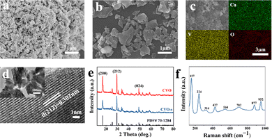
The SEM image of the as-prepared CVO-s is shown in Fig. 1, which displays that the CVO-s is a uniform nanoparticle with a size of 200–300 nm. The SEM elemental mapping verifies the even distribution of Ca, V, and O elements (Fig. 1c). The HRTEM image presented in Fig. 1d demonstrates that the lattice distance of 0.302 nm corresponds to the (212) plane of CaV3O7 with excellent crystallinity. The SEM image of CVO in Fig. 1b demonstrates that CVO is irregular particles with a larger particle size. The difference in morphology should be due to co-doped elements in the CVO-s coming from the shell powder. Therefore, the contents of doped metallic elements in the shell powder and CVO-s material are investigated by ICP tests and the corresponding results are illustrated in Table S1 (ESI†). It can be seen that Na, Mg, Al, and Fe as the main elements in the shell powder are effectively doped into the CVO-s material. Therefore, the Na, Mg, Al and Fe elements are added into the CVO according to their corresponding amounts in CVO-s to obtain a doped calcium vanadate sample (denoted as CVO-d). Fig. S1 (ESI†) gives the SEM and elemental mapping images of CVO-d. The doped elements are uniformly distributed in CVO-d, indicating the homogenous incorporation of the metal ions. The CVO-d sample is homogeneous particles with a smaller size than CVO, which indicates that metal doping is helpful to prepare even nanoparticles with smaller sizes. Ali et al. reported co-doped ZnO and found an inverse relationship between dopant concentration and grain size.27 The decrease of particle size results from the influence of doping elements on the crystallization and nucleation rate of the material, which hinders the crystallite growth of particles.27,28
 | ||
| Fig. 1 SEM images of CVO-s (a) and CVO (b). SEM elemental mapping images of CVO-s (c). TEM and HRTEM images (d) of CVO-s. XRD patterns (e) of CVO-s and CVO. Raman spectrum (f) of CVO-s. | ||
The XRD patterns of the CVO and CVO-s samples are shown in Fig. 1e. Their XRD peaks are very similar, and all diffraction peaks can be indexed to the CaV3O7 crystal structure (PDF# 70-1284), which indicates that the presence of impurities in the shell powder cannot affect the crystal structure of CaV3O7. The Raman spectrum in Fig. 1f is used to investigate the structure of the CVO-s. Several main peaks are located at 157, 224, 314, 427, 544, 702, 877, and 952 cm−1. The bending vibrations of O–V–O and V–O–V bonds can be found at 157 cm−1, 224 cm−1, and 427 cm−1, while the peaks at 314, 544, 702, 877 and 952 cm−1 can be ascribed to V–O.29 The vibrational motion of lattice water is at 314 cm−1, indicating the existence of water in CVO-s. The Raman spectrum of the CVO sample is also displayed in Fig. S2 (ESI†), which shows no difference from that of CVO-s.
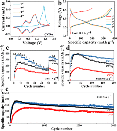
The first four CV curves of CVO-s are displayed in Fig. 2a. An irreversible electrochemical reaction can be confirmed from an obvious difference in the CV curves between the first cycle and subsequent cycles. From the second cycle, two pairs of redox peaks at 0.89/0.524 V and 0.7/1.11 V result from the continuous redox couples V5+/V4+ and V4+/V3+, proving multistep intercalation/extraction processes of Zn2+ in the CVO-s cathode. In subsequent cycling, there is no obvious change in the CV curves, which states high structural stability and superior electrochemical reversibility of the cathode material. Fig. 2b displays the charge–discharge curves of the CVO-s electrode at 0.1 A g−1, and the charge–discharge curve of the first cycle is different from those of the subsequent cycles, which matches the CV results. After the first cycle, the charge–discharge curves gradually become stable, and a high specific capacity of 373 mA h g−1 can be gained in the fifth cycle. Fig. 2c compares the rate capability of the CVO-s and CVO electrodes at different current densities. The CVO-s electrode exhibits remarkable specific capacities of 378, 366, 341, 308, 273, 247, 199, 182, 150, and 129 mA h g−1 at 0.1, 0.3, 0.5, 1.0, 2.0, 3.0, 5.0, 6.0, 8.0 and 10.0 A g−1, respectively. When the current density reverts to 0.1 A g−1, a specific capacity of 92.6% of the initial capacity can be kept, demonstrating its outstanding electrochemical stability. In contrast, the CVO shows low specific capacities of 153, 160, 147, 126, 108, 98, 87, 83, 77 and 72 mA h g−1 at the corresponding current densities. To further confirm the superior electrochemical performance of the CVO-s material, the prolonged cycling performance of the CVO-s and CVO electrodes is demonstrated in Fig. 2d and e. At 0.5 A g−1, CVO-s possesses a maximum specific capacity of 308.8 mA h g−1, while that of CVO is only 150 mA h g−1, less than half of the maximum specific capacity of the CVO-s electrode. After 200 cycles, the discharge capacity of CVO-s is still 256 mA h g−1 with a maximum capacity retention rate of 83%. Even at 5 A g−1, the CVO-s electrode still owns a high maximum specific capacity of 177.7 mA h g−1, which is higher than that of CVO. After 3000 cycles, the specific capacity of CVO-s still keeps at 105.5 mA h g−1 with a maximum capacity retention rate of 75%. The CVO material exhibits a maximum specific capacity of 134.7 mA h g−1 and there is a low-capacity retention rate of 20.4% after 3000 cycles. It is obvious that the CVO-s possess higher specific capacity and superior cycling stability. When Na, Mg, Al and Fe elements were added into CVO, the rate performance of the obtained CVO-d is demonstrated in Fig. 2c. The CVO-d material exhibits obviously better rate performance than CVO at each current density although the rate performance of the CVO-d is not as good as that of CVO-s. The cycling performance of the CVO-d is given in Fig. 2d and e at 0.5 and 5.0 A g−1. The specific capacities and cycling stability of CVO-d are obviously higher than those of CVO. When the Na, Mg, Al or Fe elements are doped into the CVO material alone, the cycling performances of the obtained materials are shown in Fig. S3 (ESI†). It is obvious that all single doped cathode materials display worse electrochemical performance than CVO-d, which further confirms that doping, especially co-doping, can effectively improve the electrochemical properties. The CVO-s material in our report could be a promising cathode for AZIBs, displaying a more superior electrochemical performance than those of previously reported V-based cathodes; a comparison of their electrochemical performance is depicted in Fig. S4 (ESI†). The superior electrochemical performance of CVO-s should be attributed to the synergistic effect of co-doping. The doped metal ions can interact with the oxygen anions between the layers, which leads to the formation of M–O (M = Fe, Al, Na, and Mg) bonds. The M–O bond can affect the interlayer spacing and van der Waals forces between the layers by controlling the thermodynamic and kinetic properties of the intercalation ions, which leads to more effective Zn2+ intercalation kinetics and improved structure stability.30,31 In addition, the doping of multiple elements leads to a smaller size of the cathode material, which can increase the contact area of the CVO-s with the electrolyte and improve the electrochemical utilization of the active material. In addition, the smaller size is conductive to accelerating the electrochemical reaction kinetics and shortening the diffusion distance of charge/ion transport, thus enhancing the electrochemical performance.32,33
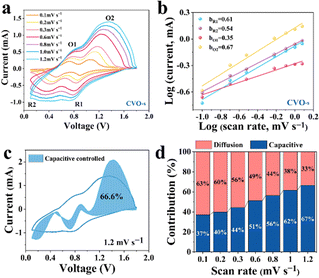
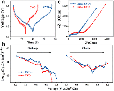
To estimate the electrochemical kinetics of the materials, CV curves at different scan rates are shown in Fig. 3a. The relationship of peak current (i) and scan rate (v) can be described as i = avb, where i stands for the current, and v is the scan rate, while a and b represent adjustable parameters. A value of b approaching 1 acts for a surface capacitive behaviour, while the a value of 0.5 indicates a main diffusion process.34 As illustrated in Fig. 3b, the b values of the four peaks are 0.61, 0.54, 0.35, and 0.67, respectively, demonstrating that the Zn ion storage is mainly controlled by the diffusion process.35 Moreover, the capacity can be separated into capacitive (k1v) and diffusion control (k2v1/2) contributions, which can be expressed as: i = k1v + k2v1/2. In the equation, k1 and k2 represent the capacitance and diffusion control process coefficients, respectively.36 In Fig. 3c, the proportion of surface contribution is 66.6%. In addition, as can be seen from the histogram in Fig. 3d, the capacitance contributions of the CVO-s electrodes are 37, 40, 44, 51, 56, 62 and 67% at the scan rates of 0.1, 0.2, 0.3, 0.6, 0.8, 1.0 and 1.2 mV s−1, respectively. Therefore, the high storage capacity of the CVO-s electrode should be attributed to the fast Zn2+ ion diffusion rate. The reaction kinetics on the CVO-s and CVO electrodes are investigated by GITT measurements and the results are displayed in Fig. 4a. The DZn2+ value (Fig. 4b) of the CVO-s electrode is higher than those of the CVO and reported zinc ion batteries with CuO (10−12–10−16),37 MnO2 (10−12–10−6),38 and ZnxMnO2 cathodes (10−12–10−15).39 A faster Zn2+ migration provided by the CVO-s electrode is beneficial for insertion or removal of zinc ions.40 It is notable that the charge transfer resistance of the CVO-s electrode is lower than that of the CVO electrode, indicating the faster reaction kinetics of CVO-s. In addition, as shown in Fig. S5 (ESI†), the diameter of the semicircle of the CVO-s electrode decreases as the cycle number increases. After electrochemical activation, the CVO-s electrode exhibits a smaller semicircle at high frequency, showing that the activated CVO-s electrode endows superior ion diffusion and electron transport characteristics.41,42
In summary, a novel strategy was used to build a bridge between energy conversion and solid waste recycling by applying shell powder as a raw material to synthesize calcium vanadate nanomaterials as cathodes for constructing high-performance AZIBs. The impurity elements in the shell powder not only do not damage the electrochemical properties of the prepared electrode materials, but also help in improving the electrochemical properties. The CVO-s cathode material has more superior electrochemical performance compared with CVO material prepared by using chemical calcium carbonate due to the doped metallic elements coming from the shell powder. This study provides a strategy to build vanadium-based materials for high-performance AZIBs and provides a new route for the recycling of solid wastes.
Conflicts of interest
There are no conflicts to declare.Notes and references
- L. Zhu, D. Zhu, G. He, H. Wang, X. Zhang, J. Lin, Y. Qi and X. Liang, Nat. Rev. Earth Environ., 2022, 3, 141–155 Search PubMed.
- Z. Xu, N. Zhang and X. Wang, Nano Energy, 2022, 102, 107724 CrossRef CAS.
- M. Xie, X. Zhu, D. Li, Z. Xu, Y. Huang, H. Zha and C. Jia, J. Power Sources, 2021, 514, 230593 CrossRef CAS.
- L. Cao, R. Naylor, P. Henriksson, D. Leadbitter, M. Metian, M. Troell and W. B. Zhang, Science, 2015, 347, 133–135 CrossRef CAS.
- J. Zhang, H. Chen, T. Mu and Y. Pan, IOP Conf. Ser. Earth Environ. Sci., 2018, 170, 032031 CrossRef.
- G. O. Bamigboye, A. T. Nworgu, A. O. Odetoyan, M. Kareem, D. O. Enabulele and D. E. Bassey, J. Build. Eng., 2021, 34, 101864 CrossRef.
- B. A. Tayeh, M. W. Hasaniyah, A. M. Zeyad and M. O. Yusuf, J. Cleaner Prod., 2019, 237, 117723 CrossRef CAS.
- H. Huang, H. Liu, R. Zhang, Y. Chen, L. Lei, C. Qiu and H. Xu, J. Environ. Manage., 2022, 319, 115683 CrossRef CAS PubMed.
- A. Larraguibel, A. Navarrete-Calvo, S. García, V. F. Armijos and M. A. Caraballo, J. Cleaner Prod., 2020, 274, 123450 CrossRef CAS.
- J. P. Morris, T. Backeljau and G. Chapelle, Rev. Aquac., 2019, 11, 42–57 CrossRef.
- A. Edalat-Behbahani, F. Soltanzadeh, M. Emam-Jomeh and Z. Soltan-Zadeh, Eur. J. Environ. Civ. Eng., 2019, 25, 1874–1893 CrossRef.
- H. Lin, Q. Hou, Y. Luo, G. Hu, J. Yu and R. Yu, J. Environ. Manage., 2022, 315, 115142 CrossRef CAS.
- J. Lu, X. Cong, Y. Li, Y. Hao and C. Wang, J. Cleaner Prod., 2018, 172, 1978–1985 CrossRef CAS.
- T. Zhou, L. Xie, Q. Han, X. Yang, L. Zhu and X. Cao, Chem. Eng. J., 2022, 445, 136789 CrossRef CAS.
- X. Wang, Z. Zhang, M. Huang, J. Feng, S. Xiong and B. Xi, Nano Lett., 2022, 22, 119–127 CrossRef CAS PubMed.
- Q. Zong, Q. Wang, C. Liu, D. Tao, J. Wang, J. Zhang, H. Du, J. Chen, Q. Zhang and G. Cao, ACS Nano, 2022, 16, 4588–4598 CrossRef CAS PubMed.
- Z. Pang, B. Ding, J. Wang, Y. Wang, L. Xu, L. Zhou, X. Jiang, X. Yan, J. P. Hill, L. Yu and Y. Yamauchi, Chem. Eng. J., 2022, 446, 136861 CrossRef.
- T. Lv, Y. Peng, G. Zhang, S. Jiang, Z. Yang, S. Yang and H. Pang, Adv. Sci., 2023, e2206907 CrossRef.
- D. Zhao, X. Wang, W. Zhang, Y. Zhang, Y. Lei, X. Huang, Q. Zhu and J. Liu, Adv. Funct. Mater., 2023, 10, 2206907 Search PubMed.
- Z. Feng, Y. Zhang, Y. Zhao, J. Sun, Y. Liu, H. Jiang, M. Cui, T. Hu and C. Meng, Nanoscale, 2022, 14, 8776–8788 RSC.
- W. He, C. Meng, Z. Ai, D. Xu, S. Liu, Y. Shao and Y. Wu, Chem. Eng. J., 2023, 454, 140260 CrossRef CAS.
- T. Lv, G. Zhu, S. Dong, Q. Kong, Y. Peng, S. Jiang, G. Zhang, Z. Yang, S. Yang, X. Dong, H. Pang and Y. Zhang, Angew. Chem., Int. Ed., 2022, e202216089 Search PubMed.
- X. Liang, J. Hao, B. Tan, X. Lu and W. Li, J. Power Sources, 2020, 472, 228507 CrossRef CAS.
- Y. Du, X. Wang, Y. Zhang, H. Zhang, J. Man, K. Liu and J. Sun, Chem. Eng. J., 2020, 434, 134642 CrossRef.
- W. Zhou, M. Chen, A. Wang, A. Huang, J. Chen, X. Xu and C.-P. Wong, J. Energy Chem., 2021, 52, 377–384 CrossRef CAS.
- C. Xia, J. Guo, P. Li, X. Zhang and H. N. Alshareef, Angew. Chem., Int. Ed., 2018, 57, 3943–3948 CrossRef CAS.
- A. M. Ali, A. Maphudz, A. Basahel, U. Saeed, A. A. Taimoor, A. U. Rather and H. Zhang, Asia-Pac. J. Chem. Eng., 2018, 13(2), e2183 CrossRef.
- D. Singhwal, A. Khatri and P. S. Rana, Optik, 2023, 274, 170562 CrossRef CAS.
- H. Yang, P. Ning, Z. Zhu, L. Yuan, W. Jia, J. Wen, G. Xu, Y. Li and H. Cao, Chem. Eng. J., 2022, 438, 135495 CrossRef CAS.
- J. Carrasco, J. Phys. Chem. C, 2014, 118, 19599–19607 CrossRef CAS.
- A. Parija, D. Prendergast and S. Banerjee, ACS Appl. Mater. Interfaces, 2017, 9, 23756–23765 CrossRef CAS.
- H. Wang, Q. He, F. Zhan and L. Chen, J. Colloid Interface Sci., 2023, 630, 286–296 CrossRef CAS.
- F. Li, H. Sheng, H. Ma, Y. Qi, M. Shao and J. Yuan, ACS Appl. Energy Mater., 2023, 6, 6201–6213 CrossRef CAS.
- H. Tang, W. Chen, N. Li, Z. Hu, L. Xiao, Y. Xie, L. Xi, L. Ni and Y. Zhu, Energy Storage Mater., 2022, 48, 335–343 CrossRef.
- R. Wei, X. Wang, B. Xi, Z. Feng, H. Li, W. Chen, Y. Jia, J. Feng and S. Xiong, ACS Appl. Energy Mater., 2020, 3, 5343–5352 CrossRef CAS.
- J. Zheng, C. Liu, M. Tian, X. Jia, E. P. Jahrman, G. T. Seidler, S. Zhang, Y. Liu, Y. Zhang, C. Meng and G. Cao, Nano Energy, 2020, 70, 104519 CrossRef CAS.
- J. Meng, Z. Yang, L. Chen, H. Qin, F. Cui, Y. Jiang and X. Zeng, Mater. Today Energy, 2020, 15, 100370 CrossRef.
- S. Bi, Y. Wu, A. Cao, J. Tian and S. Zhang, Mater. Today Energy, 2020, 18, 100548 CrossRef CAS.
- J. Wang, J. Wang, H. Liu, C. Wei and F. Kang, J. Mater. Chem. A, 2019, 7, 13727 RSC.
- X. Wang, A. Naveed, T. Zeng, T. Wan, H. Zhang and Y. Zhou, Chem. Eng. J., 2022, 446, 137090 CrossRef CAS.
- W. Deng, Y. Xu, X. Zhang, C. Li, Y. Liu, K. Xiang and H. Chen, J. Alloys Compd., 2022, 903, 163824 CrossRef CAS.
- H. Wang, M. Liang, J. Gao, C. Ma, Y. Zhao and Z. Miao, Colloids Surf., A, 2022, 643, 128804 CrossRef CAS.
Footnote |
| † Electronic supplementary information (ESI) available. See DOI: https://doi.org/10.1039/d3cc04440h |
| This journal is © The Royal Society of Chemistry 2024 |


