 Open Access Article
Development of a double-side ordered membrane electrode assembly based on titanium nitride nanoarrays
Lingfeng
Xuan
a,
Deqing
Mei
a,
Caiying
Zhou
b,
Wenze
Mao
b and
Yancheng
Wang
 *a
*a
aState Key Lab of Fluid Power and Mechatronic Systems, School of Mechanical Engineering, Zhejiang University, Hangzhou 310027, China. E-mail: yanchwang@zju.edu.cn
bZhejiang Province Key Laboratory of Advanced Manufacturing Technology, School of Mechanical Engineering, Zhejiang University, Hangzhou 310027, China
First published on 21st March 2024
Abstract
The membrane electrode assembly (MEA) plays a crucial role in the functionality of proton exchange membrane fuel cells (PEMFCs). The channels present within the catalyst layer of MEAs exhibit a disordered configuration, which consequently give rise to low efficiency in mass transportation. In order to enhance the mass transfer performance and the corrosion resistance of the catalyst layer, this paper developed a double-side ordered MEA based on TiN nanorod arrays. We synthesized TiN nanorod arrays on the ITO surface by a seed-assisted hydrothermal reaction and nitriding treatment, and coated the catalyst uniformly on the TiN support by ultrasonic spraying. Then the double-side ordered MEA was fabricated by transfer printing, and achieved a peak power of 678.30 mW cm−2 with a cathode platinum loading of 0.2 mg cm−2 at 80 °C and anode saturated humidity. After 200 hours of accelerated stress test (AST) at 90 °C and 30/30% relative humidity, the peak performance only dropped by 4.8%. These results provide substantial evidence for the effectiveness of our developed double-side ordered MEA which can mitigate catalyst polarization corrosion. Thus, this study reveals the immense potential of the TiN nanorod array-based double-side ordered MEA in advancing the development of efficient and stable MEAs.
Keywords: PEMFC; Preparation of MEA; Ordered MEA; TiN nanorod array; Catalyst carrier.
1 Introduction
Proton exchange membrane fuel cells (PEMFCs) can be regarded as a clean and highly efficient energy conversion technology that employs renewable hydrogen as a fuel source, and solely generates water as a by-product.1,2 Fuel cells have been widely used in the spheres of renewable energy, including transportation, power generation, and portable devices.3,4 Nonetheless, the crucial challenges of hydrogen–oxygen fuel cells for large-scale commercial application are the high platinum load and insufficient durability of the MEA.5 The MEA comprises a proton exchange membrane (PEM) sandwiched between two catalyst layers (CLs) and two gas diffusion layers (GDLs).6 The conventional configuration of the MEA exhibits several limitations, such as hindered mass transportation, catalyst aggregation, and membrane degradation.7–9 Consequently, it is essential to investigate novel MEA structures that can enhance the performance and surmount the catalyst polarization corrosion problem. The ordered structure of the MEA facilitates the regular arrangement of catalyst supports on the PEM surface, thereby providing well-defined channels for reactant gas diffusion and effective water management.10–12The preparation of corrosion-resistant nanomaterials is important to promote the advancement of ordered catalyst layers. Diverse materials, such as organic compounds,13–16 carbon nanotubes,17,18 and metal compounds,19,20 have been extensively utilized. The nanostructured thin film electrode (NSTF) developed by 3M® is one of the most typical ordered nanostructured MEAs and has been commercialized.21,22 Yang et al.23 proposed a new catalyst/electrode structure, named the coaxial nanowire electrode (CANE), which consists of vertically aligned nanowires, each of which has an ion-conducting core wrapped in a nanoscale Pt film. Through accelerated stress tests, it was found that the CANE only had 2% and 5% performance losses in the catalyst support and catalyst tests, respectively. Cho et al.24 fabricated a Lego-like multi-layer multi-scale nanocolumnar PEM by using multiple photolithography techniques, which has a lower membrane resistance and larger electrochemical active surface area than the traditional flat Nafion membrane, thereby improving the performance of the fuel cell, while ensuring the mechanical stability of the membrane. Considering the inherent poor electrical conductivity and corrosion resistance of polymer whiskers, carbon nanotube arrays as catalyst layer carriers have been used.25 Du et al.26 employed a gas diffusion layer as the substrate and utilized PECVD to grow vertically aligned carbon nanotube arrays as catalyst supports. In the single-cell test, the electrode composed of nitrogen-doped carbon nanotube-supported CL not only showcased significantly higher power density but also remarkable durability compared to that of the Pt/C electrode. To further enhance the corrosion resistance of catalyst supports under high potentials, researchers employed metal compounds as catalyst supports.27 Jiang et al.28 synthesized TiO2 nanorods (NRs) by a hydrothermal method on carbon paper, and then modified their surfaces with carbon as a supporting material. The testing results showed that the NR electrode can generate a maximum power density of 343 mW cm−2, also this electrode demonstrated remarkable stability throughout the testing duration. Although metal compounds may possess generally low conductivity, they present great potential due to their wide range of sources, robust stability, ease of processing, and ability to enhance catalyst activity.29 The high conductivity and excellent corrosion resistance of titanium nitride (TiN) make it an excellent material choice. These characteristics enable TiN to play an important role in the catalyst support, which helps to improve the performance and stability of the catalyst layer. According to these advantages, the strategy of constructing ordered TiN nanorod arrays as a catalyst carrier will be studied with the aim of enhancing the activity, stability and performance of the catalyst layer, and finally developing an efficient and stable MEA.
The cooperation between the gas diffusion layer, porous layer, catalyst layer, and PEM will greatly affect the performance of the PEMFC. Therefore, it is crucial to investigate the preparation process involved in manufacturing of the MEA. In early stages of MEA preparation, catalyst layers are typically fabricated on gas diffusion layers to form a gas diffusion electrode (GDE).30 Although the GDE method offers a straightforward fabrication process, the resulting MEAs pose challenges in achieving high-performance fuel cells. Subsequently, in order to improve the poor combination of the catalyst layer and PEM, a method called catalyst-coated membranes (CCM) was developed.31 This approach directly applies the catalyst to the PEM, resulting in a strong bond between the CL and PEM, as well as higher catalyst utilization. However, it imposes higher requirements on the manufacturing process.32,33 Several methods have been proposed for the preparation of MEAs, including scraping,34 transfer printing35 and spraying.36 Park et al.37 demonstrated a scraping method via a pre-expanded PEM, and the results showed that the height and speed of the scraper can be adjusted according to the state of the paste, to realize the reproducibility of the scraping process. Lee et al.38 fabricated a novel MEA with a cathode groove electrode by transfer printing, which consisted of catalyst ridges with high ion polymer content and empty grooves, providing effective channels for H+ and O2 transport, respectively. Compared with the optimized flat baseline electrode, it provided up to 50% performance improvement. As for the spraying method, Sassin et al.39 developed a high-performance MEA using ultrasonic spray deposition of Pt/C catalysts directly onto a PEM. The results showed that the spray-deposited MEAs exhibited high power density, low ohmic resistance, and improved mass transport properties compared to those prepared through conventional methods. However, most of the fabrication processes can only achieve single-sided ordering on the cathode side of the CCM, but the MEA can only obtain better cell performance when both half-reactions of the anode and cathode are at a high level. In this study, we utilized a combined ultrasonic spraying and transfer printing process to fabricate CCMs with ordered structured catalyst layers at both the cathode and anode, which can not only enhance the electrochemical performance of the catalyst, but also improve catalyst utilization.
In this study, we propose a cost-effective method for constructing a MEA with an ordered anode and cathode using a corrosion-resistant material. Initially, the TiN nanorod arrays were synthesized on an ITO substrate through a seed-assisted hydrothermal process followed by nitridation treatment. Subsequently, the catalyst was uniformly applied onto the ordered support surface by ultrasonic spraying, and an ordered MEA was fabricated through thermal transfer printing. The physical and electrochemical properties of the prepared double-side ordered MEA were investigated experimentally. The results demonstrated that the double-side ordered MEA can achieve a peak power of 678.30 mW cm−2 with a platinum loading of 0.20 mg cm−2. Further, even after AST for 200 h, the output performance of the MEA only degraded by 4.8%. Overall, the fabricated double-side ordered MEA not only offers well-defined pathways for mass transfer but also provides a large surface area and reactive sites.
2 Results and discussion
2.1 Modulation of TiN nanorod array microstructure
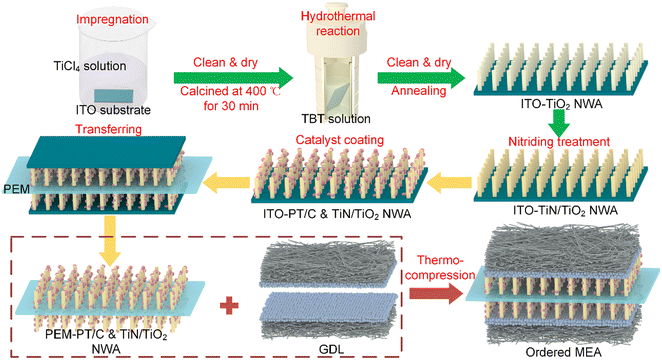
The TiN nanorod arrays were obtained through the nitridation reaction of TiO2. In situ growth of TiO2 on ITO substrates requires the preparation of a seed layer, which facilitates the growth of rod-shaped TiO2 on the substrate. In this study, TiCl4 was selected as the precursor solution, and the morphology control of the ordered catalyst layer support of TiN can be achieved by controlling the concentration of the TiCl4 solution in the precursor solution and the content of TBT and hydrochloric acid during the hydrothermal reaction.In the seed-assisted hydrothermal reaction, the array density of TiO2 is positively correlated with the concentration of TiCl4 solution. Fig. 1 illustrates the SEM images of TiO2 nanorod arrays grown from precursor solutions at various TiCl4 concentrations. As the concentration of TiCl4 increases from 0.05 mol L−1 to 0.20 mol L−1, the directional alignment of TiO2 array structure on ITO improves, the array density increases, and the diameter of the grown nanoscale TiO2 decreases. When the concentration of TiCl4 is 0.05 mol L−1, the TiO2 nanorods are dispersed in a clustered form on the surface of ITO, as shown in Fig. 1a1. Due to insufficient of growth sites, the nanorods tend to aggregate during the growth procedure, resulting in the generated TiO2 being unable to cover the ITO surface completely, as shown in Fig. 1a2. At a TiCl4 concentration of 0.10 mol L−1, TiO2 nanorods with a diameter of approximately 200 nm are grown on ITO. The alignment of the array is generally consistent, and suitable spacing between nanorods provides sufficient space for subsequent catalyst loading and facilitates efficient multi-phase channels for electrochemical reactions, as shown in Fig. 1b. When the TiCl4 concentration reaches 0.15 mol L−1, the ITO substrate is completely covered by TiO2 nanorods, and noticeable cracks are observed at low magnification. Although the nanorod diameter is consistent at this concentration, the density is too high to serve as a catalyst support, as shown in Fig. 1c. At a TiCl4 concentration of 0.20 mol L−1, the nanorod array becomes excessively dense, and numerous cracks are visible at low magnification, caused by stress concentration leading to fragmentation during cooling or cleaning processes, as shown in Fig. 1d. The overly dense seed distribution results in significant adhesion between nanorods, preventing further experiments. Additionally, the formation of bulk titanium dioxide can be observed, which would waste catalyst material and block multi-phase reaction channels. Therefore, a TiCl4 concentration of 0.10 mol L−1 is ultimately selected as the precursor solution for seed growth.
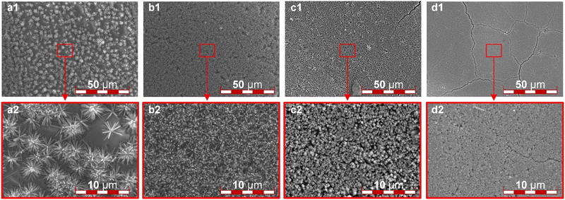 | ||
| Fig. 1 The SEM images of the TiO2 ordered array: (a) 0.05 mol L−1, (b) 0.10 mol L−1, (c) 0.15 mol L−1, and (d) 0.20 mol L−1 concentration of TiCl4 seed solution respectively. | ||
After determining the precursor solution concentration for seed formation, it is crucial to investigate the key parameters during the hydrothermal reaction. Next, the TiN nanorod array on the ITO surface after the nitridation reaction will be observed. The content of TBT in the hydrothermal reaction precursor greatly influences the morphology of the nanorod array, as shown in Fig. 2. When 0.5 mL of TBT solution was added to the precursor solution, due to the inadequate TBT content, the TiN array fails to cover the entire ITO surface, as illustrated in Fig. 2a1. Additionally, an insufficient nanorod array was obtained, and only discrete TiN clusters are formed, as shown in Fig. 2a2. By increasing the TBT content to 1.0 mL, a satisfactory TiN nanorod array is achieved. Furthermore, the TiN nanorods prepared under this condition exhibit uniform thickness, clear directional alignment, appropriate spacing distribution, and a remarkably smooth surface when observed at low magnification, as shown in Fig. 2b. When the TBT content is further increased to 1.5 mL, some bulk metal compounds start to appear on the ITO surface, as shown in Fig. 2c1, impeding water vapor transport and potentially leading to the rupture of the PEM. Meanwhile, the nanorod array becomes inconsistent in length and uneven in thickness, as illustrated in Fig. 2c2. At a TBT content of 2.0 mL, the prepared TiN completely loses its directional alignment. A large amount of bulk materials is distributed on the ITO surface, blocking the channels for material exchange, rendering it unsuitable as a catalyst support, as shown in Fig. 2d. It is evident that the TBT content in the hydrothermal reaction precursor solution is significantly correlated with the surface morphology of the TiN nanorod array. A higher TBT content initially enhances and then degrades the vertical alignment of TiN nanorods, along with more bulk metal compounds on the surface. Therefore, they are unfit as a catalyst support. So, we choose a TBT content of 1.0 mL to create an ordered catalyst support.
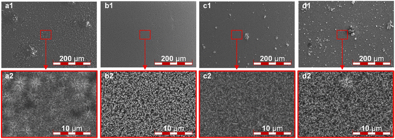 | ||
| Fig. 2 The SEM images of the TiN ordered array: the TBT content of (a) 0.5 ml; (b) 1.0 ml; (c) 1.5 ml; (d) 2.0 ml. | ||
During the hydrothermal reaction, hydrochloric acid acts as an inhibitor of TBT hydrolysis, so the ratio of water to hydrochloric acid in the solution has a significant effect on the uniformity and thickness of the whiskers, and only a suitable ratio can yield catalyst layer supports that meet the requirements. When the ratio of water to acid is 1![[thin space (1/6-em)]](https://www.rsc.org/images/entities/char_2009.gif) :
:![[thin space (1/6-em)]](https://www.rsc.org/images/entities/char_2009.gif) 2, the resulting nanorods are extremely small and exhibit poor uniformity, accompanied by noticeable agglomeration. Irregular spherical particles are observed to be irregularly distributed on the ITO surface, as shown in Fig. 3a. On the other hand, when the ratio of water to acid is 1
2, the resulting nanorods are extremely small and exhibit poor uniformity, accompanied by noticeable agglomeration. Irregular spherical particles are observed to be irregularly distributed on the ITO surface, as shown in Fig. 3a. On the other hand, when the ratio of water to acid is 1![[thin space (1/6-em)]](https://www.rsc.org/images/entities/char_2009.gif) :
:![[thin space (1/6-em)]](https://www.rsc.org/images/entities/char_2009.gif) 1, the whiskers exhibit a highly uniform and smooth surface distribution, with appropriate thickness and spacing, making it an ideal and ordered catalyst layer support, as illustrated in Fig. 3b. As the water content increases, the inhibitory effect of dilute hydrochloric acid on the hydrothermal reaction weakens. When the water-to-acid ratio is 2
1, the whiskers exhibit a highly uniform and smooth surface distribution, with appropriate thickness and spacing, making it an ideal and ordered catalyst layer support, as illustrated in Fig. 3b. As the water content increases, the inhibitory effect of dilute hydrochloric acid on the hydrothermal reaction weakens. When the water-to-acid ratio is 2![[thin space (1/6-em)]](https://www.rsc.org/images/entities/char_2009.gif) :
:![[thin space (1/6-em)]](https://www.rsc.org/images/entities/char_2009.gif) 1, a large number of irregular and large-scale aggregations appear on the ITO surface. Furthermore, at high magnification, the whiskers are observed to become very thick with minimal spacing, as shown in Fig. 3c. When the water-to-acid ratio is 3
1, a large number of irregular and large-scale aggregations appear on the ITO surface. Furthermore, at high magnification, the whiskers are observed to become very thick with minimal spacing, as shown in Fig. 3c. When the water-to-acid ratio is 3![[thin space (1/6-em)]](https://www.rsc.org/images/entities/char_2009.gif) :
:![[thin space (1/6-em)]](https://www.rsc.org/images/entities/char_2009.gif) 1, the ITO surface no longer possesses whiskers, it forms a highly dense coating with large spherical aggregations instead, as shown in Fig. 3d1. In observation under high magnification, the whiskers at the aggregation sites are extremely short and exhibit uneven thickness, rendering them unsuitable as catalyst supports, as illustrated in Fig. 3d2. Based on the findings, the final choice was a water-to-acid ratio of 1
1, the ITO surface no longer possesses whiskers, it forms a highly dense coating with large spherical aggregations instead, as shown in Fig. 3d1. In observation under high magnification, the whiskers at the aggregation sites are extremely short and exhibit uneven thickness, rendering them unsuitable as catalyst supports, as illustrated in Fig. 3d2. Based on the findings, the final choice was a water-to-acid ratio of 1![[thin space (1/6-em)]](https://www.rsc.org/images/entities/char_2009.gif) :
:![[thin space (1/6-em)]](https://www.rsc.org/images/entities/char_2009.gif) 1 to achieve a smooth surface morphology, moderate whisker thickness, and reasonable spacing.
1 to achieve a smooth surface morphology, moderate whisker thickness, and reasonable spacing.
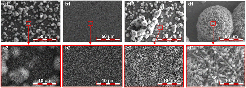 | ||
Fig. 3 The SEM images of the TiN ordered array: the ratios of water to hydrochloric acid in the hydrothermal reaction solution were (a) 1![[thin space (1/6-em)]](https://www.rsc.org/images/entities/char_2009.gif) : :![[thin space (1/6-em)]](https://www.rsc.org/images/entities/char_2009.gif) 2, (b) 1 2, (b) 1![[thin space (1/6-em)]](https://www.rsc.org/images/entities/char_2009.gif) : :![[thin space (1/6-em)]](https://www.rsc.org/images/entities/char_2009.gif) 1, (c) 2 1, (c) 2![[thin space (1/6-em)]](https://www.rsc.org/images/entities/char_2009.gif) : :![[thin space (1/6-em)]](https://www.rsc.org/images/entities/char_2009.gif) 1, and (d) 3 1, and (d) 3![[thin space (1/6-em)]](https://www.rsc.org/images/entities/char_2009.gif) : :![[thin space (1/6-em)]](https://www.rsc.org/images/entities/char_2009.gif) 1, respectively. 1, respectively. | ||
2.2 Nanoarray element composition determination
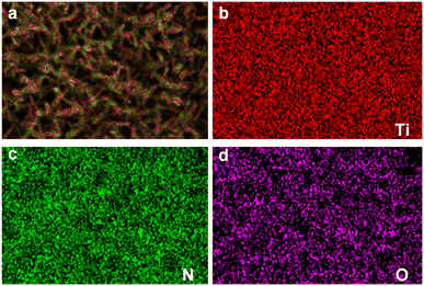
EDS tests were conducted on the samples to determine the composition of the product after the nitridation reaction, and the results are presented in Fig. 4. The surface of the samples exhibited clear detection of three elements: titanium (Ti), nitrogen (N), and oxygen (O). Titanium was identified as the predominant element, accounting for 64.27% of the mass and 35.67% of the atomic composition. Nitrogen was the second most abundant element, comprising 21.02% of the mass and 39.89% of the atomic composition. Additionally, a residual amount of oxygen was observed, constituting 14.71% of the mass and 24.44% of the atomic composition. These findings provide compelling evidence for the successful conversion of whiskers into TiN through the nitridation reaction. However, the presence of oxygen suggests that the nitridation reaction may not have reached complete conversion, resulting in a core–shell structure with an outer layer of TiN and an inner layer of TiO2. Furthermore, the thinness of the nanorod array necessitates consideration of potential interference from the quartz glass substrate during EDS analysis. In conclusion, the EDS experiment confirms the synthesis of uniformly distributed TiN nanorod arrays, which hold promise as catalyst supports within the internal region of the MEA for PEMFCs.2.3 Fabrication results of double-side ordered MEA
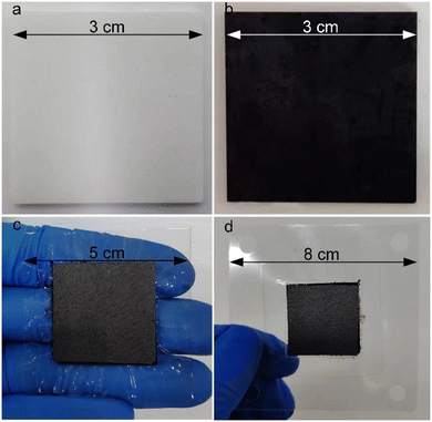
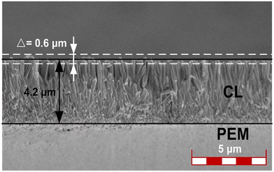
The photographs showcasing the manufacturing process of the ordered membrane electrode assembly (MEA) are presented in Fig. 5. Initially, the desired morphology, size, and spacing of a TiO2 nanorod array were synthesized on a 3 × 3 cm2 indium tin oxide (ITO) substrate using a seed-assisted hydrothermal reaction as shown in Fig. 5a. The resulting ITO surface exhibited a characteristic white color, attributed to the physical properties of TiO2. Subsequently, the TiO2@ITO sample was subjected to a nitridation process within a tubular furnace under an ammonia atmosphere. Consequently, the ITO surface transformed into a distinct black color, predominantly emanating from the TiN nanorod array's properties (Fig. 5b). In the process of ultrasonic spraying, isopropanol was used as the dispersant of the catalyst, and Nafion solution was used as the proton conductor. The volume ratio of isopropanol to water was 5, the mass ratio of Nafion solution to PtC was 0.7, and the PtC content in the slurry was 2 mg ml−1. The four components were added to the vessel in the order of PtC, water, isopropanol, and Nafion solution, and then ultrasonically mixed for 1 h in an ice bath to form the ultrasonic spray coating slurry. At this stage, the platinum-based catalyst was effectively loaded onto the black surface using ultrasound-assisted spray coating to ensure their complete infiltration into the array's interior. In contrast to the GDE configuration, the catalyst does not get trapped in the micropores of the carbon paper during the coating and transfer process. Instead, it is evenly distributed on both sides of the PEM with minimal waste, leading to a high level of catalyst utilization efficiency in this approach. Due to the much higher diffusion of hydrogen gas at the anode than oxygen gas at the cathode, in this study, by controlling the ultrasonic spray time and nozzle speed, the platinum loading of the cathode was determined to be 0.2 mg cm−2, while that of the anode was 0.1 mg cm−2. It should be noted that due to the weak bonding between TiN and ITO, and the susceptibility of thin TiN layers to fracture, the spray coating process required the adjustment of the load-carrying airflow to its minimum. Subsequently, two catalytically-loaded ITO substrates sandwiched a 5 × 5 cm2 proton exchange membrane (PEM) during a thermal transfer press operation, resulting in the preparation of the catalyst-coated membrane (CCM). Carbon papers were then placed on both sides of the CCM to form a complete MEA (Fig. 5c). Finally, to mitigate moisture-induced deformation, the prepared MEA underwent PET encapsulation before final testing. The resulting ordered MEA exhibited a total area of 8 × 8 cm2, with an effective active area of 3 × 3 cm2, as shown in Fig. 5d.We sectioned the CCM after transfer hot-pressing to investigate the morphology of the TiN nanorod array in the MEA by SEM, as depicted in Fig. 6. The cross-sectional image demonstrates that the TiN nanorod array was entirely transferred to the PEM and retained its original shape well. The CL had a thickness of 4.2 μm, and the TiN nanorod array displayed good orientation. Moreover, the upper and lower surfaces of the ordered CL were smooth, with a flatness variation of only 0.6 μm, which could not only ensure a snug fit with the PEM without causing puncture damage, but also diminish the dead zone between the CL and diffusion layer, enhancing the expulsion of water. Owing to the ultrasonic spraying before transfer, the catalyst in CL exhibited a denser feature near the PEM side, which was favorable to exploit the catalyst to a greater degree.
2.4 Electrochemical properties of double-side ordered MEA
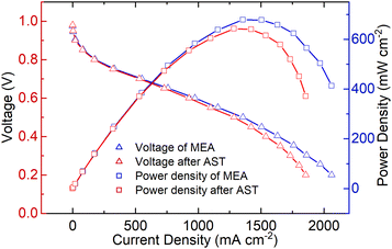
The performance of the ordered MEA can be evaluated by the polarization curve and the power density curve, as shown in Fig. 7. The polarization curve reveals how the voltage changes with the current density, whereas the power density curve demonstrates how the output power changes with the current density. The fabricated MEA demonstrates an initial performance that achieves a peak power density of 678.30 mW cm−2. When the output voltage reaches 0.6 V, it can be considered as the working voltage of the MEA. Due to the larger reactive surface area and superior catalyst dispersion, the working current density remains stable at 971.62 mA cm−2, with an output power density of 583.08 mW cm−2. During the operation of fuel cells, high-power operation is inevitable, which involves high current density but lower voltage. In such cases, water flooding and electrode material corrosion are prone to occur. However, thanks to the efficient mass transfer channels provided by the TiN nanorod arrays, the ordered MEA fabricated showed a nearly linear relationship between the increased current density and output voltage, without experiencing severe voltage decay. This observation indicates that the internal membrane electrode can still maintain a favorable oxygen reduction reaction (ORR) process and efficient removal of product water.In this study, we employed the chemical accelerated stress test (AST) for MEAs provided by the U.S. Department of Energy (DOE) to investigate the durability of the ordered MEAs fabricated. The electrochemical performance of the MEAs was also evaluated. After AST operation, the performance of the membrane electrode can decline due to various factors such as chemical degradation of the proton exchange membrane, catalyst deactivation, and carbon support corrosion. As shown in Fig. 7, the performance of the membrane electrode in the low current density region showed a minimal decline, while a significant drop was observed in the high current density region. This discrepancy can be attributed to the dominant influence of activation polarization overpotential in the low current density region, whereas the high current density region is mainly affected by the ohmic polarization overpotential and concentration polarization overpotential. The ordered membrane electrode exhibited a 4.8% decrease in output performance at a working voltage of 0.6 V. However, as the current density increased, the decline in the membrane electrode performance became more pronounced, with a relative decrease of 7% in the MEA current density when the output voltage reached 0.3 V. Simultaneously, the peak power density decreased to 642.13 mW cm−2, and there was a noticeable leftward shift in the peak power inflection point. Due to its exceptional chemical stability and excellent corrosion resistance and conductivity, TiN has been shown in multiple studies to exhibit outstanding corrosion resistance when structured in nanoscale arrays.44–46 It can operate stably in acidic, neutral, and alkaline electrolytes for extended periods without altering its morphology and structure. Therefore, we believe that even in the presence of an ordered carrier, prolonged operation at high current densities may lead to the loss of catalytic activity and dispersion, causing some loosely attached catalysts on TiN to aggregate, resulting in increased ohmic polarization and concentration polarization overpotentials.
To comprehensively evaluate our double-side ordered MEA based on TiN nanorod arrays, we conducted extensive research on current typical PEMFC electrode structures and preparation methods. Table 1 showcases various MEA structures prepared using different methods. The MEAs with disordered structures typically necessitate higher platinum loading to attain optimal performance, as depicted in Table 1. This is attributed to their internal multiphase reaction channels being in a disordered state, resulting in generally lower platinum utilization. The MEAs prepared through ultrasonic spraying and transfer printing exhibit similar performance but display distinct characteristics. Ultrasonic spraying, owing to its superior catalyst dispersion, demonstrates exceptional working voltage output performance, while transfer printing exhibits higher peak power. Interestingly, ultrasonic spraying and active screen plasma nitriding processing show similar performance, but the former is obviously faster and cheaper in comparison. Although the cathode single-sided ordered MEA can achieve performance similar to disordered structures with lower catalyst content, there still exists a discernible gap. It can be seen from the comparison that the cathode ordering has a significant improvement on the performance of the MEA, which can achieve a similar performance to the conventional MEA with only half of the platinum loading. This indicates that the ordered structure has a promoting effect on the ORR, which benefits from its provision of good mass transfer and water drainage channels. By comparing the bilateral and cathode unilateral ordered structures, it can be found that the performance of the membrane electrode has been further improved. This is because the fuel cell involves two half-reactions at the anode and cathode, and only when both sides are at a high level can a better cell performance be obtained. Therefore, it can be proved that the anode ordered structure can also provide more reaction sites for the hydrogen oxidation reaction.
| MEA structural | Preparation process | Pt load (mg cm−2) | Peak power (mW cm−2) | Current density@0.6 V (mA cm−2) | Ref. |
|---|---|---|---|---|---|
| Disordered | Ultrasonic spraying | 0.4 | 695 | 1100 | 40 |
| Disordered | Transfer printing | 0.5 | 920 | 540 | 41 |
| Cathode-ordered | Ultrasonic spraying | 0.2 | 538.33 | 819.57 | 42 |
| Cathode-ordered | Active screen plasma nitriding | 0.19 | 640 | 900 | 43 |
| Doubleside-ordered | Ultrasonic spraying & decal transfer | 0.2 | 678.30 | 917.62 | This work |
In this study, we utilized a combination of ultrasonic spraying and transfer printing techniques to create a double-side ordered MEA utilizing TiN nanorod arrays. This innovative approach resulted in output performance comparable to that of traditional methods but with only half the platinum loading. The fabrication of double-side ordered MEAs through ultrasonic spraying and transfer printing showcases a promising, efficient, stable, and low-platinum solution.
3 Conclusions
This paper presents a novel double-side ordered MEA for PEMFCs based on TiN nanorod arrays. The arrays were synthesized by a seed-assisted hydrothermal reaction and a subsequent nitriding treatment, and then transferred to both sides of the PEM by using ultrasonic spraying and transfer printing. The morphology and density of the TiN nanorod arrays were controlled by adjusting the concentration of TiCl4 in the seed solution, the content of TBT and the ratio of water to hydrochloric acid in the hydrothermal reaction solution. The TiN nanorod arrays exhibited high electrical conductivity, corrosion resistance, and catalytic activity as catalyst supports for PEMFCs. The ordered structure of the catalyst layers provided well-defined channels for reactant gas diffusion and product water removal, as well as a large surface area for catalyst loading and reaction sites. The fabricated ordered-MEA showed high performance and durability under various operating conditions. The peak power density reached 678.30 mW cm−2, and the working current density remained stable at 971.62 mA cm−2 at a working voltage of 0.6 V. After AST operation, the ordered-MEA exhibited a relative decrease of 4.8% in output performance at a working voltage.This study provides a new approach for developing high-performance, low-platinum MEAs. In future work, we will further optimize the membrane electrode structure design and preparation process with the goal of high power density through a combination of MEA half-reaction simulation and experimental verification. Additionally, we will conduct research on high-power density single-cell packaged fuel cells.
4 Experimental section
4.1 Structure of double-side ordered MEA
The MEA is an essential component of proton exchange membrane fuel cells (PEMFCs) that can efficiently convert the chemical energy from hydrogen and oxygen into electricity. Here, we present a novel double-side ordered MEA based on TiN nanorod arrays. These nanorod arrays are prepared by seed-assisted hydrothermal reaction and nitriding treatment. Meanwhile, the catalyst loading is achieved through the ultrasonic spraying method. The structure of the double-side ordered MEA is illustrated in Fig. 8a, and it adopts a seven-in-one configuration, comprising the anode gas diffusion layer (AGDL), anode micro-porous layer, anode ordered catalyst layer (ACL), proton exchange membrane (PEM), ordered cathode catalyst layer (CCL), cathode micro-porous layer, and cathode gas diffusion layer (CGDL). Among these layers, the catalyst layer plays a crucial role in facilitating the major electrochemical reactions within the fuel cell. It requires materials that are corrosion-resistant, have low impedance, and exhibit efficient channels to ensure unobstructed mass transport and timely removal of product water. To fulfill these requirements, we develop ordered catalyst layers composed of TiN nanorod arrays that are directly constructed on the substrate using a hydrothermal reaction and then transferred to both sides of the PEM through the transfer printing process. The TiN arrays are oriented perpendicularly to the micro-porous layer and PEM. This ordered catalyst layer structure provides additional reaction sites for oxygen, protons and electrons, thus efficiently facilitating the removal of generated water. These features contribute to the enhanced promotion of oxygen reduction reaction (ORR).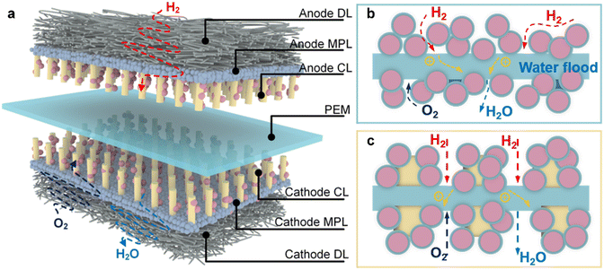 | ||
| Fig. 8 (a) Structure of double-side ordered MEA structure, and working principle of (b) traditional MEA and (c) ordered MEA. | ||
4.2 Working principle
As for conventional MEAs, the catalyst particles are dispersed in a disordered manner on both sides of the PEM, leading to tortuous or even blocked transport channels, resulting in detrimental factors such as water flooding, polarization corrosion and catalyst agglomeration, as illustrated in Fig. 8b. The working principle of the ordered MEA is shown in Fig. 8c. Due to the small molecular weight of hydrogen, it can easily diffuse into the anode catalytic layer. Therefore, the structured anode catalytic layer can provide a large number of catalytic sites, promoting the decomposition of hydrogen into protons and electrons. When the protons are conducted to the cathode through Nafion and PEM, the electrons reach the cathode through the external circuit, and combine with oxygen in the reduction reaction to form water. The ordered nanorod TiN arrays offer an optimal environment for mass transfer and provide a large reaction surface area for the ORR, resolving the issues associated with the conventional MEA's disordered structure. Furthermore, thanks to TiN's corrosion resistance and low electrical resistance properties, the electrode's vulnerability to damage from high potentials and strong acids is effectively reduced. Consequently, the multi-phase mass transfer channels remain unobstructed. Moreover, the catalyst is loaded by ultrasonic spraying and decal transferring, so that the catalyst concentration increases from the GDL to PEM gradually, guaranteeing a high catalyst utilization.The function and advantages of the TiN double-side ordered MEA are mainly reflected in its highly ordered channel structure, which can effectively promote mass transfer and water management, while maintaining high catalytic activity and stability. Firstly, the channel structure of the double-side ordered MEA can increase the permeability of hydrogen and air, thereby improving the utilization of reactants and the performance of the cell. Due to the low mass transfer resistance of the TiN nanorod array channel structure, the gas diffusion ability can be significantly improved. Secondly, due to the radial capillary force and low surface tension of the channel structure of the double-side ordered MEA, the water discharge speed can be significantly increased, thus avoiding water accumulation and blockage, and improving the stability and durability of the cell.
The proposed ordered-MEA offers several benefits, including: (1) enhanced mass transport through the implementation of structured anodes and cathodes, (2) increased durability attributed to the corrosion resistance and low electrical resistance properties of TiN, and (3) improved catalyst utilization resulting from the gradient distribution of catalyst concentration.
4.3 Fabrication process of double-side ordered MEA
The preparation process of the double-side ordered MEA can be illustrated as shown in Fig. 9; the green, yellow and red arrows represent the fabrication process of nanorod arrays, the loading and transfer process of catalysts, and the manufacturing process of the ordered-MEA, respectively. Hence, the fabrication process of the double-side ordered MEA can be mainly divided into three parts: preparation of an ordered carrier for the catalyst layer, ultrasonic spraying and decal transferring of the catalyst, and thermal pressing encapsulation of the membrane electrode. These correspond to the upper, middle, and lower sections of Fig. 9.The key process in the fabrication of the double-side ordered MEA lies in the rational preparation of TiN nanorod arrays. The nanorod arrays on ITO were synthesized using a seed-assisted hydrothermal method. The seed-assisted hydrothermal process is rather simple and does not require complex conditions to obtain products with complete crystalline shape, uniform particle size distribution and good dispersion. For the fabrication of TiN nanorod arrays, TiCl4, tetrabutyl titanate (TBT), concentrated hydrochloric acid, ethanol and isopropanol were purchased from HUSHI® (Shanghai, China). All chemicals were of analytical grade and were used as received without further purification. A detailed description of the fabrication process will be provided, which consists of 3 procedures corresponding to the green arrows in Fig. 9. The specific steps are as follows:
Step 1-Synthesis of seed crystals: a 3 cm × 3 cm ITO substrate was subjected to ultrasonic cleaning in a solution containing deionized water, ethanol, and acetone (in a volume ratio of 1![[thin space (1/6-em)]](https://www.rsc.org/images/entities/char_2009.gif) :
:![[thin space (1/6-em)]](https://www.rsc.org/images/entities/char_2009.gif) 1
1![[thin space (1/6-em)]](https://www.rsc.org/images/entities/char_2009.gif) :
:![[thin space (1/6-em)]](https://www.rsc.org/images/entities/char_2009.gif) 1) for 20 min. Subsequently, the ITO substrate was heated to 120 °C and dried for another 20 min. To ensure that only the conducting layer remains exposed, the non-conductive surface of the cleaned ITO was carefully sealed with polytetrafluoroethylene (PTFE) tape. Then, the cleaned ITO glass substrate was immersed in a TiCl4 chloride aqueous solution and heated at 70 °C for 15 minutes in a water bath. During this process, TiCl4 underwent hydrolysis reaction and formed TiO2 seeds on the surface of ITO. The corresponding chemical reaction can be described as
1) for 20 min. Subsequently, the ITO substrate was heated to 120 °C and dried for another 20 min. To ensure that only the conducting layer remains exposed, the non-conductive surface of the cleaned ITO was carefully sealed with polytetrafluoroethylene (PTFE) tape. Then, the cleaned ITO glass substrate was immersed in a TiCl4 chloride aqueous solution and heated at 70 °C for 15 minutes in a water bath. During this process, TiCl4 underwent hydrolysis reaction and formed TiO2 seeds on the surface of ITO. The corresponding chemical reaction can be described as
| TiCl4 + 2H2O ≜ TiO2 + 4HCl | (1) |
Step 2-Seed assisted hydrothermal reaction: to prepare the hydrothermal reaction precursor, a TBT solution with a volume ranging from 0.5 to 2.0 ml was added to a mixture of 20 mL concentrated hydrochloric acid and 20 mL deionized water. The resulting solution was stirred for a period of 15 min. Subsequently, the mixture along with the ITO substrate coated with TiO2 seeds was transferred into a 100 mL Teflon-lined stainless-steel autoclave. During the transfer, it was crucial to position the conducting layer with seeds facing downward to prevent undesired TiO2 deposition, which could lead to changes in whisker morphology or stomatal blockage. The hydrothermal treatment commenced with heating at a rate of 5 °C min−1 and was maintained at a temperature of 170 °C for a duration of 9 hours. The ensuing chemical reactions occurring during this step are
| Ti(O–C4H9)4 + 2H2O = TiO2 + 4CH3(CH2)3OH | (2) |
Step 3-Nitriding treatment: the last step involves nitridation of the TiO2 nanorod arrays generated by the seed-assisted hydrothermal reaction to convert the product into TiN. The nitridation process was carried out by suspending the synthesized TiO2 nanorod arrays in an alumina boat and placing it in a tube furnace. The temperature was raised to 450 °C under a nitrogen atmosphere, followed by switching the gas source to ammonia. The sample was then heated to 850 °C and kept at that temperature for 3 hours while maintaining an ammonia atmosphere. Subsequently, the gas source was switched back to nitrogen and the temperature was gradually cooled down to room temperature. The chemical reaction equation during this process is
| 6TiO2 + 8NH3 ≜ 6TiN + 12H2O + N2 | (3) |
4.4 Characterization tests
To characterize the performance of the fabricated double-side ordered MEA, the following tests were conducted. The single fuel cell is evaluated at ambient pressure and the temperature was set to constant. The reactants can be fed into the fuel cell at a fixed flow rate to meet the reaction requirements.Conflicts of interest
There are no conflicts to declare.Acknowledgements
The authors acknowledge the financial support from the National Natural Science Foundation of China (U1809220), Key Research and Development Program of Zhejiang Province (2022C01113), and Key Research and Fundamental Research Funds for the Central Universities (2022FZZX01-06).References
- M. K. Debe, Electrocatalyst approaches and challenges for automotive fuel cells, Nature, 2012, 486, 43–51 CrossRef CAS.
- J. Fan, M. Chen, Z. Zhao, Z. Zhang, S. Ye, S. Xu, H. Wang and H. Li, Bridging the gap between highly active oxygen reduction reaction catalysts and effective catalyst layers for proton exchange membrane fuel cells, Nat. Energy, 2021, 6, 475–486 CrossRef CAS.
- J. Hou, M. Yang, L. Zhou, X. Yan, C. Ke and J. Zhang, Transforming materials into practical automotive lithium-ion batteries, Adv. Mater. Technol., 2021, 6, 2100152 CrossRef CAS.
- D. Xue and J.-N. Zhang, Recent progress of antipoisoning catalytic materials for high temperature proton exchange membrane fuel cells doped with phosphoric acid, Ind. Chem. Mater., 2024 10.1039/D3IM00101F.
- J. Han, J. Bian and C. Sun, Recent advances in single-atom electrocatalysts for oxygen reduction reaction, Research, 2020, 2020, 9512763 CAS.
- X. Min, J. Xia, X. Zhang and K. Ding, Study on the output performance of the proton exchange membrane fuel cells using print circuit board, Renewable Energy, 2022, 197, 359–370 CrossRef CAS.
- F. Calili-Cankir, M. S. Ismail, D. B. Ingham, K. J. Hughes, L. Ma and M. Pourkashanian, Air-breathing polymer electrolyte fuel cells: A review, Renewable Energy, 2023, 213, 86–108 CrossRef CAS.
- T. Zhuang, L. Yuan, Q. Wan, Y. Zhang, J. Li, L. Zhang, J. Hou, C. Ke and J. Zhang, Investigation on a novel direct liquid fuel cell feeding on oxalyl dihydrazide, J. Electrochem. Soc., 2021, 168, 034515 CrossRef CAS.
- J. Hou, S. Qu, M. Yang and J. Zhang, Materials and electrode engineering of high capacity anodes in lithium ion batteries, J. Power Sources, 2020, 450, 227697 CrossRef CAS.
- K. Lim, C. Kim, R. Park, A. Alam and H. Ju, Enhancing PEMFC performance through orifice-shaped cathode flow field designs: A multiscale, multiphase simulation study on oxygen supply and water removal, Chem. Eng. J., 2023, 475, 146147 CrossRef CAS.
- M. Janssen, P. Weber and M. Oezaslan, Recent advances of various Pt-based catalysts for oxygen reduction reaction (ORR) in polymer electrolyte membrane fuel cells (PEMFCs), Curr. Opin. Electrochem., 2023, 40, 101337 CrossRef CAS.
- S. Liu, S. Hua, R. Lin, H. Wang, X. Cai and W. Ji, Improving the performance and durability of low Pt-loaded MEAs by adjusting the distribution positions of Pt particles in cathode catalyst layer, Energy, 2022, 253, 124201 CrossRef CAS.
- A. Kongkanand, N. P. Subramanian, Y. Yu, Z. Liu, H. Igarashi and D. A. Muller, Achieving high-power PEM fuel cell performance with an ultralow-Pt-content core–shell catalyst, ACS Catal., 2016, 6, 1578–1583 CrossRef CAS.
- M. K. Debe, S. M. Hendricks, G. D. Vernstrom, M. Meyers, M. Brostrom, M. Stephens, Q. Chan, J. Willey, M. Hamden, C. K. Mittelsteadt, C. B. Capuano, K. E. Ayers and E. B. Anderson, Initial performance and durability of ultra-low loaded NSTF electrodes for PEM electrolyzers, J. Electrochem. Soc., 2012, 159, K165–K176 CrossRef CAS.
- D. F. Van Der Vliet, C. Wang, D. Tripkovic, D. Strmcnik, X. F. Zhang, M. K. Debe, R. T. Atanasoski, N. M. Markovic and V. R. Stamenkovic, Mesostructured thin films as electrocatalysts with tunable composition and surface morphology, Nat. Mater., 2012, 11, 1051–1058 CrossRef CAS.
- G. Liu, F. Ye, L. Xiong, J. Lee, L. Wang, X. Li, J. Li, J. K. Lee and W. Yang, Cathode catalyst layer with nanofiber microstructure for direct methanol fuel cells, Energy Convers. Manage., 2020, 218, 113013 CrossRef CAS.
- G. Wang, L. Zou, Q. Huang, Z. Zou and H. Yang, Multidimensional nanostructured membrane electrode assemblies for proton exchange membrane fuel cell applications, J. Mater. Chem. A, 2019, 7, 9447–9477 RSC.
- R. Kumar, M. Mooste, Z. Ahmed, S. Akula, I. Zekker, M. Marandi, M. Käärik, J. Leis, A. Kikas, A. Treshchalov, M. Otsus, J. Aruväli, V. Kisand, A. Tamm and K. Tammeveski, Highly active ZIF-8@CNT composite catalysts as cathode materials for anion exchange membrane fuel cells, Ind. Chem. Mater., 2023, 1, 526–541 RSC.
- S. Shahgaldi and J. Hamelin, Stability study of ultra-low Pt thin film on TiO2–C core–shell structure and TiO2 encapsulated in carbon nanospheres as cathode catalyst in PEMFC, Fuel, 2015, 150, 645–655 CrossRef CAS.
- M. Tan, W. Zhang, H. Liu, J. Zhang, Z. Guo, Q. Ma, Q. Xu, K. Hooshyari and H. Su, Revolutionizing high-temperature polymer electrolyte membrane fuel cells: Unleashing superior performance with vertically aligned TiO2 nanorods supporting ordered catalyst layer featuring Pt nanowires, Fuel, 2024, 357, 130084 CrossRef CAS.
- V. Lee, V. Berejnov, M. West, S. Kundu, D. Susac, J. Stumper, R. T. Atanasoski, M. Debe and A. P. Hitchcock, Scanning transmission X-ray microscopy of nano structured thin film catalysts for proton-exchange-membrane fuel cells, J. Power Sources, 2014, 263, 163–174 CrossRef CAS.
- A. Kongkanand, J. Zhang, Z. Liu, Y.-H. Lai, P. Sinha, E. L. Thompson and R. Makharia, Degradation of PEMFC observed on NSTF electrodes, J. Electrochem. Soc., 2014, 161, F744 CrossRef CAS.
- G. Yang, S. Komini Babu, W. P. R. Liyanage, U. Martinez, D. Routkevitch, R. Mukundan, R. L. Borup, D. A. Cullen and J. S. Spendelow, Coaxial nanowire electrodes enable exceptional fuel cell durability, Adv. Mater., 2023, 35, 2301264 CrossRef CAS PubMed.
- H. Cho, S. Moon Kim, Y. Sik Kang, J. Kim, S. Jang, M. Kim, H. Park, J. Won Bang, S. Seo, K.-Y. Suh, Y.-E. Sung and M. Choi, Multiplex lithography for multilevel multiscale architectures and its application to polymer electrolyte membrane fuel cell, Nat. Commun., 2015, 6, 8484 CrossRef CAS PubMed.
- Z. Lu, S. Yao, Y. Dong, D. Wu, H. Pan, X. Huang, T. Wang, Z. Sun and X. Chen, Earth-abundant coal-derived carbon nanotube/carbon composites as efficient bifunctional oxygen electrocatalysts for rechargeable zinc-air batteries, J. Energy Chem., 2021, 56, 87–97 CrossRef CAS.
- S. Du, Recent advances in electrode design based on one-dimensional nanostructure arrays for proton exchange membrane fuel cell applications, Engineering, 2021, 7, 33–49 CrossRef CAS.
- C. Zhang, H. Yu, L. Fu, Y. Xiao, Y. Gao, Y. Li, Y. Zeng, J. Jia, B. Yi and Z. Shao, An oriented ultrathin catalyst layer derived from high conductive TiO2 nanotube for polymer electrolyte membrane fuel cell, Electrochim. Acta, 2015, 153, 361–369 CrossRef CAS.
- S. Jiang, B. Yi, C. Zhang, S. Liu, H. Yu and Z. Shao, Vertically aligned carbon-coated titanium dioxide nanorod arrays on carbon paper with low platinum for proton exchange membrane fuel cells, J. Power Sources, 2015, 276, 80–88 CrossRef CAS.
- Z.-Z. Jiang, Z.-B. Wang, Y.-Y. Chu, D.-M. Gu and G.-P. Yin, Carbon riveted microcapsule Pt/MWCNTs-TiO2 catalyst prepared by in situ carbonized glucose with ultrahigh stability for proton exchange membrane fuel cell, Energy Environ. Sci., 2011, 4, 2558–2566 RSC.
- M. Hezarjaribi, M. Jahanshahi, A. Rahimpour and M. Yaldagard, Gas diffusion electrode based on electrospun Pani/CNF nanofibers hybrid for proton exchange membrane fuel cells (PEMFC) applications, Appl. Surf. Sci., 2014, 295, 144–149 CrossRef CAS.
- H. Tang, S. Wang, M. Pan, S. P. Jiang and Y. Ruan, Performance of direct methanol fuel cells prepared by hot-pressed MEA and catalyst-coated membrane (CCM), Electrochim. Acta, 2007, 52, 3714–3718 CrossRef CAS.
- Y. Wang, L. Zheng, G. Han, L. Lu, M. Wang, J. Li and X. Wang, A novel multi-porous and hydrophilic anode diffusion layer for DMFC, Int. J. Hydrogen Energy, 2014, 39, 19132–19139 CrossRef CAS.
- C.-Y. Liu and C.-C. Sung, A review of the performance and analysis of proton exchange membrane fuel cell membrane electrode assemblies, J. Power Sources, 2012, 220, 348–353 CrossRef CAS.
- F. L. Deschamps, J. G. Mahy, A. F. Léonard, S. D. Lambert, A. Dewandre, B. Scheid and N. Job, A practical method to characterize proton exchange membrane fuel cell catalyst layer topography: Application to two coating techniques and two carbon supports, Thin Solid Films, 2020, 695, 137751 CrossRef CAS.
- M. Stähler, A. Stähler, F. Scheepers, M. Carmo and D. Stolten, A completely slot die coated membrane electrode assembly, Int. J. Hydrogen Energy, 2019, 44, 7053–7058 CrossRef.
- J. Zhao, S. Shahgaldi, A. Ozden, I. E. Alaefour, X. Li and F. Hamdullahpur, Effect of catalyst deposition on electrode structure, mass transport and performance of polymer electrolyte membrane fuel cells, Appl. Energy, 2019, 255, 113802 CrossRef CAS.
- I.-S. Park, W. Li and A. Manthiram, Fabrication of catalyst-coated membrane-electrode assemblies by doctor blade method and their performance in fuel cells, J. Power Sources, 2010, 195, 7078–7082 CrossRef CAS.
- C. Lee, W. J. M. Kort-Kamp, H. Yu, D. A. Cullen, B. M. Patterson, T. A. Arman, S. Komini Babu, R. Mukundan, R. L. Borup and J. S. Spendelow, Grooved electrodes for high-power-density fuel cells, Nat. Energy, 2023, 8, 685–694 CrossRef CAS.
- M. B. Sassin, Y. Garsany, B. D. Gould and K. E. Swider-Lyons, Fabrication method for laboratory-scale high-performance membrane electrode assemblies for fuel cells, Anal. Chem., 2017, 89, 511–518 CrossRef CAS PubMed.
- B. G. Pollet, A novel method for preparing PEMFC electrodes by the ultrasonic and sonoelectrochemical techniques, Electrochem. Commun., 2009, 11, 1445–1448 CrossRef CAS.
- S. Shahgaldi, I. Alaefour, G. Unsworth and X. Li, Development of a low temperature decal transfer method for the fabrication of proton exchange membrane fuel cells, Int. J. Hydrogen Energy, 2017, 42, 11813–11822 CrossRef CAS.
- L. Xuan, Y. Wang, J. Lan, K. Tao, C. Zhou and D. Mei, Development of cathode ordered membrane electrode assembly based on TiO2 nanowire array and ultrasonic spraying, Energy, 2023, 264, 126243 CrossRef CAS.
- P. Mardle, X. Ji, J. Wu, S. Guan, H. Dong and S. Du, Thin film electrodes from Pt nanorods supported on aligned N-CNTs for proton exchange membrane fuel cells, Appl. Catal., B, 2020, 260, 118031 CrossRef CAS.
- Y.-J. Jen, T.-L. Chan, B.-H. Liao, Z.-X. Li, W.-C. Liu and M.-Y. Cong, Tunable plasmonic resonances in TiN nanorod arrays, Coatings, 2019, 9, 863 CrossRef CAS.
- Y.-J. Jen, W.-C. Wang, K.-L. Wu and M.-J. Lin, Extinction properties of obliquely deposited TiN nanorod arrays, Coatings, 2018, 8, 465 CrossRef.
- R.-Q. Liu, F. Jin, M. Gu, D.-W. Zhang, L.-L. He, W.-X. Liu, W.-F. Zhu, K. Xie, J.-Y. Wu, Y.-R. Liu, W.-W. Yang, X.-J. Lin, L. Shi, X.-M. Feng, Z. Hou, J.-G. Zhou and Y.-W. Ma, Titanium nitride nanorod array/carbon cloth as flexible integrated host for highly stable lithium–sulfur batteries, Rare Met., 2023, 42, 4115–4127 CrossRef CAS.
| This journal is © Institute of Process Engineering of CAS 2024 |

