 Open Access Article
Creative Commons Attribution 3.0 Unported Licence
Effects of N2 plasma modification on the surface properties and electrochemical performance of Ni foam electrodes for double-chamber microbial fuel cells
Mozhgan
Gholami-Kermanshahi
a,
Ming-Cheng
Lee
b,
Günther
Lange
a and
Shih-Hang
Chang
 *b
*b
aGroup for Metallic and Composite Materials, TU Ilmenau, Gustav-Kirchhoff-Str. 6, 98693 Ilmenau, Germany
bDepartment of Chemical and Materials Engineering, National I-Lan University, I-Lan 260, Taiwan. E-mail: shchang@niu.edu.tw
First published on 22nd May 2024
Abstract
This study assessed the feasibility of using a plasma-modified Ni foam as an anode to improve the electrochemical performance of double-chamber microbial fuel cells (MFCs). Scanning electron microscopy results showed that Ni foam exhibited an open cellular structure and rough surface morphology, providing a large contact area between bacteria and anodes in the MFCs. N2 plasma modification did not influence the surface morphology of the Ni foam, whereas the hydrophobic surfaces of the Ni foam became highly hydrophilic. X-ray photoelectron spectrometer results revealed that Ni–N and NH3 functional groups, formed on the surface of the Ni foam during the N2 plasma modification, were responsible for its highly hydrophilic surface. Electrochemical measurements demonstrated that the highest power density of the MFC configured with an unmodified Ni foam anode electrode (166.9 mW m−2) was much higher than those of the MFCs configured with dense Ni rod (5.1 mW m−2) or graphite rod (29.5 mW m−2) anodes because Ni foam combined the advantages of an open cellular structure and good electrical conductivity. The highest power density of MFC configured with Ni foam was further improved to 247.1 mW m−2 after 60 min N2 plasma treatment owing to the high hydrophilicity of the N2 plasma-modified Ni foam electrodes, which facilitated bacteria adhesion and biofilm formation.
Introduction
Renewable energy sources, such as solar power, geothermal energy, hydropower, wind energy, and bioenergy, are promising candidates for electricity generation that can restock themselves within human lifetime. Fuel cells and solar power systems play vital roles in ensuring a cleaner and greener environment and in reducing the greenhouse gas footprint by limiting fossil fuel consumption for electricity generation. However, the limitations of renewable energy technologies have led to challenges owing to their low efficiency, high production costs, and low overall profitability. Microbial fuel cells (MFCs) have emerged as a promising technology for providing electrical energy using wastewater as a substrate; they can be used in wastewater treatment plants to decompose organic matter in wastewater to generate electricity, remove pollutants, and produce clean water as a byproduct.1–4 MFCs in wastewater treatment plants influence energy savings and reduce greenhouse gas emissions. MFCs are more energy-efficient alternatives to traditional wastewater treatment plants because they offset the energy needs of treatment plants by generating electricity from the organic matter in wastewater.5 The main advantage of MFCs over conventional fuel cells is their use of a wide range of organic and inorganic matter, such as organic waste and soil sediments, as sources of fuel production in anode chambers. Unlike conventional fuel cells, MFCs can operate at ambient temperature and atmospheric pressure, under neutral pH conditions.Although MFCs are considered a potential avenue for reducing the over-reliance on fossil fuel-based electricity, limitations such as low power generation, low microbe growth rates, high membrane costs, and the inability to generate large-scale electricity for industrially relevant capacities have slowed the advancement of MFC development.6 One of the main challenges contributing to the low electrode performance is the inefficient anodic process for electron transfer from bacteria to the anode. A good electrode material for improving MFC performance should exhibit good electrical conductivity, low resistance, anti-corrosion, chemical stability, high surface area, high biocatalytic activity, and good mechanical strength and toughness.7 Surface modification of anodes is an effective solution for enhancing electron transportation and improving the electricity generation efficiency of MFCs.8,9 Carbonaceous electrodes are widely used in MFCs owing to their high chemical stability, low cost, large specific surface area, good conductivity, and favorable biocompatibility.10 However, the undesirable hydrophobicity and poor electrocatalytic activity of carbonaceous electrodes generally limit their electron transfer efficiency. Therefore, various surface-modification methods have been developed to improve the power performance of MFCs configured with carbonaceous electrodes.11–20
Metallic materials are also suitable as electrode materials in MFCs because they normally possess much better electrical conductivity than most carbonaceous materials, which typically increases the power output of MFCs. Nevertheless, only a few studies have analyzed the performance of MFCs configured with metal electrodes.21–28 This is because most metal electrodes are corrosive, non-biocompatible, and relatively expensive, limiting their practical applications.28 Although stainless steel exhibits good corrosion resistance and is a candidate anode for MFCs, the passivating oxide layer on its surface inhibits electron transfer and deteriorates the electrochemical performance of the MFCs.26 The major disadvantages of metal-based electrodes are their low specific surface areas and smooth surfaces, which inhibit the adhesion and growth of microorganisms and reduce the electron transfer efficiencies in MFCs.28
Metal foams are a new class of metallic materials that exhibit unique properties that cannot be obtained using dense metals. Metal foams typically possess continuous cellular structures, good mechanical properties, high thermal conductivity, high surface-area-to-volume ratio, equally distributed pores, and good electrical conductivity combined with low resistance. Thus, metal foams are versatile in industrial applications such as lightweight structures, biomedical implants, filters, electrodes, catalysts, and heat exchangers.29 Recently, metal foams have attracted considerable attention because of their use in renewable energy applications such as fuel cells and solar energy harvesting systems.30 This suggests the possibility of using metal foams as electrode materials in MFCs to improve power generation. However, the surface properties of Ni foams must be appropriately modified because their hydrophobic surfaces can prevent bacterial adhesion. According to our previous studies, the plasma modification technique can introduce additional hydrophilic functional groups on the surface of the electrodes used in MFCs, which effectively facilitate the formation of anodic biofilms and adhesion of bacteria.14,15 Therefore, this study aims to combine the advantages of metal foams and plasma surface modification treatments to enhance the power generation capabilities of MFCs.
Experimental
Construction of double-chamber microbial fuel cells and plasma modification
The double-chamber MFCs used in this study were constructed in two borosilicate glass containers (250 mL volume each). The cathodic and anodic chambers were separated by a proton exchange membrane (DuPont™ Nafion® NR-212) with an inside diameter of 25 mm. The microbes and culture medium used in the anode chamber were Aeromonas hydrophila and Luria–Bertani (LB) broth, respectively. The LB broth medium contained 10 g of tryptone, 5 g of yeast extract, 10 g of sodium chloride, and 1 L of distilled water. The growth medium used in this study consisted of approximately 5 mL of a concentrated cultured biomass mixed with 0.2 × LB. The cathodic chamber contained 6.38 g of potassium ferricyanide (K3Fe(CN)6, BAKER ANALYZED™ A.C.S. Reagent) and 17.42 g of dipotassium hydrogen phosphate (K2HPO4, Showa Co. Ltd) well dissolved in 200 mL of deionized-distilled water. All MFCs in this study were operated at approximately 25 °C.The anode and cathode of the double-chamber MFC used in this study were Ni foam. We also determined the electrochemical performance of an identical double-chamber MFC; however, the anode was replaced by a normal graphite or nickel rod for comparison. The Ni foam electrodes used in this study were purchased from May Chun Co., Ltd, Taiwan. The dimensions of the Ni foam electrode were approximately 5 mm × 5 mm × 150 mm, and it had a porosity of 95 PPI. Ni foam electrodes can be modified using nitrogen plasma to improve their surface properties. The plasma system used in this study consisted of a radio frequency (RF) generator and a Pyrex bell-jar reactor. The frequency of the RF generator was set to 13.56 MHz. The cathode was connected to the high-potential end of the RF generator, and the anode was grounded. The Ni foam was placed on the anode. The distance between the cathode and anode was set to 100 mm. After the system was evacuated to a base pressure of 10−3 torr or below, nitrogen (purity 99.9%) was introduced into the chamber. Then, the pressure of the Pyrex bell jar reactor was adjusted to a stable working pressure of 0.12 torr with a 10 sccm flow rate. Plasma modification was conducted at a constant power of 50 W at intervals of 10, 30, and 60 min.
Characterization
The surface wettabilities of the unmodified and plasma-modified Ni foams were determined using the sessile drop method using a contact angle instrument (FTA125, First Ten Ångstroms). Digital images of deionized water droplets of approximately 10 µL were captured after the droplets on the film reached a steady state. The average contact angle was calculated from seven measurements obtained at random locations on the Ni foam surface, excluding the maximum and minimum values. The surface morphologies of the unmodified and plasma-modified Ni foams were evaluated using scanning electron microscopy (SEM; Tescan 5136MM). The surface chemical compositions of the unmodified and plasma-modified Ni foam were analyzed via X-ray photoelectron spectrometry (XPS; Thermo Scientific K-Alpha spectrometer), with a monochromatic Al Kα radiation source (1468.6 eV). The survey spectrum of each specimen covered the range of 200–1400 eV, in increments of 1 eV. High-resolution N 1s spectra of each specimen were obtained in steps of 0.05 eV. The power and current densities of each MFC were determined by linear sweep voltammetry (LSV) measurements at a scan rate of 0.1 mV s−1 using a WonATech ZIVE SP1 electrochemical workstation. Electrochemical impedance spectroscopy (EIS) measurements were conducted under an open-circuit voltage across a frequency range of 0.005–100![[thin space (1/6-em)]](https://www.rsc.org/images/entities/char_2009.gif) 000 Hz, at an amplitude of 10 mV.
000 Hz, at an amplitude of 10 mV.
Results
Structure and surface morphology of Ni foam electrodes
Fig. 1(a)–(d) show the SEM images of the unmodified Ni foam electrode and those modified by 10, 30, and 60 min of N2 plasma treatment, respectively. Fig. 1 shows that both unmodified and N2 plasma-modified Ni foam electrodes possessed open cellular structures because they exhibited a microstructure comprising an interconnected network of ligaments by cell edges. These open cellular structures provided high surface areas to increase the contact regions between the bacteria and anodes in MFCs. Fig. 2(a)–(d) present the magnified SEM images in Fig. 1(a)–(d), respectively. As shown in Fig. 2, the unmodified and N2 plasma-modified Ni foam electrodes exhibited rough surfaces. In addition, the surface morphologies of the Ni foam electrodes shown in Fig. 2 are almost identical. This indicates that the surface morphology of the Ni foam electrode was not affected by the N2 plasma modification.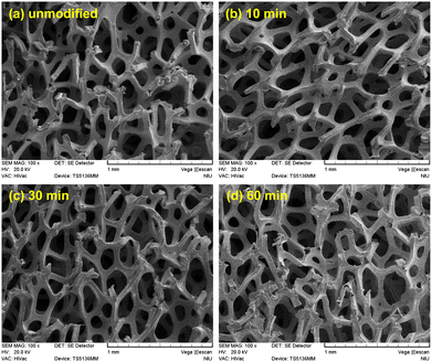 | ||
| Fig. 1 SEM images (100×) of the (a) unmodified and (b) 10, (c) 30, and (d) 60 min N2 plasma-modified Ni foam electrodes. | ||
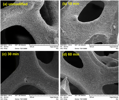 | ||
| Fig. 2 SEM images (1500×) of the (a) unmodified and (b) 10, (c) 30, and (d) 60 min N2 plasma-modified Ni foam electrodes. | ||
Wettability of Ni foam electrodes
Fig. 3 shows the water contact angle measurements for the unmodified and N2 plasma-modified Ni foam electrodes. As shown in Fig. 3, the unmodified Ni foam electrode exhibited a high water-contact angle of (98.0 ± 1.7)°, indicating that the surface of the unmodified Ni foam electrode was naturally hydrophobic. In contrast, the water contact angle of the Ni foam electrode approached zero after various durations of N2 plasma modification. This suggests that the surface of the Ni foam electrode became highly hydrophilic after the N2 plasma modification. In addition, the high hydrophilicity of the N2 plasma-modified Ni foam electrodes was retained for more than seven days.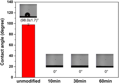 | ||
| Fig. 3 Water contact angle measurements of the unmodified and N2 plasma-modified Ni foam electrodes. | ||
XPS measurements of Ni foam electrodes
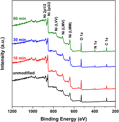
Fig. 4 shows the XPS survey spectra of the unmodified and N2 plasma-modified Ni foam electrodes. The XPS survey spectra of both the unmodified and N2 plasma-modified Ni foam electrodes exhibited characteristic peaks of nickel (approximately 854.2 and 871.7 eV for Ni 2p3/2 and Ni 2p1/2 peaks, respectively), a characteristic peak of oxygen (approximately 531.3 eV for the O 1s peak), and a relative lower characteristic peak of carbon (approximately 285.0 eV for the C 1s peak). The oxygen signal originated from native NiO oxide films formed on the surface, whereas the carbon signal originated from trace carbon contamination. In addition, the XPS spectra of the N2 plasma-modified Ni foam electrodes exhibited an additional characteristic nitrogen peak (approximately 398.0 eV for the N 1s peak), which was not observed in the spectra of the unmodified Ni foam electrode. This indicates that nitrogen species were introduced on the surface of the Ni foam electrodes after N2 plasma modification.Fig. 5(a)–(d) show the N 1s XPS spectra of the unmodified Ni foam electrode and those modified with 10, 30, an d 60 min of N2 plasma treatment, respectively. Fig. 5 shows that no obvious N 1s characteristic peak was observed on the surface of the unmodified Ni foam electrode, whereas the N2 plasma-modified Ni foam electrodes exhibited an N 1s characteristic peak. As shown in Fig. 5, the N 1s characteristic peak can be decomposed into major Ni–N and minor NH3 peaks at approximately 398.0 and 400.0 eV, respectively.31 In addition, the intensities of these characteristic peaks gradually increase with increasing plasma treatment duration. This indicates that more nitrogen species formed on the surface of the Ni foam with an increase in the plasma treatment time.
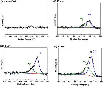 | ||
| Fig. 5 N 1s XPS spectra of the (a) unmodified and (b) 10, (c) 30, and (d) 60 min N2 plasma-modified Ni foam electrodes. | ||
Fig. 6(a)–(d) show the Ni 2p XPS spectra of the unmodified Ni foam electrode and those modified with 10, 30, and 60 min of N2 plasma treatment, respectively. Fig. 6(a) shows that the Ni 2p characteristic peaks of the unmodified Ni foam electrode can be divided into two oxidation states, metallic Ni and NiO, which correspond to 2p3/2 peaks at 854.2 and 856.3 eV, and 2p1/2 peaks at 871.7 and 873.6 eV, respectively. Except for the main metallic Ni and NiO characteristic peaks, Fig. 6(a) also shows that small shoulders were near the characteristic peaks. These small shoulders were the satellite (sat.) peaks corresponding to the metallic Ni (860.7 eV and 871.7 eV for Ni 2p3/2 sat. and Ni 2p1/2 sat., respectively) and NiO (862.2 eV and 880.3 eV for NiO 2p3/2 sat. and NiO 2p3/2 sat., respectively). Fig. 6(b)–(d) show that the Ni 2p XPS spectra of N2 plasma-modified Ni foam electrodes also exhibited substantial metallic Ni and NiO characteristic peaks. However, except of these metallic Ni and NiO characteristic peaks, an additional characteristic peak of Ni3N appeared at approximately 852.7 eV and 870.2 eV. This suggests that some Ni3N formed on the surface of N2 plasma-modified Ni foam electrodes. Besides, the relative intensities of the Ni3N characteristic peaks gradually increase with increasing plasma treatment time, indicating that more of Ni3N formed on the surface of Ni foam electrodes with the increase of plasma treatment interval.
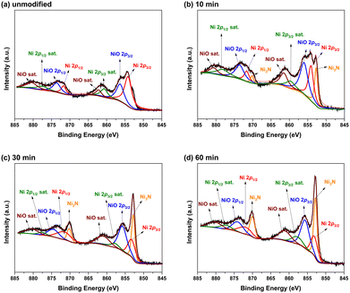 | ||
| Fig. 6 Ni 2p XPS spectra of the (a) unmodified and (b) 10, (c) 30, and (d) 60 min N2 plasma-modified Ni foam electrodes. | ||
Electrochemical performance of MFCs configured with Ni foam electrodes
Fig. 7(a) shows the power density response curves of the MFCs configured with unmodified Ni foam electrodes. The power density response curves of MFCs configured with graphite and Ni rod electrodes as anodes (both cathodes were Ni foam electrodes) are also presented for comparison. As shown in Fig. 7(a), the highest power density of the MFC configured with the unmodified Ni foam electrode was significantly higher than those of the MFCs configured with graphite or Ni rod electrodes. Fig. 7(b) shows a magnified image of the results presented in Fig. 7(a). According to Fig. 7, the highest power density of the MFCs configured with the unmodified Ni foam electrodes was approximately 166.9 mW m−2, whereas those of the MFCs configured with graphite and Ni rod electrodes were only approximately 29.5 and 5.1 mW m−2, respectively.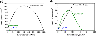 | ||
| Fig. 7 (a) Power density response curves of the MFCs configured with unmodified Ni foam, Ni rod, and graphite rod electrodes. (b) Magnified view of (a). | ||
Fig. 8(a) shows the power density response curves of the MFCs configured with the unmodified and N2 plasma-modified Ni foam electrodes. Fig. 8(a) reveals that the highest power densities of the MFC configured with the unmodified Ni foam electrode was 166.9 mW m−2 and those of the MFCs configured with modified Ni foam electrodes treated with N2 plasma for 10, 30, and 60 min were approximately 204.0, 222.8, and 247.1 mW m−2, respectively. This implies that the power-generating efficiencies of the MFCs can be effectively enhanced by N2 plasma modification. Fig. 8(b) shows the EIS results of the MFCs configured with the unmodified and N2 plasma-modified Ni foam electrodes. In Fig. 8(b), each MFC exhibits a single capacitive loop that can be fitted using a constant-phase-element (CPE) circuit model. The circuit comprised a CPE in parallel with a charge-transfer resistance (RCT), as shown in Fig. 8(b). The impedance of the CPE can be calculated as follows:  .32 The Z-View® software was adopted for fitting the impedance of the CPE; ϕ is denoted as CPE-P, and T is denoted as CPE-T. Table 1 lists the calculated values of RS, CPE-T, CPE-P, and RCT for the MFCs configured with the unmodified and N2 plasma-modified Ni foam electrodes. The RCT values correspond to the resistance to the electron transfer from bacteria to the electrode.33 The RCT value of the MFC configured with the unmodified Ni foam electrode was 302 Ω and those of the MFCs configured with modified Ni foam electrodes treated with N2 plasma for 10, 30, and 60 min were 226, 167, and 165 Ω, respectively.
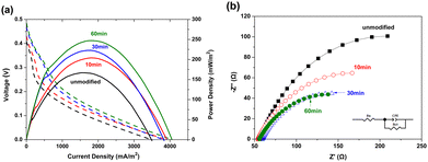 | ||
| Fig. 8 (a) Polarization and power density curves and (b) EIS results of the MFCs configured with unmodified and N2 plasma-modified Ni foam electrodes. | ||
| R S (Ω) | CPE-T | CPE-P | R CT (Ω) | |
|---|---|---|---|---|
| Unmodified | 56.80 | 0.0046 | 0.7449 | 302 |
| 10 min of N2 plasma | 53.79 | 0.0060 | 0.6614 | 226 |
| 30 min of N2 plasma | 59.05 | 0.0080 | 0.6269 | 167 |
| 60 min of N2 plasma | 55.47 | 0.0081 | 0.6201 | 165 |
Microbial colonization on Ni foam electrodes
Fig. 9(a)–(d) present the SEM images of the unmodified Ni foam electrode and modified Ni foam electrodes treated with N2 plasma for 10, 30, and 60 min, respectively, after soaking in the MFC chambers for 24 h. As shown in Fig. 9, some microorganisms and biofilm segments were observed on the surfaces of the N2 plasma-modified Ni foam electrodes, indicating that the N2 plasma treatment effectively facilitated the colonization of microorganisms on the hydrophilic surfaces of the Ni foam electrodes.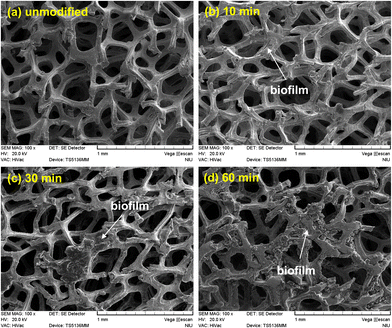 | ||
| Fig. 9 SEM images of the (a) unmodified and (b) 10, (c) 30, and (d) 60 min N2 plasma-modified Ni foam electrodes, after immersion in the chambers of the MFCs for 24 h. | ||
Discussion
Carbon-based materials are widely used as electrodes in MFCs because of their high chemical stability, low cost, and excellent biocompatibility. Nevertheless, the electrical conductivities of carbon-based materials are generally low, and this restricts the output of MFCs. In contrast, metallic materials possess much better electrical conductivities than typical carbon-based materials. In addition, electrochemically active bacteria are tolerant against the potentially toxic metal ions released from metallic electrodes.34,35 Therefore, metal electrodes are also suitable for use in MFCs. However, Schröder et al.21 showed that the electrochemical performance of MFCs configured with metal electrodes was not as good as expected. Similar results are shown in Fig. 7; the power-generating efficiency of the MFC configured with the Ni rod was only approximately one-sixth that of the MFC configured with a graphite rod. Schröder et al.21 indicated that this feature is due to the passive oxide layers on the surface of the Ni anode, which impede the charge-transfer between the microorganisms and anodes. However, as shown in Fig. 7, the power-generating efficiency of the MFC configured with the Ni foam electrode was approximately 30 times higher than that configured with the solid Ni rod electrode, even though the surface of the Ni foam was covered by a passive NiO layer, as demonstrated by the XPS results shown in Fig. 4 and 6. Accordingly, we suggest that the geometric structure of the anode is also critical for the electrochemical performance of MFCs. In this study, both Ni foam and graphite rod electrodes exhibited porous structures, providing large surface areas for bacterial adhesion. In addition, Ni foam electrodes had rough surface morphologies, which benefited the initial adhesion of bacteria for the development of biofilms.36,37 In contrast, the smooth and impenetrable surface of the solid Ni rod electrode was unfavorable for the adhesion and colonization of microorganisms, causing low electron transfer efficiency in MFCs. Although both the Ni foam and graphite rod electrodes exhibited an open-pore structure, the power-generating efficiency of the MFC configured with Ni foam was approximately five times higher than that of the MFC configured with a graphite rod. This is because the electrical resistivity of Ni (7.1 × 10⁻⁸ Ωm) is much lower than that of graphite (2.5 × 10⁻⁶ to 5.0 × 10⁻⁶ Ωm).21 Therefore, we suggest that metal foam electrodes, which exhibit porous structures with high surface areas, similar to traditional carbon-based materials currently used in MFCs, are also appropriate for application in MFCs.Although Ni foam is suitable for MFCs, its naturally hydrophobic surface must be further improved to facilitate bacterial adhesion in MFCs. Numerous techniques can be used to modify the surface characteristics of the electrodes used in MFCs.11–20 Among these, plasma modification is one of the superior candidates because it is clean, non-toxic, environmentally friendly, economical, and requires no exogenous chemical substances during the modification process.14,15 As shown in Fig. 8(a), the power density generated from the MFC configured with Ni foam electrode gradually increased from 166.9 to 247.1 mW m−2 with the extension of the N2 plasma treatment time from 0 to 60 min. In addition, the EIS results revealed that the RCT values of the MFCs configured with the N2 plasma-modified Ni foam electrodes decreased with increasing N2 plasma treatment time (Fig. 8(b) and Table 1). The RCT value, which corresponds to the resistance of the electrochemical reaction on the electrode,33 shows that N2 plasma modification effectively improves the charge transfer transport efficiencies of the Ni foam electrodes and thereby increases the power density of the MFCs. This is because the hydrophobic surface of the Ni foam electrode became highly hydrophilic after the N2 plasma treatment (Fig. 3), and the hydrophilicity of the N2 plasma-modified Ni foam electrodes favored bacterial colonization and biofilm formation (Fig. 9). The hydrophilicity of the surface of the N2 plasma-modified Ni foam electrode was due to the presence of sufficient hydrophilic Ni–N and NH3 functional groups on the surfaces of the Ni foam electrodes. In addition, the positive charge of the NH3 functional groups on the surface of Ni foam electrodes facilitated the formation of biofilms and adhesion of bacteria.11,38 In summary, Ni foam is suitable for use as an anode in MFCs because it combines the advantages of an open cellular structure and good electrical conductivity. The electrochemical performance of the MFCs configured with the Ni foam electrodes can be further improved by N2 plasma treatment because electrochemically active bacteria are more easily propagated onto a highly hydrophilic surface. However, the corrosion resistance of Ni-foam electrodes used in MFCs should be carefully considered and further enhanced for practical long-term service in the future.
Conclusions
In this study, we investigated the surface properties of N2 plasma-enhanced Ni foam electrodes and electrochemical performance of MFCs configured with these electrodes. The following conclusions were drawn.(1) MFCs configured with unmodified or N2 plasma-modified Ni foam anodes exhibit better electrochemical performance than those configured with dense solid Ni or graphite rods because Ni foam electrodes combine the advantages of high surface area structures and good electrical conductivity.
(2) N2 plasma modification introduces Ni–N and NH3 functional groups onto the surface of the Ni foam electrode. The amount of hydrophilic nitrogen species increases with the plasma treatment time.
(3) The N2 plasma modification does not influence the surface morphology of the Ni foam electrode. The surface of the Ni foam electrode becomes highly hydrophilic after the N2 plasma modification because of the introduced functional groups of the nitrogen species.
(4) MFCs configured with plasma-modified Ni foam anodes exhibit better power-generating efficiency than those configured with unmodified Ni foam anodes because electrochemically active bacteria propagate more easily onto a highly hydrophilic surface.
Author contributions
Mozhgan Gholami-Kermanshahi: conceptualization, investigation, writing – original draft. Ming-Cheng Lee: methodology, data curation, investigation, writing – original draft. Günther Lange: investigation, supervision. Shih-Hang Chang: methodology, investigation, writing – review & editing, resources, supervision, project administration, funding acquisition.Conflicts of interest
There are no conflicts to declare.Acknowledgements
The authors gratefully acknowledge the financial support for this research provided by the National Science and Technology Council (NSTC), Taiwan, under Grant NSTC 112-2221-E-197-014-MY2.References
- B. Logan, B. Hamelers, R. Rozendal, U. Schröder, J. Keller, S. Freguia, P. Aelterman, W. Verstraete and K. Rabaey, Environ. Sci. Technol., 2006, 40, 5181–5192 CrossRef CAS PubMed.
- D. Pant, G. Van Bogaert, L. Diels and K. Vanbroekhoven, Bioresour. Technol., 2010, 101, 1533–1543 CrossRef CAS PubMed.
- P. Pandey, V. N. Shinde, R. L. Deopurkar, S. P. Kale, S. A. Patil and D. Pant, Appl. Energy, 2016, 168, 706–723 CrossRef CAS.
- L. Koók, T. Rózsenberszki, N. Nemestóthy, K. Bélafi-Bakó and P. Bakonyi, J. Cleaner Prod., 2016, 112, 4406–4412 CrossRef.
- D. Mamais, C. Noutsopoulos, A. Dimopoulou, A. Stasinakis and T. D. Lekkas, Water Sci. Technol., 2015, 71, 303–308 CrossRef CAS PubMed.
- A. J. Slate, K. A. Whitehead, D. A. C. Brownson and C. E. Banks, Renewable Sustainable Energy Rev., 2019, 101, 60–81 CrossRef CAS.
- X. Huang, C. Duan, W. Duan, F. Sun, H. Cui, S. Zhang and X. Chen, J. Cleaner Prod., 2021, 301, 126951 CrossRef.
- Y. Wang, B. Li, D. Cui, X. Xiang and W. Li, Biosens. Bioelectron., 2014, 51, 349–355 CrossRef CAS PubMed.
- X. Liu, W. Wu and Z. Gu, J. Power Sources, 2015, 277, 110–115 CrossRef CAS.
- J. Wei, P. Liang and X. Huang, Bioresour. Technol., 2011, 102, 9335–9344 CrossRef CAS PubMed.
- S. A. Cheng and B. E. Logan, Electrochem. Commun., 2007, 9, 492–496 CrossRef.
- Y. Feng, Q. Yang, X. Wang and B. E. Logan, J. Power Sources, 2010, 195, 1841–1844 CrossRef CAS.
- Y. Qiao, X. S. Wu and C. M. Li, J. Power Sources, 2014, 266, 226–231 CrossRef CAS.
- S. H. Chang, J. S. Liou, J. L. Liu, Y. F. Chiu, C. H. Xu, B. Y. Chen and J. Z. Chen, J. Power Sources, 2016, 336, 99–106 CrossRef CAS.
- S. H. Chang, B. Y. Huang, T. H. Wan, J. Z. Chen and B. Y. Chen, RSC Adv., 2017, 7, 56433–56439 RSC.
- B. Y. Chen, Y. T. Tsao and S. H. Chang, Coatings, 2018, 8, 468 CrossRef.
- S. H. Chang, Y. T. Tsao and K. W. Tung, Mater. Sci., 2021, 27, 361–366 CrossRef.
- A. A. Yaqoob, M. N. M. Ibrahim and S. Rodríguez-Couto, Biochem. Eng. J., 2020, 164, 107779 CrossRef CAS.
- J. Ma, J. Zhang, Y. Zhang, Q. Guo, T. Hu, H. Xiao, W. Lu and J. Jia, J. Power Sources, 2023, 556, 232486 CrossRef CAS.
- J. Li, L. Yuan, Z. Wu, T. Zhang, C. Wang, M. Li, D. Shan and B. Guo, Appl. Surf. Sci., 2023, 639, 158189 CrossRef CAS.
- A. Baudler, I. Schmidt, M. Langner, A. Greiner and U. Schröder, Energy Environ. Sci., 2015, 8, 2048–2055 RSC.
- B. Erable, N. Byrne, L. Etcheverry, W. Achouak and A. Bergel, Int. J. Hydrogen Energy, 2017, 42, 26059–26067 CrossRef CAS.
- M. Füeg, Z. Borjas, M. Estevez-Canales, A. Esteve-Núñez, I. Pobelov, P. Broekmann and A. Kuzume, Bioelectrochemistry, 2019, 12, 130–136 CrossRef PubMed.
- A. Iannaci, T. P. Sciarria, B. Mecheri, F. Adani, S. Licoccia and A. D'Epifanio, J. Alloys Compd., 2017, 693, 170–176 CrossRef CAS.
- T. Yamashita and H. Yokoyama, Biotechnol. Biofuels, 2018, 11, 39 CrossRef PubMed.
- P. A. Selembo, M. D. Merrill and B. E. Logan, J. Power Sources, 2009, 190, 271–278 CrossRef CAS.
- A. Banerjee, R. K. Calay and M. Mustafa, Energies, 2022, 15, 2283 CrossRef CAS.
- G. Palanisamy, H. Y. Jung, T. Sadhasivam, M. D. Kurkuri, S. C. Kim and S. H. Roh, J. Cleaner Prod., 2019, 221, 598–621 CrossRef CAS.
- L. P. Lefebvre, J. Banhart and D. C. Dunand, Adv. Eng. Mater., 2008, 10, 775–787 CrossRef CAS.
- W. C. Tan, L. H. Saw, H. S. Thiam, J. Xuan, Z. Cai and M. C. Yew, Renewable Sustainable Energy Rev., 2018, 96, 181–197 CrossRef.
- B. He, Y. Yuan, J. Wang, E. Pervaiz, X. Dong, Z. Shao and M. Yang, Electrocatalysis, 2018, 9, 452–458 CrossRef CAS.
- J. B. Jorcin, M. E. Orazem, N. Pébère and B. Tribollet, Electrochim. Acta, 2006, 51, 1473–1479 CrossRef CAS.
- Y. Qiao, C. M. Li, S. J. Bao and Q. L. Bao, J. Power Sources, 2007, 170, 790–794 CrossRef.
- S. Patil, F. Harnisch and U. Schröder, Chem. Phys. Chem., 2010, 11, 2834–2837 CrossRef CAS PubMed.
- F. Kargi and S. Eker, J. Chem. Technol. Biotechnol., 2007, 82, 658–662 CrossRef CAS.
- M. Alnnasouri, C. Lemaitre, C. Gentric, C. Dagot and M. N. Pons, Biochem. Eng. J., 2011, 57, 38–45 CrossRef CAS.
- Y. Ammar, D. Swailes, B. Bridgens and J. Chen, Surf. Coat. Technol., 2015, 284, 410–416 CrossRef CAS.
- X. Wang, S. A. Cheng, Y. J. Feng, M. D. Merrill, T. Saito and B. E. Logan, Environ. Sci. Technol., 2009, 43, 6870–6874 CrossRef CAS PubMed.
| This journal is © The Royal Society of Chemistry 2024 |

