 Open Access Article
Creative Commons Attribution 3.0 Unported Licence
Synthesis and magneto-dielectric properties of Ti-doped Ni0.5Zn0.5TixFe2−xO4 ferrite via a conventional sol–gel process
M.
Farzana Alam
a,
M.
Atikur Rahman
 b,
Md. Sarowar
Hossain
 c,
M. N. I.
Khan
 d,
R.
Rashid
d,
M.
Saiful Islam
e,
William
Ghann
d,
R.
Rashid
d,
M.
Saiful Islam
e,
William
Ghann
 f,
M. K.
Alam
*a and
Jamal
Uddin
 *f
*f
aDepartment of Physics, Bangladesh University of Engineering and Technology, Dhaka 1000, Bangladesh. E-mail: khurshedphy@buet.ac.bd
bDepartment of Electrical and Electronic Engineering, University of Chittagong, Chittagong 4331, Bangladesh
cDepartment of Physics, Faculty of Science and Technology (FST), American International University-Bangladesh, Dhaka 1229, Bangladesh
dMaterial Science division, Atomic Energy Centre, Dhaka 1000, Bangladesh
eDepartment of Nanomaterials and Ceramic Engineering, Bangladesh University of Engineering and Technology, Dhaka 1000, Bangladesh
fCenter for Nanotechnology, Department of Natural Sciences, Coppin State University, Baltimore, MD, USA. E-mail: juddin@coppin.edu
First published on 30th October 2024
Abstract
Ni–Zn-based ferrites (NZFO) need to possess the ideal ratio of dielectric and magnetic characteristics for uses involving electromagnetic fields. Consequently, the NZFO system has been modified by Ti4+ substitution at Fe3+ producing Ni0.5Zn0.5TixFe2−xO4 (x = 0.00, 0.02, 0.04, 0.06, 0.08 and 0.10) and a conventional sol–gel process was followed for the synthesis. The structure of the synthesized samples was evaluated from the X-ray diffraction (XRD) patterns. Fourier transform infrared (FTIR) measurement provided information on chemical interaction with thermodynamic conditions. In addition, the grain sizes were obtained from scanning electron microscopy (SEM). Furthermore, the studied samples exhibit a notable light absorption in the visible spectrum with band gaps between 3.8 and 4.8 eV. The magneto-dielectric properties were analyzed by field (H) dependent magnetization (M), frequency-dependent permeability (μ), and permittivity (ε) measurements. Ti4+ substitution in NZFO led to a decrease in magnetic saturation (Ms) and μ while the values of creased and improved the mismatching impedance (Z/η0 = (μ′/ε′)1/2). The lowest value of Ms (14 emu g−1) is achieved for the sample with x = 0.1 for which μ is also the lowest. Finally, a stable value of Z/η0 (∼4.0) has been obtained for the x = 0.10 sample over a wide range of frequencies (1–10 MHz), making it suitable as a miniaturizing device material in this frequency range.
1. Introduction
Ferrites, a class of materials boasting a unique combination of magnetic, electrical, and thermal properties, have revolutionized numerous technological fields.1 Among these, Zn2+ incorporated ferrite system has potential applications as a multilayer chip inductor, transformer, in hyperthermia treatment, as a magneto-dielectric device, etc.2 Furthermore, soft magnetic spinel ferrites, particularly Ni–Zn-based ferrites (NZFO), have garnered significant attention due to their exceptional properties, such as high resistivity (106 Ω cm), low eddy current loss, elevated permeability, substantial saturation magnetization, and high Curie temperature.3–5 Due to these outstanding properties, these materials are well suited for several applications such as transformers, computer circuitry, high-frequency miniaturized antennas, and catalyst technology.6–10 In addition, the magnetic and electrical attributes of NZFO ensure remarkable electromagnetic properties11 and make them suitable for high-frequency applications within the radio frequency (RF) spectrum.12NZFO is a spinel ferrite having unit cells of face-centered cubic (FCC) structure from the Fd![[3 with combining macron]](https://www.rsc.org/images/entities/char_0033_0304.gif) m space group.13 Moreover, the chemical formula of NZFO is Ni1−xZnxFe2O4 following the general formula of spinel ferrite of (M2+)[Fe23+]O42−.13 The cation distribution in spinel ferrites is described as (A1−δBδ)[AδB2−δ]O4, where A corresponds to divalent metal ions and B corresponds to trivalent Fe3+ ions, (A1−δBδ) and [AδB2−δ], respectively.14 The magnetic ions (Ni, Fe) are distributed between the tetrahedral (A-site, 8a) and octahedral (B-site, 16d) sites of this spinel structure.15 The resultant magnetic moment of the spinel ferrite is related to the magnetic moments of A site (MA) and B site (MB) and can be represented as: nB = MB − MA.16 The diamagnetic Zn2+ ions prefer to sit at the tetrahedral site and typically reduce the magnetic moment of the A-sublattice thereby enhancing the resultant magnetization of the sample.16 Therefore, particle size and the cationic distributions between these two interstitial sites of spinel lattice play a key role in the magnetic and transport properties of Ni–Zn ferrites.17 In addition, the electrical conduction in NZFO is attributed to the existence of two oxidation states of Fe3+ (Fe3+/Fe2+) in both A and B sites.18 Therefore, the enhanced electric, magnetic, and magneto-dielectric properties of NZFO are governed by the cationic distribution in the spinel structure. These structural configurations are controlled by various factors such as methods of synthesis, heat treatment, and/or doping into the A-site or B-site.19 Consequently, numerous researchers have focused on exploring the capabilities of NZFO ferrites by the substitution of Fe3+ with various trivalent cations (Bi3+, Ag2+, Ho3+, Nd3+, Gd3+) leading to improved dielectric and magnetic properties as well as enhanced resistive characteristics.20–24 This substitution not only enhances the electromagnetic performance of the ferrite but also broadens its range of applications. In general Ni–Zn nanoferrites are soft ferrites with excellent magnetic, electrical and optical properties. In recent years, several studies were performed to tune the physical properties of Ni–Zn ferrite through transitional atom doping such as Ni0.4Zn0.6−xMnxFe2O4,25 Ni0.6−xZn0.4CoxFe2O4,26 Ni0.65Zn0.35CuxFe2−xO4,27 Ni0.5Zn0.5SmxFe2−xO4,28 Ni0.2Zn0.8CexFe2−xO4,29 Ni0.5Zn0.5CrxFe2−xO4,30etc. However, the inherent limitations of reasonable magneto-dielectric properties and stable permeability with enhanced band gaps restrict the applications of NZFO as antenna rods,31 miniaturizing device materials, high-frequency inductors, microwave absorbers, etc. Kadam reported that Ce3+ substitution at Fe3+ of octahedral sites reduces the saturation magnetization and the coercivity (Hc) is increased from ∼278 Oe to ∼918 Oe for 5.5% Fe3+ replacement.32 Since magnetic hardness is enhanced due to Ce3+ doping in the spinel structure it may reduce the efficiency for magneto-dielectric application. Ghodake et al. reported that the permeability (μ) of NZFO decreases with the substitution of Ti4+ at Fe3+ which is attributed to domain wall motion.33 However, the interplay between the structure, magnetization, and electrical properties of Ti4+-doped NZFO is crucial for optimizing the performance in targeted applications.
m space group.13 Moreover, the chemical formula of NZFO is Ni1−xZnxFe2O4 following the general formula of spinel ferrite of (M2+)[Fe23+]O42−.13 The cation distribution in spinel ferrites is described as (A1−δBδ)[AδB2−δ]O4, where A corresponds to divalent metal ions and B corresponds to trivalent Fe3+ ions, (A1−δBδ) and [AδB2−δ], respectively.14 The magnetic ions (Ni, Fe) are distributed between the tetrahedral (A-site, 8a) and octahedral (B-site, 16d) sites of this spinel structure.15 The resultant magnetic moment of the spinel ferrite is related to the magnetic moments of A site (MA) and B site (MB) and can be represented as: nB = MB − MA.16 The diamagnetic Zn2+ ions prefer to sit at the tetrahedral site and typically reduce the magnetic moment of the A-sublattice thereby enhancing the resultant magnetization of the sample.16 Therefore, particle size and the cationic distributions between these two interstitial sites of spinel lattice play a key role in the magnetic and transport properties of Ni–Zn ferrites.17 In addition, the electrical conduction in NZFO is attributed to the existence of two oxidation states of Fe3+ (Fe3+/Fe2+) in both A and B sites.18 Therefore, the enhanced electric, magnetic, and magneto-dielectric properties of NZFO are governed by the cationic distribution in the spinel structure. These structural configurations are controlled by various factors such as methods of synthesis, heat treatment, and/or doping into the A-site or B-site.19 Consequently, numerous researchers have focused on exploring the capabilities of NZFO ferrites by the substitution of Fe3+ with various trivalent cations (Bi3+, Ag2+, Ho3+, Nd3+, Gd3+) leading to improved dielectric and magnetic properties as well as enhanced resistive characteristics.20–24 This substitution not only enhances the electromagnetic performance of the ferrite but also broadens its range of applications. In general Ni–Zn nanoferrites are soft ferrites with excellent magnetic, electrical and optical properties. In recent years, several studies were performed to tune the physical properties of Ni–Zn ferrite through transitional atom doping such as Ni0.4Zn0.6−xMnxFe2O4,25 Ni0.6−xZn0.4CoxFe2O4,26 Ni0.65Zn0.35CuxFe2−xO4,27 Ni0.5Zn0.5SmxFe2−xO4,28 Ni0.2Zn0.8CexFe2−xO4,29 Ni0.5Zn0.5CrxFe2−xO4,30etc. However, the inherent limitations of reasonable magneto-dielectric properties and stable permeability with enhanced band gaps restrict the applications of NZFO as antenna rods,31 miniaturizing device materials, high-frequency inductors, microwave absorbers, etc. Kadam reported that Ce3+ substitution at Fe3+ of octahedral sites reduces the saturation magnetization and the coercivity (Hc) is increased from ∼278 Oe to ∼918 Oe for 5.5% Fe3+ replacement.32 Since magnetic hardness is enhanced due to Ce3+ doping in the spinel structure it may reduce the efficiency for magneto-dielectric application. Ghodake et al. reported that the permeability (μ) of NZFO decreases with the substitution of Ti4+ at Fe3+ which is attributed to domain wall motion.33 However, the interplay between the structure, magnetization, and electrical properties of Ti4+-doped NZFO is crucial for optimizing the performance in targeted applications.
Apart from this, NZFO for miniaturizing device applications is a function of the transmission wavelength (λ) through the material and can be expressed by the following formula34:
 | (1) |
 | (2) |
Therefore, magnetic materials must have low magnetic and dielectric loss tangent (tan![[thin space (1/6-em)]](https://www.rsc.org/images/entities/char_2009.gif) δ) values to perform with high efficiency in device applications. However, it is difficult to synthesize a desired material with a higher cutoff frequency for electromagnetic application at specific frequency bands and permeability (μ′) and permittivity (ε′) of appropriate proportions.
δ) values to perform with high efficiency in device applications. However, it is difficult to synthesize a desired material with a higher cutoff frequency for electromagnetic application at specific frequency bands and permeability (μ′) and permittivity (ε′) of appropriate proportions.
In this work, the NZFO system has been modified by the replacement of Ti4+ at Fe3+, preparing the composition of Ni0.5Zn0.5TixFe2−xO4 (x = 0.00, 0.02, 0.04, 0.06, 0.08, and 0.10). The goal of this work is to achieve reasonable magneto-dielectric properties. The impact of the altered microstructure on the samples' magnetic and dielectric characteristics was also investigated concurrently. As a result, the knowledge gained will clarify how Ti4+ doping affects NZFO system performance and open up new avenues for application design.36
2. Experimental procedures
2.1. Synthesis
Ti-substituted Ni–Zn ferrite nanoparticles have been prepared with the formula of Ni0.5Zn0.5TixFe2−xO4 (with x = 0.0, 0.02, 0.04, 0.06, 0.08, and 0.10). Raw materials of research-grade nitrates Ni(NO3)2·6H2O, Zn(NO3)2·6H2O, Fe(NO3)3·9H2O (India), and Ti(NO3)4 (Sigma Aldrich, Germany) have been used according to the stoichiometric ratio for the preparation of Ni–Zn–Ti ferrites by a conventional sol–gel process.37 Samples were dissolved in distilled water and uniformly mixed in a suitable amount of ethanol under continuous magnetic stirring of 300 rpm for 1 hour. After that, samples were placed on a hot plate with magnetic stirring at a constant temperature of 80 °C and the pH of the resulting solution was adjusted to 7 by slowly adding dilute ammonia (NH4) solution. The thus formed brownish viscous gel was placed in an electric oven for 24 h at 100 °C to dry. To find the phase formation temperature, the parent samples were sintered from 400 °C to 1200 °C for 4 h in a furnace. Finally, all doped samples of Ni0.5Zn0.5TixFe2−xO4 (with x = 0.0, 0.02, 0.04, 0.06, 0.08, and 0.10) were sintered at 1200 °C at which the maximum bulk density was observed.2.2. Characterization
Thermogravimetric analysis (TGA) and differential thermal analysis (DTA) were performed with a Pyris Series STA-8000. The temperature (T) range was 30 ≤ T ≤ 1000 with a rate of 20 °C min−1 under air ambient to determine the phase transition temperature. The chemical bonds in the calcined NPs were studied through Fourier transform infrared (FTIR) spectra obtained with a PerkinElmer 100 spectrometer. The crystalline phases and structural characteristics of powder samples were investigated by X-ray diffraction (XRD) (Thermo-Scientific ARL EQUINOX 1000) study with Cu-Kα (λ = 1.5406 Å) radiation. The surface morphology of the particles was studied using a field effect scanning electron microscope (FESEM) with a JSM-7610 FE-SEM analyzer. The samples were analyzed using a MacroRam Raman spectrometer to confirm if there is any phase transition. The optical band gap of the samples was measured using a UV-visible spectrophotometer (Shimadzu UV-2600). A Wayne Kerr impedance analyzer (6500B) was used to evaluate the dielectric behavior of the synthesized NPs. Before dielectric measurement, pellets of 6 mm in diameter and 1 mm in thickness were fabricated by compressing powders in a uniaxial press. For permeability measurement, toroid-shaped samples were prepared similarly. Finally, the magnetic properties were explored using a Quantum design dynacool physical property measurement system (PPMS) with variation of the magnetic field at room temperature (RT = 25 °C) ranging from 0 to ±2.0 T.3. Results and discussion
3.1. Thermal stability
The thermal stability of the synthesized parent sample with composition Ni0.5Zn0.5Fe2O4 (NZFO) has been confirmed from TGA and differential scanning calorimetry (DSC) conducted between 25 °C and 1000 °C. Fig. 1 presents the TGA and DSC curves for the calcined sample of Ni0.5Zn0.5Fe2O4 and a decomposition of the components is observed due to the thermally activated chemical reaction. In addition, Fig. 1(a) illustrates the TGA and DSC curves of Ni0.5Zn0.5Fe2O4 before heat treatment while Fig. 1(b) confirms the crystalline phase formation due to heat treatment at 400 °C for 24 hours. The decomposition follows several steps (Fig. 1(a)) with increasing temperature, and the first step of 3.5% of weight loss is observed between 25 °C and 120 °C which is attributed to the reduction of water molecules and –OH ions from the sample surface.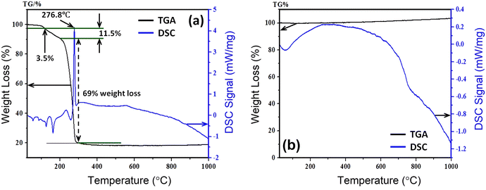 | ||
| Fig. 1 Thermal stability observation from TGA and DSC recorded (a) before heat treatment and (b) after heat treatment of Ni0.5Zn0.5Fe2O4 sample. | ||
Upon further heating from 120 °C to 210 °C, the evaporation of the remaining solvent and the crystallization process are ascribed to a considerable weight loss of 11.5% as a second step due to the decomposition of the surfactant. From 210 °C to 290 °C there is a sharp fall in weight (69%) with a sharp phase transition temperature at 276.8 °C. Beyond that the sample became stable up to 1000 °C which confirms the formation of pure-phase nickel–zinc spinel ferrite.38 The sample from the beginning to the ending of the experiment lost![[thin space (1/6-em)]](https://www.rsc.org/images/entities/char_2009.gif) ∼
∼![[thin space (1/6-em)]](https://www.rsc.org/images/entities/char_2009.gif) 20 wt%. Therefore, all the synthesized samples with the composition Ni0.5Zn0.5TixFe2−xO4 (with x = 0.0, 0.02, 0.04, 0.06, 0.08, and 0.10) were calcined at 400 °C for 4 h.
20 wt%. Therefore, all the synthesized samples with the composition Ni0.5Zn0.5TixFe2−xO4 (with x = 0.0, 0.02, 0.04, 0.06, 0.08, and 0.10) were calcined at 400 °C for 4 h.
3.2. FTIR analysis
FTIR analysis is a strong tool that can explain chemical interaction with thermodynamic condition and cationic bond formation in ferrites.23 Therefore, FTIR spectra were recorded at room temperature (RT = 25 °C) with the variation of wavenumber from 350 to 4000 cm−1, and a single spinel cubic structure is confirmed in all of the studied samples. Fig. 2 presents the FTIR spectra for the synthesized compositions of Ni0.5Zn0.5TixFe2−xO4 (x = 0.00, 0.02, 0.04, 0.06, 0.08 and 0.10). Here, two prominent absorption peaks are observed at 580 cm−1 and 360 cm−1 which are denoted as νA and νB respectively. Generally, the absorption band at 580 cm−1 is assigned for the motion of oxygen in the tetrahedral site (A-site) whereas the mode at 360 cm−1 corresponds to the octahedral site (B-site) for spinel ferrites.39,40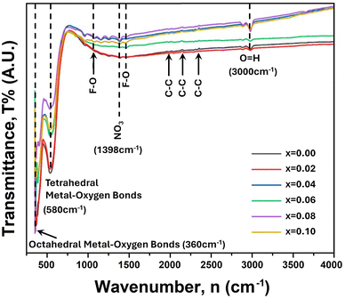 | ||
| Fig. 2 FTIR spectra for Ni0.5Zn0.5TixFe2−xO4 (where x = 0.00, 0.02, 0.04, 0.06, 0.08 and 0.10) scanned from 350 cm−1 to 4000 cm−1. | ||
In the studied sample the Fe3+–O2− and Ti4+–O2− bonds residing at the tetrahedral site (A) are associated with the vibrational frequency (νA) around 500 cm−1 to 600 cm−1 while the Fe3+–O2− and M2+–O2− (M = Fe, Zn, Ni) bonds correspond to the vibrational frequency (νB) around 450–350 cm−1. Several peaks of very weak vibration are observed at 2004, 2108, 2308 cm−1 which are attributed to the stretching of C–C.41 In addition, the absorption peaks at 1016 and 1511 cm−1 correspond to the molecular vibrations of Fe–O.42 The absorption peak intensity at 580 cm−1 (tetrahedral site) continues to decrease with increasing amount of Ti4+ and indicates the substitution of Fe3+ ions at this site. In addition, the ionic radius of Ti4+ (0.605 Å) is lower than that of Fe3+ (0.645 Å) for VI coordination number according to the database of ionic radii provided by Shannon.43 Therefore, Fe–O bonds at the tetrahedral site are highly affected when Ti4+ is substituted at Fe3+. Furthermore, the absence of any shoulder at 360 cm−1 confirms the presence of Fe2+ striking out of the octahedral site consequently. The slight shift of absorption bands at νA and νB to higher wavenumber indicates the perturbation in the Fe3+–O2− bond that occurred as a result of Ti4+ substitution.44
3.3. Structural analysis
The X-ray diffraction patterns for the synthesized compositions Ni0.5Zn0.5TixFe2−xO4 (x = 0.00, 0.02, 0.04, 0.06, 0.08 and 0.10) have been recorded at RT. The patterns are shown in Fig. 3, confirming the single-phase formation in all the samples, i.e. no impurity phase was detected. The peak pattern is similar to JCPDS #08-023445 which corresponds to the series of crystallographic planes (220), (311), (222), (400), (422), (333), (440), (620), (533), and (622). Therefore, a single spinel cubic structure of the Fd![[3 with combining macron]](https://www.rsc.org/images/entities/char_0033_0304.gif) m space group is confirmed in each synthesized sample. The structural parameters were calculated by the Rietveld refinement of XRD data employing Fullprof software.46,47 The fitting results are shown in Fig. 3 as red circles demonstrating the experimental data; black lines denoting the calculated intensities; and solid blue lines showing the difference between observed and calculated data. Furthermore, the green-colored vertical lines beneath each XRD pattern represent the Bragg positions. The extracted lattice parameters (a = b = c) along with crystallite size (ζ) and lattice strain (εL) are included in Table 1. In addition, the quality of fitting was expressed by reliability factors (R-factors) where Rp is the profile factor and Rwp is the weighted profile factor of the Rietveld refinement. The values of χ2 (goodness of fit) for the studied samples range from 1.6 to 3.1 (Table 1) which indicates a quality-based fitting.
m space group is confirmed in each synthesized sample. The structural parameters were calculated by the Rietveld refinement of XRD data employing Fullprof software.46,47 The fitting results are shown in Fig. 3 as red circles demonstrating the experimental data; black lines denoting the calculated intensities; and solid blue lines showing the difference between observed and calculated data. Furthermore, the green-colored vertical lines beneath each XRD pattern represent the Bragg positions. The extracted lattice parameters (a = b = c) along with crystallite size (ζ) and lattice strain (εL) are included in Table 1. In addition, the quality of fitting was expressed by reliability factors (R-factors) where Rp is the profile factor and Rwp is the weighted profile factor of the Rietveld refinement. The values of χ2 (goodness of fit) for the studied samples range from 1.6 to 3.1 (Table 1) which indicates a quality-based fitting.
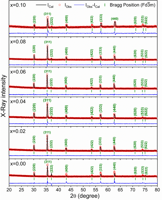 | ||
| Fig. 3 X-ray diffraction patterns with Rietveld refinement to evaluate the structural parameters for Ni0.5Zn0.5TixFe2−xO4 (x = 0.00, 0.02, 0.04, 0.06, 0.08 and 0.10). | ||
| Sample | a = b = c (Å) | V (Å3) | Fe–O bond length (Å) | ζ (×10−9 m) | ε L (×10−3) | δ (×1014 lines per m2) | Fitting parameters |
|---|---|---|---|---|---|---|---|
| x = 0.00 | 8.3970 (2) | 592.1 | 1.96 | 60.72 | 0.00196 | 2.71 | χ 2 = 1.6 |
| R p = 6.1, Rwp = 5.9 | |||||||
| x = 0.02 | 8.3903 (1) | 590.6 | 2.11 | 58.88 | 0.00202 | 2.88 | χ 2 = 2.3 |
| R p = 7.0, Rwp = 6.8 | |||||||
| x = 0.04 | 8.3816 (2) | 588.8 | 2.00 | 45.13 | 0.00263 | 4.91 | χ 2 = 2.6 |
| R p = 7.5, Rwp = 6.9 | |||||||
| x = 0.06 | 8.3788 (3) | 588.2 | 2.08 | 59.06 | 0.00201 | 2.87 | χ 2 = 2.2 |
| R p = 7.8, Rwp = 6.9 | |||||||
| x = 0.08 | 8.3734 (2) | 587.1 | 2.05 | 54.18 | 0.00219 | 3.41 | χ 2 = 2.8 |
| R p = 8.1, Rwp = 7.1 | |||||||
| x = 0.10 | 8.3596 (4) | 584.2 | 2.09 | 38.28 | 0.00309 | 6.82 | χ 2 = 3.1 |
| R p = 9.7, Rwp = 8.9 |
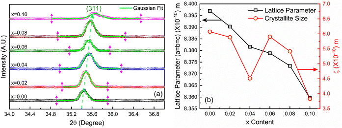
The obtained experimental value of the lattice constant (a = b = c) for all studied samples is near to the reported value for Ni–Co–Zn ferrites (8.3719 Å)48 and the slight variations occur due to the synthesis conditions and compositional effect. However, the major diffraction peak of (311) at 2θ ≈ 35.4° shifts to higher value as depicted in the magnified pattern of Fig. 4(a) and indicates the variation of the lattice parameters influenced by Ti doping. Here, Ti4+ with a lower ionic radius (0.605 Å) sits at the place of Fe3+ (0.645 Å). Therefore, the values of lattice parameters decrease with the increase of Ti4+ substitution at Fe3+ and the variations are illustrated in Fig. 4(b). In addition, the Fe–O bond length is also increased due to the substitution of Ti4+ at Fe3+ due to the presence of lattice strain (εL) within the crystal lattice.
Moreover, peak broadening is observed in the magnified XRD pattern of Fig. 4(a) which confirms the increase of εL in the Ti-doped NZFO and maximum broadening is observed for the sample of x = 0.10. For a close observation, the crystallite size (ζ) has been determined from the full width at half maximum (FWHM), β and the Bragg position (θ) as given by the Scherrer formula:49
 | (3) |
![[thin space (1/6-em)]](https://www.rsc.org/images/entities/char_2009.gif) tan
tan![[thin space (1/6-em)]](https://www.rsc.org/images/entities/char_2009.gif) θ.50 Therefore, the lattice strain (εL), i.e. micro-strain, was calculated using the following formula:
θ.50 Therefore, the lattice strain (εL), i.e. micro-strain, was calculated using the following formula: | (4) |
The values of crystallite size (ζ) and lattice strain (εL) have been included in Table 1. The maximum εL is observed for the sample with x = 0.10 that has the smallest crystallites.
3.4. Surface morphology and microstructural analysis
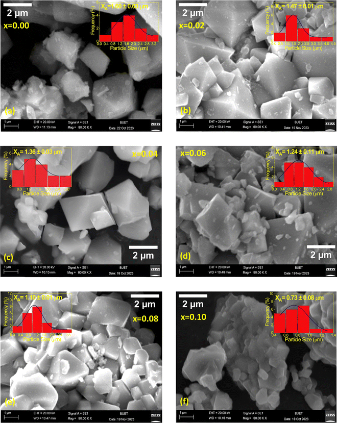
The microstructure of the synthesized compositions Ni0.5Zn0.5TixFe2−xO4 (x = 0.00, 0.02, 0.04, 0.06, 0.08 and 0.10) has been investigated using FESEM. Fig. 5 illustrates the morphology of the studied samples, and the grains are distinct in all micrographs. The grain sizes were obtained from the calibrating and line interpolation method using ImageJ 1.50i software. In this regard the sizes of several particles have been determined and the average size of the grains (XA) has been determined from the histogram of size distribution. The Gaussian fitting of particle size distribution shown in the insets of Fig. 5(a–f) was used to estimate the values of XA.It is observed that the grain sizes of the studied samples vary from 0.4 μm to 4.5 μm depending on the amount of Ti4+ substitution at Fe3+. However, though the ionic radius of Ti4+ (0.605 Å) is lower than that of Fe3+ (0.645 Å), the average grain sizes are gradually decreased due to doping. The lowest size, XA = 0.73 μm, is obtained for the sample with x = 0.10. Since the raw material Ti(NO3)4 has higher decomposition temperature (700) than Fe(NO3)3·9H2O material (20–400),51,52 the replacement of Ti4+ at Fe3+ works as a grain growth inhibitor resulting in a reduction of grain sizes. Therefore, the magnetic and electrical properties of the synthesized material are expected to result from the structural and microstructural evolution.53 The values of XA have been included in Table 2 and the results are concomitant with the crystallite size (ζ) obtained from the XRD data.
| Sample | X A (μm) | M s (emu g−1) | H c (Oe) | M r (emu g−1) | R (=Mr/Ms) |
|---|---|---|---|---|---|
| x = 0.00 | 1.60 ± 0.03 | 44 | 240 | 9.1 | 0.21 |
| x = 0.02 | 1.47 ± 0.01 | 32 | 170 | 5.3 | 0.17 |
| x = 0.04 | 1.36 ± 0.03 | 25 | 190 | 7.2 | 0.29 |
| x = 0.06 | 1.24 ± 0.11 | 26 | 150 | 3.1 | 0.12 |
| x = 0.08 | 1.10 ± 0.01 | 23 | 180 | 4.4 | 0.19 |
| x = 0.10 | 0.73 ± 0.08 | 14 | 175 | 2.6 | 0.19 |
3.5. Ultraviolet-visible (UV-vis) spectrometry
The UV-vis light absorption of the studied samples was measured with a diffuse reflectance instrument and Fig. 6 presents the results.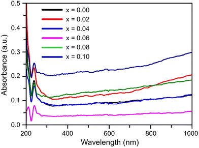 | ||
| Fig. 6 Ultraviolet-visible (UV-vis) absorption spectra measured for the composition of Ni0.5Zn0.5TixFe2−xO4 (x = 0.00, 0.02, 0.04, 0.06, 0.08 and 0.10) at room temperature (RT = 25 °C). | ||
It is observed that all the samples exhibit a strong absorption in the visible light range. The UV-vis spectrum shows a single primary absorption peak at about 270 nm, which is linked to n–π* transitions. This absorption is attributed to an electron transition from the valence band to the conduction band through an intrinsic band gap. The (αhυ)2versus photon energy plot for the studied samples is displayed in Fig. 7, which has been created by applying the Kubelka–Munk function54 to diffuse reflectance data. The graph illustrates how the absorption of Ti-doped Ni–Zn ferrite diminishes with increasing wavelength. The corresponding energy gap for all samples was calculated from Tauc's relation55αhυ = A(hυ − Eg)n where α is the absorption coefficient, hυ is the absorption energy, A is a constant that is independent of photon energy, Eg is the optical energy gap and n is a number with a value of 1/2 for direct band gap semiconductors.
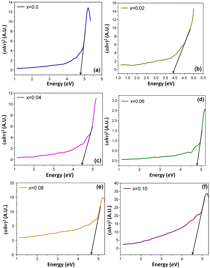 | ||
| Fig. 7 Tauc plots for optical band gap measurement for the composition of Ni0.5Zn0.5TixFe2−xO4, where (a) x = 0.00, (b) x = 0.02, (c) x = 0.04, (d) x = 0.06, (e) x = 0.08, and (f) x = 0.10. | ||
The linear extrapolation of (αhυ)2 on the energy axis is implemented to determine the optical band gap of the prepared samples, which is the difference in energy from the top of the valence band to the bottom of the conduction band.56 From the analysis, it is observed that the band gaps vary between 3.8 and 4.8 eV. Reduced grain size and introduction of Ti slightly altered the energy needed for electrons to jump, making the material absorb light differently. These shifts are likely due to imperfections and extra energy states created during sintering at 1200 °C temperature. The amount of oxygen vacancies inside the samples is also influenced by the annealing temperature. It produces trapped exciton states, which alter the absorption bands in the wavelength range around 600 nm by forming a sequence of metastable energy levels within the energy gap. Similar results were also reported by Jahan et al.57
3.6. Magnetic properties
The field-dependent magnetization (M–H) curves for Ni0.5Zn0.5TixFe2−xO4 (x = 0.00, 0.02, 0.04, 0.06, 0.08 and 0.10) are shown in Fig. 8 where the applied field (H) was varied up to ±20 kOe.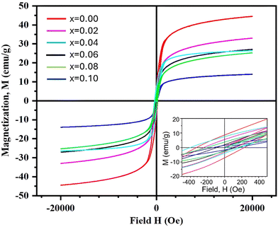 | ||
| Fig. 8 Magnetization M–H curves for the composition of Ni0.5Zn0.5TixFe2−xO4 (x = 0.00, 0.02, 0.04, 0.06, 0.08 and 0.10) measured at room temperature (RT = 25 °C). | ||
All the samples show a ferromagnetic nature at room temperature (RT = 25 °C). The coercivity (Hc) for all studied samples has been estimated from the equation Hc = |(Hc1 − Hc2)|/2, where Hc1 and Hc2 are the left and right coercive fields of the M–H loop at zero magnetization. The values of magnetic saturation (Ms), coercivity (Hc), remanent magnetization (Mr) and residual magnetization ratio (R) are included in Table 2. It is observed that the values of Ms decrease with an increase of the amount of Ti4+ at the site of Fe3+ in NZFO samples. These results are in agreement with the microstructure and particle size (Fig. 5) as the average grain size (XA) is lowest for the sample with x = 0.10 compared to the other studied samples.
Since a smaller particle size implies a larger surface-to-volume ratio, the compensation of magnetic moments at the surface of the x = 0.10 sample is much lower than that of the other samples. Therefore, the net magnetization decreases as the grain sizes are decreased due to substitution of Ti4+. Moreover, the magnetic moment of T4+ (1.73μB) is much lower than that of Fe3+ (5.59μB). Titanium ions (Ti4+) prefer to occupy specific sites (B sites) within the material's structure58 and B sites are normally occupied by iron ions (Fe3+).
3.7. Frequency-dependent permeability
The frequency-dependent magnetic properties of the studied samples have been analyzed from the measurement of permeability (μ) and it defines the degrees of magnetic response due to the applied magnetic field with frequency variation. Fig. 9 shows the frequency-dependent permeability, both the real part (μ′) and imaginary part (μ′′), for Ni0.5Zn0.5TixFe2−xO4 (x = 0.00, 0.02, 0.04, 0.06, 0.08 and 0.10) at room temperature (RT = 25 °C).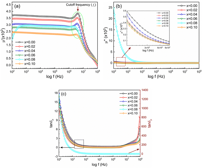 | ||
Fig. 9 Frequency-dependent magnetic properties represented by (a) real part of permeability (μ′), (b) imaginary part of permeability (μ′′) and (c) magnetic loss (tan![[thin space (1/6-em)]](https://www.rsc.org/images/entities/char_2009.gif) δμ). δμ). | ||
The initial magnetic permeability (μ′) is observed to vary in the samples with the variation of x from 0.0 to 1.0. The sample with x = 0.10 shows the lowest value of permeability (μ′). Generally, magnetic permeability originates due to spin rotation and domain wall motion which are embedded by structural deformation of grain sizes and intra-granular pores. Therefore, the initial part of real permeability is expressed as μ′ = 1 + χspin + χdw, where χspin = 2πMs2/K and χdw = 3πMs2XA/4γ denote the susceptibility due to spin rotation and domain wall motion respectively. Therefore, the distribution and decrease in average grain sizes XA weaken the domain wall mobilization, decreasing the value of μ′.59 According to the previous discussion, the grain size of NZFO is influenced by the addition of Ti4+ content which also contributes to an increase in magnetization. From Fig. 9(a) it is also seen that in the lower frequency region, μ′ is almost constant, but, with an increase in frequency, μ′ gradually decreases just after generating a characteristic peak corresponding to Snoek's law60 which states that μ′ ∝ 1/fc or μ′ × fc = constant, where fr is resonance or cut-off frequency (fc). So, the higher value of permeability has a low cut-off frequency and it is essential to keep low losses at that range of frequencies for application purposes. From Fig. 9(b) it is perceived that μ′′ decreases at a lower frequency, remaining constant up to 108 Hz. In addition, magnetic loss tangent (tan![[thin space (1/6-em)]](https://www.rsc.org/images/entities/char_2009.gif) δμ) is manifested by the lagging of domain wall motion and applied AC magnetic field.61 At higher frequency, tan
δμ) is manifested by the lagging of domain wall motion and applied AC magnetic field.61 At higher frequency, tan![[thin space (1/6-em)]](https://www.rsc.org/images/entities/char_2009.gif) δμ is initiated from natural ferromagnetic resonance.62 The rapid variation in the AC field at higher frequencies slows down the space charge activity which also accounts for magnetic losses.63
δμ is initiated from natural ferromagnetic resonance.62 The rapid variation in the AC field at higher frequencies slows down the space charge activity which also accounts for magnetic losses.63
3.8. Frequency-dependent electric polarization and relaxation
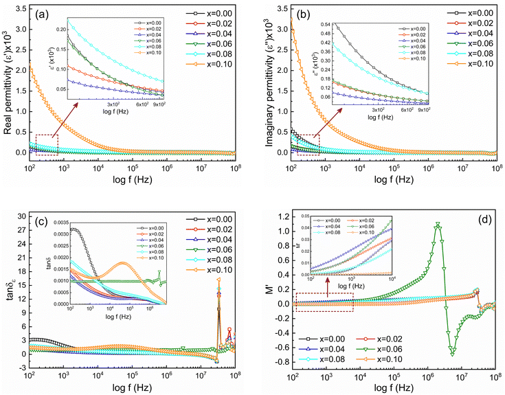
Frequency-dependent dielectric properties of Ni0.5Zn0.5TixFe2−xO4 (x = 0.00, 0.02, 0.04, 0.06, 0.08 and 0.10) samples have been investigated to estimate the electronic response and its relaxation phenomena in the studied samples. In general, materials with high permittivity (ε) polarize more in response to an applied electric field while materials with low dielectric constant (ε) can store more energy inside. Fig. 10(a) shows the frequency-dependent real part of the permittivity (ε′) and Fig. 10(b) shows the imaginary part (ε′′) for all studied samples. The measurement was performed at RT with a frequency range of 100 Hz to 100 MHz. At the beginning all the samples have high permittivity, both real (ε′) and imaginary (ε′′). Generally, a higher value of ε′ at lower frequency is attributed to the dipolar, space, or surface polarization, playing a leading role in determining the dielectric properties of dielectric materials.64 High values of ε′ are also an indication of the presence of charge defects originating from oxygen vacancies in samples.65 Therefore, the higher values of ε′ for x = 0.8 and x = 0.10 samples at lower frequencies are attributed to the space charge polarization caused by the non-uniform crystalline structure following the SEM observations. However, the dielectric dispersion is observed for all the samples above 1 kHz. According to Koop's phenomenological theory, this dispersion is caused by interfacial polarization.66 At low-frequency regions, the polarization is mainly attributed to electronic exchange between Fe2+ ↔ Fe3+ ions on the octahedral sites in the ferrite lattice.67 For Ni0.5Zn0.5TixFe2−xO4 composition the presence of Ni3+/Ni2+ ions in B sites yields p-type charge carriers whereas Fe3+/Fe2+ ions play a role of n-type charge carriers. As the p-type charge carriers are less mobile compared to the n-type charge carriers, the polarization arises due to p-type carriers showing a decreasing trend even at lower frequencies as compared to n-type carriers. Hence, the net polarization decreases, and a greater decrease is found with enhanced frequency and, consequently, permittivity decreases from 1 kHz to 100 MHz. Fig. 10(c) shows the frequency-dependent dielectric loss (tan![[thin space (1/6-em)]](https://www.rsc.org/images/entities/char_2009.gif) δε) that has been calculated from the ratio between imaginary and real parts of permittivity (tan
δε) that has been calculated from the ratio between imaginary and real parts of permittivity (tan![[thin space (1/6-em)]](https://www.rsc.org/images/entities/char_2009.gif) δε = ε′′/ε′) for the studied samples.
δε = ε′′/ε′) for the studied samples.
It is observed that tan![[thin space (1/6-em)]](https://www.rsc.org/images/entities/char_2009.gif) δε decreases as the frequency increases for all studied samples except for the sample with x = 0.06. The overall decrease in tan
δε decreases as the frequency increases for all studied samples except for the sample with x = 0.06. The overall decrease in tan![[thin space (1/6-em)]](https://www.rsc.org/images/entities/char_2009.gif) δε signifies the enhancement of the dielectric properties and the sample with x = 0.04 shows the lowest loss. However, the abnormal tan
δε signifies the enhancement of the dielectric properties and the sample with x = 0.04 shows the lowest loss. However, the abnormal tan![[thin space (1/6-em)]](https://www.rsc.org/images/entities/char_2009.gif) δε for the sample with x = 0.06 is attributed to the resonance effect.68 Apart this, the value for samples with x = 0.00 and 0.10 tends to increase at the beginning with a large relaxation peak which is observed in the magnified inset of Fig. 10(c). This nature is attributed to the existence of potential barriers with double ionized oxygen ion vacancies that provide hopping motion. Moreover, at higher frequencies (≥3 MHz) all samples present peaking behavior according to Debye relaxation theory. These loss peaks occur when the jumping frequency of electrons between Fe2+ and Fe3+ is equal to the frequency of applied field and the condition ωτ = 1 is satisfied, where ω = 2πf and τ is the relaxation time. When the hopping frequency of the charge carrier matches well with the frequency of the applied electric field, the maximum electrical energy is transferred to the oscillating ions and a peak is observed because of power loss. A similar kind of behavior is also observed in case of Al3+-substituted Ni–Zn ferrites.69
δε for the sample with x = 0.06 is attributed to the resonance effect.68 Apart this, the value for samples with x = 0.00 and 0.10 tends to increase at the beginning with a large relaxation peak which is observed in the magnified inset of Fig. 10(c). This nature is attributed to the existence of potential barriers with double ionized oxygen ion vacancies that provide hopping motion. Moreover, at higher frequencies (≥3 MHz) all samples present peaking behavior according to Debye relaxation theory. These loss peaks occur when the jumping frequency of electrons between Fe2+ and Fe3+ is equal to the frequency of applied field and the condition ωτ = 1 is satisfied, where ω = 2πf and τ is the relaxation time. When the hopping frequency of the charge carrier matches well with the frequency of the applied electric field, the maximum electrical energy is transferred to the oscillating ions and a peak is observed because of power loss. A similar kind of behavior is also observed in case of Al3+-substituted Ni–Zn ferrites.69
Furthermore, according to the Brick model approach of the dielectric response, the effective permittivity (ε) is connected with permittivity at the grain boundary (εgb) and grain interior (εi) and as given by the following formula:
 | (5) |
 | (6) |
 | (7) |
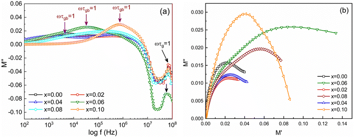
Fig. 10(d) shows frequency-dependent M′ for the studied samples measured from 100 Hz to 100 MHz. It is observed that at lower frequencies (inset of Fig. 10(d)) the values of M′ are lower and gradually increase with frequency in all samples. Fig. 11(a) shows the frequency-dependent imaginary part of the electric modulus (M′′). Of note, two distinct peaks of M′′ are observed for all studied samples depending on the frequency range. The first peak of M′′ at lower frequency (fR) corresponds to relaxation from grain boundaries (ωτgb = 1) while at higher frequency fR are the relaxation peak from grains (ωτg = 1). The relaxation time (τR) can be obtained from fR by using the relation τR = 1/2πfR. The values of relaxation time, τgb and τg for all studied samples are depicted in Table 3. In addition, the contribution of grains or grain boundaries in the relaxation process can be confirmed from the modulus plane plot (imaginary M′′ versus real M′) that is illustrated in Fig. 11(b).
![[thin space (1/6-em)]](https://www.rsc.org/images/entities/char_2009.gif) δε) and the relaxation time due to grain boundaries (τgb) and grains (τg) obtained for Ni0.5Zn0.5TixFe2−xO4 (x = 0.00, 0.02, 0.04, 0.06, 0.08 and 0.10) samples at 25 °C
δε) and the relaxation time due to grain boundaries (τgb) and grains (τg) obtained for Ni0.5Zn0.5TixFe2−xO4 (x = 0.00, 0.02, 0.04, 0.06, 0.08 and 0.10) samples at 25 °C
| Sample | ε′ | ε′′ | tan![[thin space (1/6-em)]](https://www.rsc.org/images/entities/char_2009.gif) δε δε |
τ g(s) (×10−5) | τ g (s) (×10−9) | |||
|---|---|---|---|---|---|---|---|---|
| 0.1 kHz | 100 kHz | 0.1 kHz | 100 kHz | 0.1 kHz | 100 kHz | |||
| x = 0.00 | 184.9 | 19.1 | 577.4 | 5.1 | 3.1 | 0.3 | 3.41 | 2.21 |
| x = 0.02 | 109.4 | 19.8 | 161.2 | 4.9 | 1.5 | 0.2 | 6.12 | 2.22 |
| x = 0.04 | 73.7 | 17.6 | 90.6 | 4.1 | 1.2 | 0.2 | 12.40 | 2.34 |
| x = 0.06 | 172.4 | 3.2 | 172.4 | 3.2 | 1.0 | 1.0 | 0.45 | 2.81 |
| x = 0.08 | 223.2 | 18.1 | 413.7 | 7.3 | 1.8 | 0.4 | 0.08 | 2.22 |
| x = 0.10 | 2148.7 | 32.1 | 3241.4 | 51.6 | 1.5 | 1.6 | 0.02 | 2.23 |
Here the smaller semicircle arcs are observed for 0 ≤ x ≤ 0.04 which corresponds to weak grain boundary effects rather than dominant grain effects70 while arcs become larger for higher Ti4+ substitution (0.06 ≤ x ≤ 0.10).
3.9. Magneto-dielectric properties
The matching magneto-dielectric properties of all the studied samples are obtained from Fig. 9(a) and 10(a). The transmission wavelength (λ) was measured from the permeability (μ′) and permittivity (ε′) using eqn (1). The mismatching in the impedance of antenna substrates (Z) and air (η0) disturbs the reflected energy during the radiation of the electromagnetic waves from the antenna where Z and η0 ratio can be determined from the relation as in eqn (2). In Fig. 12 the ratio of Z/η0 and frequency-dependent transmission wavelength (λ) are shown for the frequency range from 100 Hz to 10 MHz. The sample with x = 0.10 has a stable Z/η0 (∼4) over a wide frequency range (1–10 MHz) while the other samples show higher and unstable matching values that gradually fall to a lower value as the frequency increases. This result is attributed to the decrease in magnetic saturation (Ms) and permeability (μ′) along with an increase in the dielectric constant (ε′) achieved for the increase Ti4+ ions at the site of Fe3+ in the studied NZFO system. Hence, it is expected that the composition for x = 0.10 could be excellent for the application as a miniaturizing device over the frequency range of 1 MHz to 10 MHz. From Fig. 12(b) it is also confirmed that the transmission wavelength (λ) reaches a minimum in this frequency range.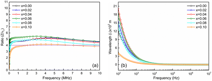 | ||
| Fig. 12 (a) Ratio of Z and η0 and (b) frequency-dependent transmission wavelength (λ) for Ni0.5Zn0.5TixFe2−xO4 (x = 0.00, 0.02, 0.04, 0.06, 0.08 and 0.10) samples at room temperature (RT = 25 °C). | ||
4. Conclusions
This study confirms the growth of the highly crystalline cubic spinel structure of Fd![[3 with combining macron]](https://www.rsc.org/images/entities/char_0033_0304.gif) m space group in the synthesized composition of Ni0.5Zn0.5TixFe2−xO4 (x = 0.00, 0.02, 0.04, 0.06, 0.08 and 0.10) using the conventional sol–gel method. The average grain sizes are decreased due to the substitution of Ti4+ at Fe3+ of NZFO samples, and the smallest grains (∼0.73 μm) are observed in the composition of Ni0.5Zn0.5Ti0.1Fe1.9O4. However, no remarkable variations in the optical band gap (Eg) are observed due to Ti4+ substitution in the studied samples. The values of Eg are varied between 3.8 eV and 4.8 eV which signifies the imperfections and extra energy states created during high-temperature processing. Furthermore, increased Ti4+ substitution in the NZFO system results in decreased magnetic saturation (Ms) and permeability (μ), and increased cutoff frequency (fc). Parallelly, the dielectric constants (ε′ and ε′′) are increased for greater Ti4+ substitution. Finally, the mismatching impedance (Z/η0), i.e. ratio between μ and ε, is decreased when replacing Fe3+ by Ti4+. The lowest and most stable value of Z/η0 (≈4.0) is obtained for the x = 0.1 sample over a wide range of frequencies (1–10 MHz). Therefore, Ni0.5Zn0.5Ti0.1Fe1.9O4 could be an excellent material for assembling miniaturizing devices exploited in the range between 1 MHz and 10 MHz. It is expected that greater Ti4+ (x > 0.10) substitution will result in more suitable and stable values of Z/η0 (≈1).
m space group in the synthesized composition of Ni0.5Zn0.5TixFe2−xO4 (x = 0.00, 0.02, 0.04, 0.06, 0.08 and 0.10) using the conventional sol–gel method. The average grain sizes are decreased due to the substitution of Ti4+ at Fe3+ of NZFO samples, and the smallest grains (∼0.73 μm) are observed in the composition of Ni0.5Zn0.5Ti0.1Fe1.9O4. However, no remarkable variations in the optical band gap (Eg) are observed due to Ti4+ substitution in the studied samples. The values of Eg are varied between 3.8 eV and 4.8 eV which signifies the imperfections and extra energy states created during high-temperature processing. Furthermore, increased Ti4+ substitution in the NZFO system results in decreased magnetic saturation (Ms) and permeability (μ), and increased cutoff frequency (fc). Parallelly, the dielectric constants (ε′ and ε′′) are increased for greater Ti4+ substitution. Finally, the mismatching impedance (Z/η0), i.e. ratio between μ and ε, is decreased when replacing Fe3+ by Ti4+. The lowest and most stable value of Z/η0 (≈4.0) is obtained for the x = 0.1 sample over a wide range of frequencies (1–10 MHz). Therefore, Ni0.5Zn0.5Ti0.1Fe1.9O4 could be an excellent material for assembling miniaturizing devices exploited in the range between 1 MHz and 10 MHz. It is expected that greater Ti4+ (x > 0.10) substitution will result in more suitable and stable values of Z/η0 (≈1).
Author contribution
Authors MFA, MAR and MKA and MSH contributed to the concept design and material preparation and preparation of the first draft. Data collection were done by MNIK, RR and MSI and data collections. Analysis were performed by MSH, WG and JU. All authors contributed to the review version manuscript and have approved the final manuscript.Data availability
Data in this paper are available upon request.Conflicts of interest
There are no conflicts to declare.Acknowledgements
The authors are expressing their acknowledgement to the Committee for Advanced Studies and Research (CASR), Bangladesh University of Engineering and Technology (BUET), Dhaka-1000, Bangladesh, for providing full financial support. We also expressing gratitude and thanks to the Materials Science Division, Atomic Energy Center, Shahbag, Dhaka 1000, Bangladesh, Department of Nanomaterials and Ceramic Engineering (NCE), BUET, for providing lab facilities.References
- J. D. Adam, L. E. Davis, G. F. Dionne, E. F. Schloemann and S. N. Stitzer, IEEE Trans. Microwave Theory Tech., 2002, 50(3), 721–737, DOI:10.1109/22.989957.
- R. S. Shitole, V. K. Barote, S. B. Kadam, S. S. Kadam, S. R. Wadgane, V. S. Shinde, S. Hussain, K. M. Batoo, S. E. Shirsath and R. H. Kadam, J. Magn. Magn. Mater., 2023, 588(B), 171468, DOI:10.1016/j.jmmm.2023.171468.
- A. M. Abdeen, J. Magn. Magn. Mater., 1998, 185, 199–206 CrossRef CAS.
- M. Jalaly, M. H. Enayati, P. Kameli and F. Karimzadeh, Phys. B, 2010, 405, 507–512 Search PubMed.
- A. K. M. Akther Hossain, M. Seki, T. Kawai and H. Tabata, J. App. Phys., 2004, 96, 1273 CrossRef CAS.
- Z. Shaterabadi, G. Nabiyouni and M. Soleymani, Prog. Biophys. Mol. Biol., 2018, 133, 9–19 Search PubMed.
- K. M. Batoo and M. S. Ansari, Nanoscale Res. Lett., 2012, 7, 112 CrossRef PubMed.
- J. A. Paulsen, A. P. Ring, C. C. H. Lo, J. E. Snyder and D. C. Jiles, J. Appl. Phys., 2005, 97, 044502 CrossRef.
- M. Hashim, et al. , J. Magn. Magn. Mater., 2015, 381, 416–421 CrossRef CAS.
- M. A. Busharat, S. Shukrullah, M. Y. Naz, Y. Khan, A. A. Ibrahim and A. Ali Al-Arainy, ACS Omega, 2024, 9(13), 14791–14804, DOI:10.1021/acsomega.3c06883.
- A. V. Knyazev, I. Zakharchuk, E. Lähderanta, K. V. Baidakov, S. S. Knyazeva and I. V. Ladenkov, J. Magn. Magn. Mater., 2017, 435, 9–14 CrossRef CAS.
- P. Thakur, S. Taneja, D. Chahar, B. Ravelo and A. Thakur, J. Magn. Magn. Mater., 2021, 530, 167925 CrossRef CAS.
- D. V. Phugate, R. B. Borade and S. B. Kadam, et al. , J. Supercond. Nov. Magn., 2020, 33, 3545–3554, DOI:10.1007/s10948-020-05616-w.
- D. R. Mane, D. D. Birajdar, S. Patil, S. E. Shirsath and R. H. Kadam, J. Sol-Gel Sci. Technol., 2011, 58, 70–79 Search PubMed.
- P. G. Bercoff and H. R. Bertorello, J. Magn. Magn. Mater., 2000, 213, 56–62 CrossRef CAS.
- R. Shitole, V. K. Barote and M. L. Mane, et al. , J. Mater. Sci.: Mater. Electron., 2023, 34, 1106, DOI:10.1007/s10854-023-10531-6.
- B. D. Cullity, Introduction to Magnetic Materials, Addison-Wesley, New York, 1972 Search PubMed.
- J. Smith and H. P. J. Wijn, Ferrites, John-Wiley, New york, 1959 Search PubMed.
- D. A. Vinnik, et al. , Ceram. Int., 2022, 48, 18124–18133 Search PubMed.
- K. L. Routray and D. Behera, J. Mater. Sci.: Mater. Electron., 2018, 29, 14248–14260 Search PubMed.
- K. L. Routray, S. Saha, D. Sanyal and D. Behera, Mater. Res. Express., 2018, 6, 026107 CrossRef.
- Krutika L. Routray and Sunirmal Saha, Phys. Scr., 2024, 99, 055950, DOI:10.1088/1402-4896/ad3ae0.
- K. L. Routray, S. Saha and D. Behera, Phys. Status Solidi B, 2019, 256, 1800676 Search PubMed.
- K. L. Routray, D. Sanyal and D. Behera, J. Appl. Phys., 2017, 122, 224104 Search PubMed.
- S. Ramesh, B. Dhanalakshmi and B. Chandra Sekhar, et al. , Appl. Phys. A: Mater. Sci. Process., 2016, 122, 1–8 CrossRef CAS.
- R. Kumar, H. Kumar, R. R. Singh and P. B. Barman, J. Sol-Gel Sci. Technol., 2016, 78, 566–575 Search PubMed.
- C. S. Kim, W. C. Kim, S. Y. An and S. W. Lee, J. Magn. Magn. Mater., 2000, 215, 213–216 Search PubMed.
- Z. Liu, Z. Peng, C. Lv and X. Fu, Ceram. Int., 2017, 43, 1449–1454 Search PubMed.
- D. Ravinder and A. Edukondalu, Chin. J. Phys., 2023, 81, 171–180 Search PubMed.
- S. Nasir, M. Anis-ur-Rehman and M. A. Malik, Phys. Scr., 2011, 83, 25602 Search PubMed.
- M. D. Hossain, A. T. M. K. Jamil, Md Sarowar Hossain, S. J. Ahmed, H. N. Das, R. Rashid, M. A. Hakim and M. N. I. Khan, RSC Adv., 2022, 12, 4656–4671 Search PubMed.
- S. S. Kadam, V. D. More and P. K. Gaikwad, et al. , Appl. Phys. A: Mater. Sci. Process., 2023, 129, 730, DOI:10.1007/s00339-023-07021-1.
- J. S. Ghodake and P. K. Maskar, Int. J. Mater. Sci., 2017, 12(1), 153–160 Search PubMed.
- Y. Peng, X. Wua, Z. Chen, W. Liu, F. Wang, X. Wang, Z. Feng, Y. Chen and V. G. Harris, J. Alloys Compd., 2015, 630, 48–53 Search PubMed.
- T. Krishnaveni, S. R. Murthy, F. Gao, Q. Lu and S. Komarneni, J. Mater. Sci., 2006, 41(5), 1471–1474 Search PubMed.
- Q. Li, Y. Chen, C. Yu, L. Young, J. Spector and V. G. Harris, Acta Mater., 2022, 231, 117854, DOI:10.1016/j.actamat.2022.117854.
- S. Sakka, J. Sol-Gel Sci. Technol., 2022, 102, 478–481 Search PubMed.
- A. Astafyev, E. Lysenko, A. Surzhikov, E. Nikolaev and V. Vlasov, J. Therm. Anal. Calorim., 2020, 142, 1775–1781 CrossRef CAS.
- K. Mohit, V. R. Gupta and S. K. Rout, Prog. Electromag. Res., 2014, B 57, 157–175 CrossRef.
- R. H. Kadam, R. Shitole, S. B. Kadam, K. Desai, A. P. Birajdar and V. K. Barote, et al. , Nanomaterials, 2023, 13, 1165, DOI:10.3390/nano13071165.
- A. T. Al-Douri, A. S. Ibraheam, R. Gdoura, Y. Al-Douri and A. F. Abd El-Rehim, J. Taibah Univ. Sci., 2021, 15(1), 275–281, DOI:10.1080/16583655.2021.1978834.
- S. P. Patil, S. K. Shinde and V. M. Desai, et al. , Res. Chem. Intermed., 2023, 49, 3481–3500, DOI:10.1007/s11164-023-05043-1.
- R. D. Shannon, Acta Cryst., 1976, A32, 751–767 CrossRef CAS.
- J. Jing, L. Lianhchoa and X. Feng, J. Rare Earths, 2007, 25, 79–83 CrossRef.
- P. G. Hewitt, Conceptual Physics, Harper Collins College Publishers, New York, USA, 7th edn, 1993 Search PubMed.
- H. M. Rietveld, A profile refinement method for nuclear and magnetic structures, J. Appl. Crystallogr., 1969, 2, 65–71 CrossRef CAS.
- S. Bid and S. K. Pradhan, J. Appl. Crystallogr., 2002, 35, 517–525 CrossRef CAS.
- X. Ren and G. Xu, J. Magn. Magn. Mater., 2014, 354, 44–48 Search PubMed.
- M. Hasan, Md. F. Islam, R. Mahbub, Md. S. Hossain and M. A. Hakim, Mater. Res. Bull., 2016, 73, 179 Search PubMed.
- S. Dolabella, A. Borzì, A. Dommann and A. Neels, Small Methods., 2022, 6, 2100932, DOI:10.1002/smtd.202100932.
- D. Sofronov, M. Rucki, O. Demidov and A. Doroshenko, et al. , J. Mater. Res. Technol., 2020, 9(6), 12201–12212, DOI:10.1016/j.jmrt.2020.08.115.
- K. Wieczorek-Ciurowa and A. J. Kozak, J. Therm. Anal. Calorim., 1999, 58, 647–651, DOI:10.1023/A:1010112814013.
- B. B. R. Shaikh, B. G. Toksha, S. E. Shirsath, A. Chatterjee, S. Tonde and S. Q. Chishty, J. Magn. Magn. Mater., 2021, 537, 168229 CrossRef CAS.
- S. Landi, I. R. Segundo, E. Freitas, M. Vasilevskiy, J. Carneiro and C. J. Tavares, Solid State Commun., 2022, 341, 114573 CrossRef CAS.
- S. Kossar, I. B. S. Banu, N. Aman and R. Amiruddin, J. Dispersion Sci. Technol., 2021, 42, 2053 Search PubMed.
- B. Bhushan, A. Basumallick, N. Y. Vasanthacharya, S. Kumar and D. Das, Solid State Sci., 2010, 12, 1063 CrossRef CAS.
- N. Jahan, M. N. I. Khan, M. R. Hasan, M. S. Bashar, A. Islam, M. K. Alam, M. A. Hakim and J. I. Khandaker, RSC Adv., 2022, 12, 15167–15179 RSC.
- A. M. M. Farea, S. Kumar, K. M. Batoo, A. Yousef and C. G. Lee, J. Alloys Compd., 2009, 469, 451–457 CrossRef CAS.
- M. J. Miah and A. K. M. Akther Hossain, Acta Metall. Sin. (Engl. Lett.), 2016, 29(6), 505–517 CrossRef CAS.
- Md. D. Rahaman, S. K. Saha, T. N. Ahmed, D. K. Saha and A. K. M. Akther Hossain, J. Magn. Magn. Mater., 2014, 371, 112–120 CrossRef CAS.
- L. Yong, M.-S. Cao, D.-W. Wang and J. Yuan, RSC Adv., 2015, 5(94), 77184–77191 RSC.
- S. C. Mazumdar, M. N. I. Khan, Md. F. Islam and A. K. M. Akther Hossain, J. Magn. Magn. Mater., 2016, 401, 443–454 CrossRef CAS.
- S. R. Das, R. N. Choudhary, P. Bhattacharya, R. S. Katiyar, P. Dutta, A. Manivannan and M. S. Sheehra, J. Appl. Phys., 2007, 101, 034104 CrossRef.
- M. A. Basith, O. Kurni, M. S. Alam, B. L. Sinha and B. Ahammad, J. Appl. Phys., 2014, 115, 024102, DOI:10.1063/1.4861151.
- M. S. Wu, Z. B. Huang, C. X. Han, S. L. Yuan, C. L. Lu and S. C. Xia, Solid State Commun., 2012, 152(24), 2142–2146, DOI:10.1016/j.ssc.2012.09.005.
- A. Maqsood and K. Khan, J. Alloys Compd., 2011, 509, 3393–3397 Search PubMed.
- J. T. S. Irvine, A. Huanosta, R. Velenzuela and A. R. West, J. Am. Ceram. Soc., 1990, 73, 729 CrossRef CAS.
- M. R. Hassan, Md Sarowar Hossain, M. A. Hakim, M. A. Matin, M. N. I. Khan and S. S. Sikder, Results Phys., 2021, 26, 104340, DOI:10.1016/j.rinp.2021.104340.
- Mohd. Hashim, Alimuddin, S. Kumar, S. Ali, B. H. Koo, H. Chung and R. Kumar, J. Alloys Compd., 2012, 511, 107 CrossRef CAS.
- V. F. Lvovich, Impedance Spectroscopy, Applications to Electrochemical and Dielectric Phenomena, John Wiley & Sons, Inc., 2012 Search PubMed.
| This journal is © The Royal Society of Chemistry 2024 |

