 Open Access Article
Rational design of conductive metal–organic frameworks and aligned carbon nanofibers for enhancing the performance of flexible supercapacitors†
Dongyeon
Kim‡
ab,
Tae Gwang
Yun‡
c,
Ji Hyun
Lee‡
bd,
Ki Ro
Yoon
 *b and
Kyunghoon
Kim
 *a
*a
aSchool of Mechanical Engineering, Sungkyunkwan University, Suwon 16419, Republic of Korea
bAdvanced Textile R&D Department, Korea Institute of Industrial Technology (KITECH), 143, Hanggaulro, Sangnok-gu, Ansan-si, Gyeonggi-do 15588, Republic of Korea. E-mail: kenkim@skku.edu; kryoon@kitech.re.kr
cDepartment of Materials Science and Engineering, Myongji University, Yongin, Gyeonggi 17058, Republic of Korea
dDivision of Materials of Science and Engineering, Hanyang University, 222 Wangsimni-ro, Seongdong-gu, Seoul 04763, Republic of Korea
First published on 12th January 2024
Abstract
Carbonaceous materials are attractive active materials for the manufacture of flexible electrochemical double-layer capacitors (EDLCs) because of their high electrical conductivity, large surface area, and inherent resilience against deformation. However, compared to pseudocapacitors, which store electrochemical energy via faradaic redox reactions, EDLCs generally exhibit inferior energy density. One potential approach to addressing this issue is to incorporate highly porous and electrically conductive materials into carbonaceous material-based EDLCs. In this paper, we present a hybrid electrode consisting of a conductive metal–organic framework (c-MOF) with high electrical conductivity and unique porous structure combined with a mat of aligned carbon nanofibers (ACNFs). Its highly ordered structure facilitates electronic/ionic transport, increasing the areal capacitance by up to 3.9 times compared to randomly-oriented carbon nanofibers (RCNFs). An additional increase in areal capacitance (+64%) is achieved by introducing c-MOF (RCNFs: 25.4 mF cm−2; ACNFs: 98.7 mF cm−2; c-MOF/ACNF: 161.8 mF cm−2). Additionally, an ACNF mat exhibits excellent mechanical flexibility and electrochemical reliability, making it highly suitable for the assembly of freestanding flexible supercapacitors. By optimizing the electrochemical performance of c-MOF/ACNF and its suitability for utilization in flexible energy storage systems, this study presents a promising avenue for the practical implementation of c-MOF-based supercapacitors.
1 Introduction
Flexible supercapacitors have attracted attention as promising options for the manufacture of next-generation wearable energy storage systems due to their high power density and high electrochemical reliability under deformation conditions.1–3 Carbonaceous materials, such as reduced graphene oxide, carbon nanotubes, carbon nanoboxes, MOF (metal–organic frameworks)-driven nanoporous carbon, and carbon black, are widely employed as active materials for the construction of electrochemical double-layer capacitors (EDLCs) because of their high electrical conductivity, large surface area, and inherent resilience against deformation.4–8 Nonfaradaic reactions in these carbonaceous materials, which store electrochemical energy by arranging ions at the interface between the electrolyte and the carbonaceous material itself, exhibit high electrochemical reliability and power density.9–11 However, EDLCs are generally characterized by lower energy density than pseudocapacitors, which store electrochemical energy via faradaic reactions.12–14One potential approach to increasing the energy density of carbonaceous material–based EDLCs is to incorporate in them highly porous and electrically conductive materials. Conductive metal–organic frameworks (c-MOFs), which are composed of inorganic clusters linked by organic ligands, are characterized by unique two-dimensional, nanosheet-like, and exceptionally porous structures. c-MOFs have been investigated as potential ideal active materials in the manufacture of energy storage systems, such as supercapacitors and batteries, because of their large specific surface area (1000–3000 m2 g−1),15–18 high ion adsorption efficiency, and high electrical conductivity (∼5000 S cm−1).19–22 The tunability of the c-MOFs’ porous structure and highly ordered few-nanometer-sized pore arrays facilitate ion desolvation and enhance capacitance.23,24 Nevertheless, the introduction of c-MOF crystals as electrode materials is commonly conducted with insulated polymeric binders, whose presence inevitably hinders the material's ability to interact with ions present in the medium. Moreover, the delamination of c-MOFs from the surface of the electrode also limits their applicability to the construction of flexible and scalable energy storage systems.25–27
As a way to get around the described shortcomings, the direct synthesis of c-MOFs on the electrode substrate has been suggested as a strategy not only to increase the c-MOFs’ electrical conductivity and the accessibility of their active sites but also to improve the materials' mechanical adhesion properties. The choice of support materials is also essential for constructing composite electrodes characterized by satisfactory electrochemical activity and durability, as well as mechanical flexibility. Among the various support candidates, one-dimensional, freestanding materials, such as carbonaceous fibers, cloth, textiles, and polyaniline, can be ideal supports for realizing c-MOF composite-based flexible supercapacitors.28–30 Electrospun carbon nanofibers (CNFs) are also deemed highly suitable flexible support candidates because of their high aspect ratio, high tunabilities of their pore size and porosity, excellent electronic/ionic transport characteristics, and high compatibility with functional nanomaterials.31–33 In particular, the technological advances affording the regulation of the alignment of electrospun nanofibers have enormously expanded the potential area of applicability of these materials in various fields.34–37 Furthermore, because of their unique structures, aligned CNFs (ACNFs) have recently been reported to exhibit high electrical and ionic conductivity and afford an enhancement of the electrochemical properties of supercapacitors.38
In this study, we realized for the first time the direct growth of ultrathin c-MOFs on electrospun ACNFs and investigated the electrochemical performance as a hybrid electrode for flexible supercapacitors. Notably, the ACNFs were synthesized via a process that started with the electrospinning of aligned polyacrylonitrile (PAN) nanofibers using a high-speed (2000 rpm) rotary collector, which was followed by the implementation of a high-temperature carbonization step. A hybrid electrode was then prepared via the in situ growth of a Ni-based c-MOF, Ni3(HITP)2 (HITP = 2,3,6,7,10,11-hexaminotriphenylene), on the as-synthesized ACNFs in the precursor solution. By conducting electrochemical measurements, we demonstrated that the ordered structure of the CNFs enhances the electronic and ionic transport properties. Particularly, the measured b-values supported the notion that the introduction of c-MOF onto the CNFs adjusted the obtained material's electrochemical properties so that an ideal capacitive-controlled behavior would be approached. Finally, we fabricated a flexible supercapacitor with a c-MOF/ACNF electrode that was characterized by high capacitance retention during cycle tests, even under bending conditions. Our findings suggest an effective pathway for the practical use of these materials as flexible supercapacitors.
2 Results and discussion
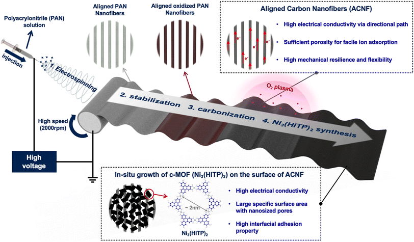
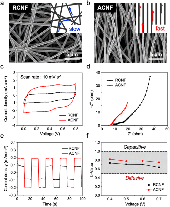
The overall process for the fabrication of the c-MOF/ACNF electrode is illustrated in Fig. 1. ACNFs were prepared by electrospinning a PAN solution under high voltage (12.5 kV) using a high-speed rotary collector (2000 rpm). This approach facilitates a high degree of nanofiber alignment by increasing the speed of the collector, thereby reducing the time during which the charged fibers are randomly arranged on the surface of the drum collector. Subsequently, a stabilization step and a carbonization step were implemented. The as-spun aligned PAN nanofibers turned brown after stabilization, and finally black-colored ACNFs were obtained (Fig. S1†). We found that the surface of ACNFs appears shiny due to the light scattering caused by its high degree of alignment. Subsequently, the ACNF surface was treated with O2 plasma to introduce hydroxyl groups, which served as binding sites for c-MOF seeding layers. The plasma-treated c-MOF was then immersed in Ni(NO3)2·6H2O to incorporate Ni(OH)2, which would act as a metal ion source, on the ACNF surface; subsequently, a HITP·6HCl solution was added as an organic source while O2 was made to flow; finally, the ACNF surface was simultaneously decorated with the c-MOF implementing an in situ growth process that lasted for 4 h to establish strong adhesion between the c-MOF and ACNFs (Fig. S2†).The data reported in Fig. 2 provide information on the morphology and electrochemical properties of CNFs, categorized according to their ordered or disordered structures. As can be evinced from Fig. 2a and S3a,† the RCNFs, which were prepared by electrospinning at a low rotational speed (100 rpm), exhibited a disordered structure. By contrast, the ACNFs, which were manufactured by electrospinning at high rotational speed (2000 rpm), exhibited a quasi-ordered one-directional structure (Fig. 2b and S3b†). The structural alignment of the carbonaceous materials was expected to facilitate electron movement by providing a more efficient pathway in one direction. In particular, the aligned CNFs have lager distance between adjacent nanofiber compared to the disordered structure;39,40 furthermore, as the rotary speed increases during the alignment process, the nanofibers receive a greater pulling force from the collector surface, resulting in a smaller average diameter and consequently higher porosity.38 Through mercury intrusion porosimetry experiments, we determined that the average pore diameter of ACNFs was almost twice as high (60.962 μm) as that of RCNFs (32.169 μm). Furthermore, the porosity of ACNFs was determined to have a value of 86.91%, which is also higher than the corresponding parameter measured for RCNFs, 62.83% (Fig. S4†). To better understand the relationship between structure and porosity, we employed capillary flow porometers. The results substantiated a significant association between the structure of CNFs and the pore diameter (Fig. S5†). The fact that ACNFs exhibited larger and more numerous pores than RCNFs can be attributed to the one-directional alignment process that characterizes the former, which results in it displaying greater internal porosity than RCNFs. The higher porosity of ACNFs is expected in turn to increase the surface area of the fibers within the mat exposed to the electrolyte, so that ion accessibility is enhanced. In particular, for electrodes based on carbonaceous materials such as CNFs, the pore volume, alongside the surface area, is a critical factor in determining the electrodes' specific capacitance, as it corresponds to the ion adsorption sites.
To determine the effectiveness of the alignment of CNFs, we conducted electrochemical experiments in 3 M KCl solution using a three-electrode system whereby ACNFs or RCNFs with a Pt plate electrode holder, a 3 M KCl-filled Ag/AgCl electrode, and Pt mesh were used as the working electrode, reference electrode, and counter electrode, respectively (Fig. S6†). As made evident by the cyclic voltammetry (CV) curves recorded at 10 mV s−1 scan rate, ACNFs exhibited a higher specific capacitance than RCNFs (Fig. 2c); notably, this difference can be attributed to the greater surface area and pore volume of ACNFs. Also, as the scan rate increased, each electrode exhibited EDLC behavior (Fig. S7†). Furthermore, the Nyquist plots presented in Fig. 2d indicate that ACNFs were characterized by lower internal resistance than RCNFs. Because of their lower resistance, ACNFs achieved a current density that was almost twice as high as that achieved by RCNFs under the same applied voltage (Fig. 2e). Similarly, the results of the 4-point probe analysis indicate a notably higher electrical conductivity in ACNFs compared to RCNFs (Fig. S8†).
To investigate the effect of fiber alignment on ion adsorption, the electrochemical behavior of the CNFs was analyzed by determining their b-values (Fig. 2f). Importantly, the b-value can be used as an indicator of how close the electrochemical behavior of the active material is to the ideal capacitive-controlled behavior; specifically, a b-value of 1.0 indicates ideal EDLC behavior, while a value of 0.5 indicates a diffusion-controlled electrochemical reaction. The b-value can be calculated from eqn (1):
| i = avb | (1) |
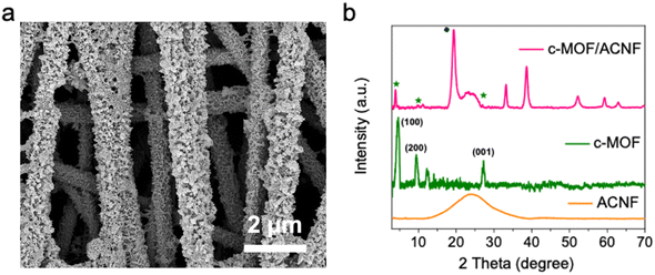
In Fig. 3a and S9,† the scanning electron microscopy (SEM) micrograph of the as-synthesized c-MOF/ACNF composite is reported. The plate-like particles decorating the surface of ACNFs are similar in morphology to the previously reported Ni3(HITP)2 particles.41 To confirm the formation of c-MOF on the mat of ACNFs, X-ray diffractometry (XRD) analysis was performed (Fig. 3b). The XRD pattern of the c-MOF/ACNF composite was compared to those of ACNFs and c-MOF. The XRD pattern of ACNFs included broad peaks, while the powder XRD pattern obtained for c-MOF included distinct peaks at ∼4.7°, 9.5°, and 27.5° values for 2θ, which corresponded to the (100), (200), and (001) planes, respectively.21,42,43 When the surface of ACNFs was decorated with the c-MOF, the XRD diffraction peaks exhibited a slight shift toward higher 2θ values, indicating a reduction in d-spacing of each crystallographic plane of the c-MOF grown on ACNFs. Additionally, the presence of residual peaks suggests the presence of unreacted Ni(OH)2 that was not used for the synthesis of c-MOF.44,45
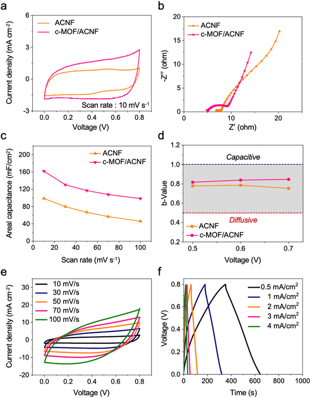
To estimate the synergistic combination of c-MOF and ACNF, we compared the electrochemical performance of the c-MOF/ACNF electrode to that of the ACNFs electrode. As can be evinced from Fig. 4a, the closed area of the CV curves increased in size and exhibited quasi-rectangular shape following the growth of c-MOF on the surface of ACNFs, indicating an increase in the specific areal capacitance due to the high EDLC properties of c-MOF. Additionally, the high electrical conductivity of c-MOFs resulted in the c-MOF/ACNF electrode exhibiting a lower internal resistance than its precursor ACNFs (Fig. 4b).
Based on the obtained results, the areal capacitance of each electrode material was determined at different scan rates using eqn (2):
 | (2) |
Based on this equation, the data reported in Fig. 4c were calculated, according to which the areal capacitance of the c-MOF/ACNF electrode had the values of 161.8, 130.4, 117, 107.9, and 98.4 mF cm−2 at the scan rates of 10, 30, 50, 70, and 100 mV s−1, respectively. Similarly, the areal capacitance of ACNFs was calculated at the above scan rates; the relevant values were 98.7, 79.8, 66.7, 56.7, and 46 mF cm−2, respectively. Overall, therefore, the areal capacitance of ACNFs increased by ∼164%, 163%, 175%, 190%, and 214% at the various scan rates, respectively, because of the electrochemical and surface properties of c-MOF.
To investigate the impact of c-MOF as an active material for EDLCs, the electrochemical behavior of the ACNFs and c-MOF/ACNF electrodes was investigated, and the results of the relevant experiments are presented in Fig. 4d. As can be evinced from this figure, the c-MOF/ACNF electrode exhibited a behavior closer to ideal capacitive control than ACNFs. Furthermore, a deconvolution analysis was conducted to determine the percentage of the peak current associated with each behavior, based on eqn (3):
| i(v) = k1v + k2v1/2 | (3) |
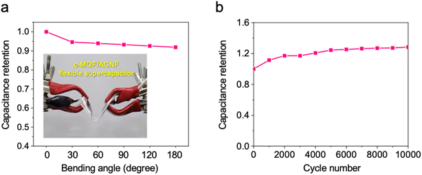
Finally, we demonstrated the feasibility of the use of the c-MOF/ACNF electrode in a flexible supercapacitor by fabricating a pouch-type device and subjecting it to a bending test. Despite undergoing bending (ranging from 0° to 180°), the supercapacitor exhibits only a marginal decrease (∼8.2%) in capacitance at a high bending angle, indicating its remarkable mechanical flexibility and stability (Fig. 5a). Furthermore, the data presented in Fig. 5b indicates that the capacitance of the c-MOF/ACNF electrode initially increased over 5000 cycles due to the gradual activation of the surface and exhibited excellent durability thereafter. After the cycling tests, the c-MOF/ACNF electrode exhibited an almost unchanged morphology, whereby the c-MOF adhered well to the surface of ACNFs (Figure S12†).
3 Conclusions
In this study, we proposed the rational design of c-MOF/ACNF hybrid electrodes for high-performance flexible supercapacitors. c-MOF/ACNF electrodes were successfully fabricated by implementing the electrospinning technique using a high-speed rotary collector followed by the in situ synthesis of c-MOF. The well-ordered structure of ACNFs promoted an efficient electron transfer and effective ion diffusion, resulting in an enhanced electrochemical performance compared to the randomly-ordered CNFs. Furthermore, the synergistic effects of the structural and electrochemical properties of ACNFs and c-MOF, which was demonstrated to have an almost ideal capacitive-controlled behavior, afforded a significant enhancement of the supercapacitor performance (capacitance: 161.8 mF cm−2 at a scan rate of10 mV s−1). Additionally, the c-MOF/ACNF-based supercapacitor that was manufactured exhibited high mechanical flexibility and electrochemical stability. Our findings demonstrate that the rational design of c-MOF/ACNF electrodes can afford the construction of high-performance flexible supercapacitors and provides an effective strategy for designing power sources for next-generation flexible electronics.4 Experimental section
Materials
PAN (Mw: ∼150![[thin space (1/6-em)]](https://www.rsc.org/images/entities/char_2009.gif) 000) and nickel nitrate hexahydrate [Ni(NO3)2–6H2O] were purchased from Sigma-Aldrich, HITP was purchased from Tensus Biotech, ammonium hydroxide (NH4OH) was purchased from Dejung, and N,N-dimethylformamide (DMF; ≥99.8%) was purchased from Daejung.
000) and nickel nitrate hexahydrate [Ni(NO3)2–6H2O] were purchased from Sigma-Aldrich, HITP was purchased from Tensus Biotech, ammonium hydroxide (NH4OH) was purchased from Dejung, and N,N-dimethylformamide (DMF; ≥99.8%) was purchased from Daejung.
Fabrication of RCNFs and ACNFs
RCNFs and ACNFs were prepared by electrospinning followed by carbonization. In detail, 1 g of PAN powder was added to 6 g of DMF, and the mixture thus obtained was vigorously stirred at 80 °C for 6 h to produce a homogeneous solution. The as-prepared solution was transferred into a syringe with a 25 GA metal needle and electrospun on the drum collector applying different rotating speeds depending on the target material (100 rpm for RCNFs and 2000 rpm for ACNFs). Notably, the as-prepared electrospun PAN fibers were first stabilized at 250 °C for 2 h in the air. After stabilization, the fiber mats were carbonized at 900 °C for 2 h in Ar atmosphere to obtain RCNFs and ACNFs.In situ synthesis of c-MOF onto RCNFs and ACNFs
Firstly, the as-prepared RCNFs and ACNFs were treated using an O2 plasma apparatus to introduce hydroxyl groups on the surfaces of the two CNFs. Subsequently, each sample was immersed in a nickel solution obtained dissolving 46 mg of Ni(NO3)2·6H2O in 40 mL of deionized water. Notably, the two obtained mixtures were heated to 80 °C for 1 h, and a HITP·6HCl solution (108 mg) was added dropwise to each of them. Before turning on the flow of O2, 4 mL of NH4OH was added to each reaction mixture. O2 was made to flow through the reaction flask for 2 h under vigorous stirring at 80 °C. Finally, after the O2 flow was turned off, the solution was stirred overnight at 80 °C. After it was prepared, the c-MOF/ACNF composite was washed with deionized water and dried at 60 °C under vacuum conditions overnight.Material characterizations
The microstructures of each electrode material were investigated using SEM. Moreover, crystallographic analysis was performed on the prepared samples in the 4–70° 2θ range using high-resolution XRD with Cu-Kα1 radiation and a Ge (111) monochromator. Mercury intrusion porosimetry (AutoPore IV 9500; Micromeritics Instrument Co., USA) experiments were conducted to measure the density and porosity of RCNFs and ACNFs.Electrochemical characterization
The current densities in RCNFs and ACNFs following the application of a fixed voltage were determined using a Model 8009 Resistivity Test Fixture (Keithley). Electrochemical analyses were conducted using a conventional three-electrode setup where aqueous 3 M KCl was used as the electrolyte. The reference electrode and counter electrode used were an Ag/AgCl electrode and platinum mesh, respectively. As to the working electrodes, 1 × 1 cm2 of RCNFs, ACNFs, c-MOF/RCNF composite material, and c-MOF/ACNF composite material were fabricated without the use of conductive materials and binders. CV and GCD curves were recorded on a ZIVE MP1 (WonATech) within the 0.0–0.8 V voltage range. The overall description of the computational processes is provided in the manuscript.Fabrication of a flexible supercapacitor
A symmetric flexible supercapacitor was fabricated by preparing a sandwich structure composed of a separator impregnated with KCl electrolyte and two pieces of identical c-MOF/ACNF electrodes (7.5 cm × 3.5 cm).Author contributions
D. K., T. G. Y., and J. H. L. contributed equally to this work.Conflicts of interest
The authors declare no competing interests.Acknowledgements
This work was supported by the National Research Foundation of Korea (NRF) grant funded by the Korea government (MSIT) (No. 2022R1F1A1068725 and 2023R1A2C2005617). This study also has been conducted with the supports of the Korea Institute of Industrial Technology as “Development of carbon nanotube pre-dispersion manufacturing technology for next-generation secondary batteries (kitech UI-23-0008)”.References
- C. Guan,
et al., Rational design of metal-organic framework derived hollow NiCo2O4 arrays for flexible supercapacitor and electrocatalysis, Adv. Energy Mater., 2017, 7(12), 1602391 CrossRef
.
- K. J. Samdani,
et al., Morphology-controlled synthesis of Co3O4 composites with bio-inspired carbons as high-performance supercapacitor electrode materials, J. Ind. Eng. Chem., 2019, 74, 96–102 CrossRef CAS
.
- S. Shin and M. W. Shin, Nickel metal–organic framework (Ni-MOF) derived NiO/C@CNF composite for the application of high performance self-standing supercapacitor electrode, Appl. Surf. Sci., 2021, 540, 148295 CrossRef CAS
.
- A. Bazan-Aguilar,
et al., Highly porous reduced graphene oxide-coated carbonized cotton fibers as supercapacitor electrodes, ACS Omega, 2020, 5(50), 32149–32159 CrossRef CAS PubMed
.
- Z. Yang,
et al., Carbon nanotube-and graphene-based nanomaterials and applications in high-voltage supercapacitor: a review, Carbon, 2019, 141, 467–480 CrossRef CAS
.
- N. Jayababu and D. Kim, ZnO nanorods@conductive carbon black nanocomposite based flexible integrated system for energy conversion and storage through triboelectric nanogenerator and supercapacitor, Nano Energy, 2021, 82, 105726 CrossRef CAS
.
- X. Jin,
et al., Nitrogen and Sulfur Co-Doped Hierarchically Porous Carbon Nanotubes for Fast Potassium Ion Storage, Small, 2022, 18(42), 2203545 CrossRef CAS
.
- M. Kim,
et al., Co, Fe and N co-doped 1D assembly of hollow carbon nanoboxes for high-performance supercapacitors, J. Mater. Chem. A, 2022, 10(45), 24056–24063 RSC
.
- R. Reece, C. Lekakou and P. A. Smith, A high-performance structural supercapacitor, ACS Appl. Mater. Interfaces, 2020, 12(23), 25683–25692 CrossRef CAS PubMed
.
- Z. Wen,
et al., Crumpled nitrogen-doped graphene nanosheets with ultrahigh pore volume for high-performance supercapacitor, Adv. Mater., 2012, 24(41), 5610–5616 CrossRef CAS PubMed
.
- K. M. Choi,
et al., Supercapacitors of nanocrystalline metal–organic frameworks, ACS Nano, 2014, 8(7), 7451–7457 CrossRef CAS
.
- W. Li,
et al., Nitrogen-containing carbon spheres with very large uniform mesopores: the superior electrode materials for EDLC in organic electrolyte, Carbon, 2007, 45(9), 1757–1763 CrossRef CAS
.
- B.-H. Kim, K. S. Yang and J. P. Ferraris, Highly conductive, mesoporous carbon nanofiber web as electrode material for high-performance supercapacitors, Electrochim. Acta, 2012, 75, 325–331 CrossRef CAS
.
- L. Zhang,
et al., Flexible hybrid membranes with Ni(OH)2 nanoplatelets vertically grown on electrospun carbon nanofibers for high-performance supercapacitors, ACS Appl. Mater. Interfaces, 2015, 7(40), 22669–22677 CrossRef CAS
.
- A. Knebel and J. Caro, Metal–organic frameworks and covalent organic frameworks as disruptive membrane materials for energy-efficient gas separation, Nat. Nanotechnol., 2022, 17(9), 911–923 CrossRef CAS
.
- S. Yang,
et al., A new post-synthetic polymerization strategy makes metal–organic frameworks more stable, Chem. Sci., 2019, 10(17), 4542–4549 RSC
.
- S. Wang,
et al., Metal–organic framework nanoparticles, Adv. Mater., 2018, 30(37), 1800202 CrossRef PubMed
.
- H. Chen,
et al., Conductive MOF-modified separator for mitigating the shuttle effect of lithium–sulfur battery through a filtration method, ACS Appl. Mater. Interfaces, 2019, 11(12), 11459–11465 CrossRef CAS
.
- D. Sheberla,
et al., High electrical conductivity in Ni3 (2,3,6,7,10,11-hexaiminotriphenylene)2, a semiconducting metal–organic graphene analogue, J. Am. Chem. Soc., 2014, 136(25), 8859–8862 CrossRef CAS PubMed
.
- D. Sheberla,
et al., Conductive MOF electrodes for stable supercapacitors with high areal capacitance, Nat. Mater., 2017, 16(2), 220–224 CrossRef CAS PubMed
.
- D. Cai,
et al., A highly conductive MOF of graphene analogue Ni3(HITP)2 as a sulfur host for high-performance lithium–sulfur batteries, Small, 2019, 15(44), 1902605 CrossRef CAS
.
- L. S. Xie, G. Skorupskii and M. Dincă, Electrically conductive metal–organic frameworks, Chemical reviews, 2020, 120(16), 8536–8580 CrossRef CAS PubMed
.
- H. Furukawa,
et al., The chemistry and applications of metal-organic frameworks, Science, 2013, 341(6149), 1230444 CrossRef PubMed
.
- J. Chmiola,
et al., Anomalous increase in carbon capacitance at pore sizes less than 1 nanometer, science, 2006, 313(5794), 1760–1763 CrossRef CAS PubMed
.
- W. H. Li,
et al., Conductive metal–organic framework nanowire array electrodes for high-performance solid-state supercapacitors, Adv. Funct. Mater., 2017, 27(27), 1702067 CrossRef
.
- X. Huang,
et al., Coating two-dimensional nanomaterials with metal–organic frameworks, ACS Nano, 2014, 8(8), 8695–8701 CrossRef CAS PubMed
.
- P. Falcaro,
et al., Centimetre-scale micropore alignment in oriented polycrystalline metal–organic framework films via heteroepitaxial growth, Nat. Mater., 2017, 16(3), 342–348 CrossRef CAS
.
- L. Wang,
et al., Flexible solid-state supercapacitor based on a metal–organic framework interwoven by electrochemically-deposited PANI, J. Am. Chem. Soc., 2015, 137(15), 4920–4923 CrossRef CAS PubMed
.
- P. Pachfule,
et al., One-dimensional confinement of a nanosized metal organic framework in carbon nanofibers for improved gas adsorption, Chem. Commun., 2012, 48(14), 2009–2011 RSC
.
- J. L. Zhuang,
et al., Patterned deposition of metal-organic frameworks onto plastic, paper, and textile substrates by inkjet printing of a precursor solution, Adv. Mater., 2013, 25(33), 4631–4635 CrossRef CAS PubMed
.
- M. Zhi,
et al., Nanostructured carbon–metal oxide composite electrodes for supercapacitors: a review, Nanoscale, 2013, 5(1), 72–88 RSC
.
- E. Ra,
et al., High power supercapacitors using polyacrylonitrile-based carbon nanofiber paper, Carbon, 2009, 47(13), 2984–2992 CrossRef CAS
.
- Q. Zeng,
et al., Sulfur-bridged bonds boost the conversion reaction of the flexible self-supporting MnS@MXene@CNF anode for high-rate and long-life lithium-ion batteries, ACS Appl. Mater. Interfaces, 2022, 14(5), 6958–6966 CrossRef CAS
.
- C.-K. Hwang,
et al., Perpendicularly stacked array of PTFE nanofibers as a reinforcement for highly durable composite membrane in proton exchange membrane fuel cells, Nano Energy, 2022, 101, 107581 CrossRef CAS
.
- J. Y. Cheong,
et al., Cross-aligned carbon nanofibrous network for efficient and outstanding high-rate Li storage capability, Electrochim. Acta, 2021, 387, 138457 CrossRef CAS
.
- D. Cho,
et al., Focused electric-field polymer writing: toward ultralarge, multistimuli-responsive membranes, ACS Nano, 2020, 14(9), 12173–12183 CrossRef CAS
.
- M. Song,
et al., Flexible and super thermal insulating cellulose nanofibril/emulsion composite aerogel with quasi-closed pores, ACS Appl. Mater. Interfaces, 2020, 12(40), 45363–45372 CrossRef CAS PubMed
.
- M. Kim,
et al., Electrochemical improvement due to alignment of carbon nanofibers fabricated by electrospinning as an electrode for supercapacitor, Carbon, 2016, 99, 607–618 CrossRef CAS
.
- C. Han,
et al., Improved performance of thin-film composite membrane supported by aligned nanofibers substrate with slit-shape pores for forward osmosis, J. Membr. Sci., 2020, 612, 118447 CrossRef CAS
.
- S. B. Mahjour,
et al., Improved cell infiltration of electrospun nanofiber mats for layered tissue constructs, J. Biomed. Mater. Res., Part A, 2016, 104(6), 1479–1488 CrossRef CAS PubMed
.
- D. Nguyen, I. Schepisi and F. Amir, Extraordinary cycling stability of Ni3(HITP)2 supercapacitors fabricated by electrophoretic deposition: cycling at 100
![[thin space (1/6-em)]](https://www.rsc.org/images/entities/char_2009.gif) 000 cycles, Chem. Eng. J., 2019, 378, 122150 CrossRef
000 cycles, Chem. Eng. J., 2019, 378, 122150 CrossRef .
- K. W. Nam,
et al., Conductive 2D metal-organic framework for high-performance cathodes in aqueous rechargeable zinc batteries, Nat. Commun., 2019, 10(1), 4948 CrossRef
.
- S. Zhou,
et al., Cellulose nanofiber@ conductive metal–organic frameworks for high-performance flexible supercapacitors, ACS Nano, 2019, 13(8), 9578–9586 CrossRef CAS PubMed
.
- D. Wang,
et al., NiO nanorings and their unexpected catalytic property for CO oxidation, Nanotechnology, 2006, 17(4), 979 CrossRef CAS PubMed
.
- Z. Wu,
et al., Electrostatic induced stretch growth of homogeneous β-Ni(OH)2 on graphene with enhanced high-rate cycling for supercapacitors, Sci. Rep., 2014, 4(1), 3669 CrossRef PubMed
.
Footnotes |
| † Electronic supplementary information (ESI) available. See DOI: https://doi.org/10.1039/d3na00695f |
| ‡ These authors contributed equally. |
| This journal is © The Royal Society of Chemistry 2024 |

