Ultrabroadband nonlinear enhancement of mid-infrared frequency upconversion in hyperbolic metamaterials†
Congfu
Zhang
 ac,
Zhaolu
Wang
a,
Changchang
Zhang
ac,
Wenjuan
Shi
ac,
Wei
Li
ac,
Ke
Gao
ac and
Hongjun
Liu
*ab
ac,
Zhaolu
Wang
a,
Changchang
Zhang
ac,
Wenjuan
Shi
ac,
Wei
Li
ac,
Ke
Gao
ac and
Hongjun
Liu
*ab
aState Key Laboratory of Transient Optics and Photonics, Xi’an Institute of Optics and Precision Mechanics, Chinese Academy of Science, Xi’an 710119, China. E-mail: liuhongjun@opt.ac.cn
bCollabotative Innovation Center of Extreme Optics, Shanxi University, Taiyuan 030006, China
cUniversity of Chinese Academy of Sciences, Beijing 100084, China
First published on 13th August 2024
Abstract
Metamaterials have demonstrated significant potential for enhancing nonlinear processes at the nanoscale. The presence of narrowband hot-spots and highly inhomogeneous mode-field distributions often limit the enhancement of nonlinear interactions over larger spatial scales. This has posed a formidable challenge in achieving simultaneous enhancement across a broadband spectral range, significantly constraining the potential of photonic nanostructures in enhancing nonlinear frequency conversion. Here, we propose a broadband resonant mode matching method through near-field examinations that supports the multipole modes and enables the development of an ultrabroadband-enhanced 3–5 μm mid-infrared frequency upconversion technique utilizing a hyperbolic triangular pyramidal metasurface. The gap-plasma mode of the hyperbolic metamaterial multilayer system excites narrowly high-order resonances at near-infrared pump light wavelengths, while the slow-light effect generated by the dipoles achieves ultrabroadband near-field enhancement at mid-infrared wavelengths. The symmetry breaking of the triangular structure localizes these resonant modes at the tips, enabling mode-matched modulation at different wavelengths, and thus boosting the nonlinear frequency conversion process. Our approach provides a promising platform for metasurface-based frequency conversion techniques.
New conceptsIn this manuscript, we propose an approach to achieving mode-matched and broadband-enhanced frequency-conversion in triangular pyramid shape of hyperbolic metamaterials (HMMs) through electromagnetic multipole coupling supported by gap-plasma modes. In previous work, it was difficult to achieve broadband enhancement effects and overlaps of field distributions in metasurface resonance modes, especially for sum-frequency-generation processes, where it was a challenge to achieve double-resonances and ensure overlaps of mode fields when the signal and pump wavelengths were significantly different. Our work highlights the gap-plasma modes and multiwavelength hybridization and coupling mechanisms induced between a metal and dielectric, demonstrating that the nanogap system achieves significant near-field enhancement in the near-infrared via electric multipole resonance and exhibits broadband slow-light effects in the mid-infrared, while maintaining optimal ultra-broadband mode-field overlap properties. We discuss that the multipole gap-plasma modes induced by the triangular structure facilitate mode matching, and their symmetry-breaking structure produces strong field localization at the triangle vertices, overcoming previous limitations of mode-field overlap. These modes can be tuned arbitrarily by adjusting the geometry and composition of the elementary antenna, enabling resonance and mode field overlap at any wavelength. These unique features endow the HMMs with significant advantages over other metamaterials, which has implications for nonlinear devices. |
1 Introduction
The nonlinear interaction of light and matter particularly through frequency conversion processes such as second harmonic generation (SHG), third harmonic generation (THG) and sum frequency generation (SFG) is widely utilized in various fields.1,2 Mid-infrared (mid-IR) upconversion technology, which is based on the principle of SFG, converts mid-infrared information to near-infrared (near-IR) or visible light bands. The converted information can be indirectly detected through high-performance near-IR or visible light detectors, enabling the detection of mid-infrared information. Nevertheless, the conventional nonlinear frequency conversion techniques rely on nonlinear crystals, which are constrained by complex phase matching conditions, resulting in a smaller spectral bandwidth. Therefore, it is necessary to find new nonlinear materials or new physical mechanisms to enhance nonlinear interactions.The development of high-quality metasurface nanostructures offers an alternative approach to enhancing the nonlinear frequency conversion process. These artificial materials, composed of sub-wavelength scale structural units, provide substantial advantages in terms of design flexibility and miniaturization.3–6 Metasurfaces allow the customization of the nonlinear response through the engineering of their constituent elements, opening new design possibilities for artificial materials with nonlinear optical properties, including amplitude, phase, and polarization rate. Various implementations using metallic, dielectric, and semiconductor metasurfaces have demonstrated great potential for enhancing nonlinear optical frequency conversion processes on nanoscale metasurfaces. Importantly, the subwavelength thickness of these metasurfaces overcomes the limitations of phase-matching conditions in nonlinear processes. The performance based on resonances, which enables the enhancement of the subwavelength confinement of the localized electromagnetic field in nanostructures, augments many effects in nonlinear photonics and offers new opportunities for subwavelength control of light at the nanoscale.7,8
However, these metasurfaces based on resonance enhancement present three primary challenges:9–14 (i) plasma resonance is always accompanied by ohmic losses compounded by weak penetration of the electric field inside the metal, leading to substantial losses in effective optical enhancement; (ii) near-field enhancement by the resonance modes is limited to a narrow spectral range, making it difficult to achieve broadband effects; and (iii) the near-field enhancement distributions corresponding to resonance modes at different wavelengths are difficult to overlap, which has little effect on harmonic generation.15–17 However, it is a challenge to achieve double resonance and ensure mode field overlap when the signal and pump wavelengths are significantly different for sum frequency generation (SFG) processes, such as mid-infrared upconversion processes. Additionally, second-order nonlinearities are usually present in asymmetric materials at the macroscopic or microscopic level for constructive enhancement in the near-field and the far-field. Currently, there is a lack of a metasurface photonic platform that can simultaneously address these issues.18–20
Recently, hyperbolic metamaterials (HMMs) have garnered significant attention due to their unique electromagnetic properties. These materials, whether naturally occurring or artificially engineered, are typically characterized by layered structures and nanorods.21–23 Their hyperbolic dispersion properties exhibit extreme anisotropy in dielectric constants, supporting propagation modes with high propagation constants, and substantially enhancing the photonic density of states and spontaneous emission. This feature facilitates exceptional light–matter interactions and shows great promise for applications in diverse fields, such as biosensors,24 surface-enhanced Raman spectroscopy,25 hyperlenses,26 negative refraction,27 nanolaser and quantum sources28,29 and beam manipulation.30 Furthermore, HMM nanostructures have demonstrated the ability to enhance nonlinear effects, such as those based on metal nanowire arrays,16,31 metal/dielectric multilayers,32,33 and spheres.34 However, these works are also based on the resonance mechanism, and consequently remain narrow-banded in principle. Based on the slow light effect known as “rainbow trapping”,35–37 HMMs can achieve close to 100% perfect absorption.38–41 Non-resonant enhancement can also be achieved through appropriate material and structural design.
In this work, we propose an approach to achieving mode-matched and broadband-enhanced frequency conversion in HMMs through electromagnetic multipole coupling supported by gap-plasma modes. The hyperbolic cavity is composed of an Au–ZnO multilayer gap system in a triangular pyramid shape with a rich modal structure. Our work highlights the gap-plasmon modes and multi-wavelength resonant hybridization and coupling mechanisms between metals and dielectrics, and the results show that the nanogap system achieves significant near-field enhancement in the near-infrared through electric multipole resonance and exhibits dipole broadband slow-light effects in the mid-infrared, and these resonance-captured higher-order modes and the electric dipole response can be coupled in the presence of normal-incidence plane waves while maintaining the optimal ultrabroadband mode-field overlap properties. We discuss in detail that the multipole gap plasma modes induced by the intrinsic modes of the triangular structure are favorable for mode matching and that their symmetry-breaking structure generates strong field localization at the tip of the triangles, overcoming the previous limitation of non-overlapping the field distributions of the higher-order resonances with those of the fundamental resonances, leading to a mismatch of the mode fields. This tip enhancement overcomes the previous limitation of mode-field mismatch due to non-overlapping field distributions of higher-order resonances and fundamental resonances, while different angles excite a rich variety of modes, allowing for multiple resonances over a larger spectral range. Furthermore, these modes can be tuned arbitrarily by adjusting the geometry (edge lengths, pinch angles, thickness, and number of layers) and composition (metal and dielectric materials) of the elementary antenna, enabling resonance and mode field overlap at any wavelength. Based on these properties, we have realized 3–5 μm ultrabroadband mid-infrared nonlinear frequency upconversion on HMM metasurfaces. The strong nonlinear properties of this structure have been demonstrated through the interaction of a broadband signal light at 3–5 μm with a pump light at 916 nm, generating a strong SFG at 710–780 nm. In addition, the relationship between the nonlinear optical field modes and the overlap integrals of mode field that affect the SFG efficiency is analyzed. Theoretical calculations indicate that the sum frequency process with a maximum conversion efficiency of 2.5 × 10⁻⁵ is achieved using a femtosecond pulsed laser at a pump intensity of 13 MW cm−2. Finally, we demonstrate the weak optical nonlinearity in the HMM for continuous wave (CW) system.
2 Slow light effect and mode matching in triangular prism hyperbolic cavity
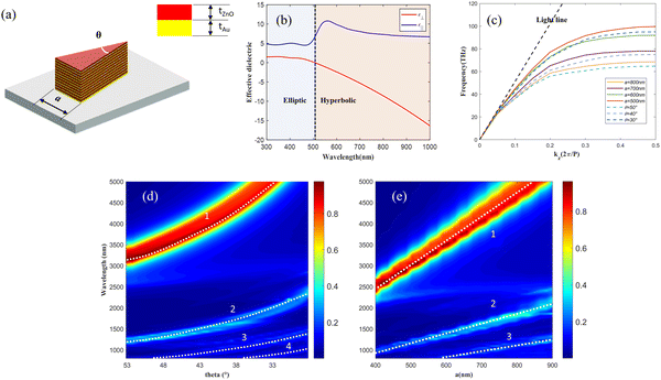
The optical properties of an un-tapered triangular prism HMM structure behaving as a meta-atom of our metasurface are investigated to illustrate the physical origin of mode matching and near-field enhancement. HMMs can be tuned by adjusting the two parameters θ and a as shown in Fig. 1(a), where θ is the angle of the apex of the triangle and a is the length of the bottom edge, and the metasurface consists of alternating Au and ZnO layers in the form of a triangular pyramidal structural array. Au is usually selected as a conductor in the mid-IR waveband for its low losses, while ZnO is chosen for its strong second-order nonlinearity as a dielectric material.42 Generally, the parallel (ε‖) and perpendicular permittivity (ε⊥) of the alternative layers’ nanostructure can be calculated using effective medium theory as follows: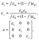 | (1) |
The dispersion profile of the structure is calculated as shown in Fig. 1(c). The wavevector k supported by the structure progressively increases with frequency. As the incident light frequency approaches the cutoff frequency, the dispersion curve flattens, indicating that the group velocity  approaches zero, i.e., the realization of the slow-light effect. The frequency at which slow light occurs shifts correspondingly as the size of the structure varies, when the bottom edge increases, the slow light frequency decreases. Furthermore, the wavelength-dependent absorption spectrum is obtained from the S-parameters by A(λ) = 1 − T(λ) − R(λ) = 1 − |S21|2 − |S11|2, where T(λ) and R(λ) are the wavelength-dependent transmission and reflection, respectively. The absorption spectra with multiple peaks are shown in Fig. 1(d) and (e), and the absorption peak 1 in the spectra of Fig. 1(d) and (e) corresponds to the slow-light effect. This effect shows a red shift as the edge length a increases and the angle decreases, consistent with the previously discussed dispersion curves.
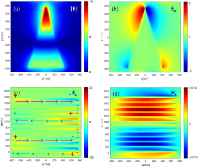
To illustrate the origin of each resonance mode, we use the following geometric parameters for the HMM array as an example: a = 800 nm, θ = 29.5°, tAu = tZnO = 60 nm, the array period is Px = Py = 1800 nm, and the light is normally incident from the upper direction of the structure and is polarized in the y direction and the corresponding electric field distributions for resonance peaks are analyzed. The near-field enhancement of resonance 1 is observed to be concentrated at the structural edges in the direction of the incident light's polarization as shown in Fig. 2(a). This mode indicates a strong electric dipole mode, resulting from surface plasmon polarization (SPP) interactions between the metal and the dielectric. The surface charge at the two ends of the shape (here, base and tip) simply oscillates back and forth between negative and positive, resulting in a localized field enhancement. The asymmetrical triangular structure facilitates the generation of bright modes at the tip, creating a non-zero net moment plasma vertex mode similar to a dipole vertex mode. This phenomenon is evident in the electric field distribution diagrams, where significant near-field enhancement is observed at the tip when light is polarized in the y-direction. Furthermore, the incident light excites two SPP responses on the metal–insulator–metal (MIM) structure in the z-direction, which couple at the dielectric layer to form the gap-plasma mode. Since the gap-plasma modes propagate along the edges of the triangular prism structure and are localized in the z-axis direction, they reflect upon reaching the edges of the MIM structure of the triangular prism. When the edge lengths meet the conditions of the Fabry–Perot effect, kL = mπ − φ (k = 2π/λ and φ are the SPP phase shift accumulated upon reflection at the boundaries), the forward- and backward-propagating gap-plasma below and above the interface interfere in phase, resulting in a standing-wave resonance at a particular wavelength, as indicated by the pink arrow in Fig. 2(c), the current densities at the bottom and at the top of the HMMs are in opposite directions, and the electric field vectors tend to be in opposite directions for the top and bottom nanoparticles, which exhibits a typical configuration of bonding mode. This resonance is characterized as an absorption peak in the spectrum of the MIM structure, effectively forming a Fabry–Perot cavity. Fig. 2(d) shows the calculated magnetic distribution for slow light effect, the cavity modes can be treated as magnetic dipole-like modes with zeroth-order features along the z direction. The non-uniform distribution of these modes within the structure is primarily due to the thickness of the metal plate exceeding the penetration depth of the photons at these wavelengths, which consequently attenuates the magnetic field within the metal.
When the incident light shifts to shorter wavelengths, the HMMs do not exhibit the slow-light phenomenon. Consequently, a portion of the electromagnetic wave is reflected into the air, leading to lower absorption. The analysis of the absorption spectral field distribution is shown in Fig. 3, and the multipolar decomposition in the ESI† (Fig. S2) shows that the absorption peak at mid-infrared wavelengths has mainly electric and magnetic dipole contributions, which is the same physical mechanism of generation that we analyzed earlier, while the resonance peaks at short wavelengths are mainly contributed by electric quadrupoles, magnetic quadrupoles, and electric octupoles. These higher-order resonances arise from the Mie's resonance of the dielectric, which is a consequence of the delay of light in structural directions comparable to the wavelength. This leads to inadequate separation of positive and negative surface charges, reducing the field absorption and localization capabilities. The resonances disappear when the structure size is significantly smaller than the wavelength, as indicated by the white dashed lines in Fig. 1(d) and (e). We find that resonant excitation of higher-order modes leads to a significant decrease in the electric dipole moment of the structure, indicating that the dipole modes are not excited and that there is an energy flow between the excited dipole modes and these higher-order modes in the structure. In this case, the energy stored in the higher-order modes is distributed over the metasurface plane, a process that can be visualized as light trapping therein. Additionally, all these higher-order modes exhibit surface charge distributions at the tip that are opposite, resulting in enhanced tip effects for all higher-order modes. This leads to improved mode overlap with the dipole modes, which contrasts with previous circular and square structures in the ESI† (Fig. S1). Since the surface polarization charges are accumulated at the corner of the prism, the maximum electric field enhancement is achieved at the corner.
However, the slow-light effect facilitated by such triangular prisms is inherently narrow-banded, limiting their effectiveness to high absorption near specific cutoff wavelengths (slow light) corresponding to the structure size. To address this limitation, the following section introduces triangular pyramidal structures with tapered directions that offer ultrabroadband nonlinearities. These tapered structures are designed to support broadband absorption effects while maintaining better mode overlap at the resonance peak wavelengths.
3 Ultrabroadband enhancement in triangular pyramidal nanostructure
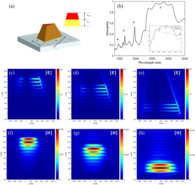
To achieve ultrabroadband absorption and near-field enhancement in the 3–5 μm upconversion signal wavelength range, a triangular pyramidal structure with a gradient width is proposed to enable the structure to support a broad range of widths. The structural parameters of the triangular pyramidal HMM are optimized, as detailed in Fig. 4(a). These parameters are specifically tailored to enhance the mode-field overlap and near-field enhancement of the mid-infrared signal light and the near-infrared pump light. The absorption spectra of the triangular pyramidal structure exhibit multiple absorption peaks within across an ultrabroad absorption band, as shown in Fig. 4(b). Notably, the absorption of the structure exceeds 90% within the 3–4.5 μm wavelength range, demonstrating the HMM structure's exceptional remarkable ultrabroadband absorption capabilities.Furthermore, we analyze how the narrowband slow light effect enables broadband “rainbow trapping”. The electric field distributions for three specific points are shown in Fig. 4, denoted as A, B, and C within the high absorption band 1. These points correspond to the wavelengths of the maximum field enhancement, maximum absorption, and the last absorption peak, respectively. Fig. 4(c), (d), and (e) illustrate the field distributions of |E| (normalized to the incident light) in the y-z plane, with the maximum field enhancement factor ranging from 30 to 53. The analysis of the electric field distribution |E| and the magnetic field distribution Hx in the y-z plane reveals how different wavelengths of light concentrate in distinct parts of the triangular structure. At the shorter wavelength λA = 3160 nm, the energy is predominantly localized in the upper part of the triangular pyramid. As the wavelength increases, the local field enhancement progressively shifts towards the larger dimensions of the structure. In contrast, at a longer wavelength of λC = 4930 nm, the energy is trapped in the lower part. The local distribution of the field is consistent with the physical effects observed in triangular prisms, where the absorption mechanism is attributed to the coupling of the slow light modes to the gap-plasma. When the positively incident broadband light reaches the cutoff wavelength of the respective structure, it no longer propagates downward, but instead propagates upward, forming a resonant cavity in the z direction. This coupling effect controls the optical field localization of different wavelengths of light in this structure, contributing to its broadband absorption and field enhancement capabilities. The triangular pyramidal structure ensures efficient excitation of all components of the magnetic dipole, enabling “rainbow trapping”. Because of the small size of the top, the dispersion of the corresponding TM0 modes is similar to that of the vacuum free modes in the broadband range, as shown in Fig. 1(c). This allows for better couple with the incident light. The adjustability of the triangular pyramidal structure allows for broadband enhancement due to the weakly coupled resonance exhibited by the slow light mode. This feature makes the structure versatile and suitable for a wide range of optical applications across different light frequencies.
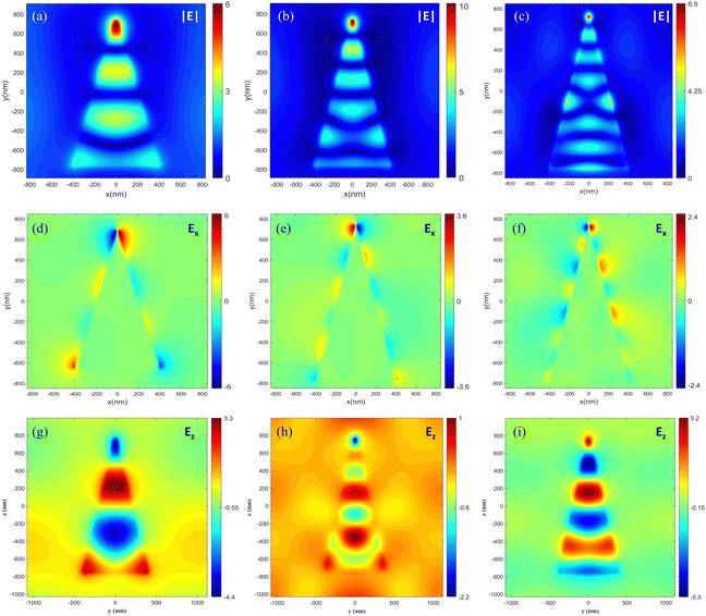
The wavelengths corresponding to the absorption peaks 2, 3, and 4 as shown in Fig. 4(b) are 1932 nm, 1327 nm, and 916 nm, respectively. We analyze the optical effect of the 4th absorption peak at a wavelength of 916 nm and its mode-field overlap with the slow-light effect band and the near-field distributions at the remaining wavelengths are shown in the ESI† (Fig. S3 and S4). Fig. 5 shows the electric field |E| distributions of the 916 nm light within the 4th, 6th, and 12th ZnO layers, respectively, which correspond to the locations of the maximum near-field localization at the three wavelengths of the slow-light effect band observed previously. The formation of these local field distributions is attributed to the hybridization of electromagnetic multipoles, following the principle in the triangular prism. Which leads to significant tip enhancement effects and improved mode field overlap with electric dipole generation. It indicates that the tapered triangular prism structure retains the higher-order modes characteristic of the original triangular prism.
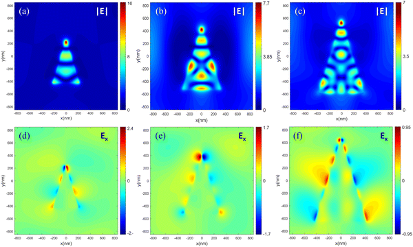 | ||
| Fig. 5 Electric field |E| and Ez distributions of 916 nm in different positions of the triangle structure. (a) and (d) 4th layer of ZnO; (b) and (e) 6th layer of ZnO; (c) and (f) 12th layer of ZnO. | ||
Moreover, the ultrabroadband properties are further investigated. The distinctive tapered shape of the HMM leads to closely spaced resonances within the spectra, with each layer exhibiting its own resonance wavelength. As the number of HMM layers increases, these resonances broaden and eventually merge, forming a broadband resonance group characterized by strong absorption peaks. Moreover, as the number of HMM layers increases, these resonances broaden and eventually merge, forming a broadband resonance group characterized by strong absorption peaks. The development of these absorption bands is attributed to the mutual coupling between optical modes in different tapered HMM layers. This is supported by the absorption spectra of three tapered HMM arrays with varying layer counts, as depicted in Fig. 6(a)–(c), which illustrates the absorption curves and near-field enhancement relative to the wavelength of incident light for different layers, with black line representing the absorption curve and red line representing the curve of maximum electric near-field enhancement. When the directions of the top and bottom are fixed, increasing the number of layers results in smaller changes in the size of each layer. This leads the system towards an adiabatic transition, which will achieve a complete absorption. Furthermore, the field enhancement declines as the wavelength increases within the range where the slow-light effect occurs. This is likely due to charge confinement in structures with a smaller edge length, which would lead to greater field enhancement.
 | ||
| Fig. 6 Absorption and near-field enhancement of E for TP-HMMs with varying pairs of Au/ZnO layers. The number of Au/ZnO pairs is (a) 4, (b) 7, (c) 20, respectively. | ||
4 Nonlinear emissions from triangular pyramidal hyperbolic metasurface
The investigation delves into the nonlinear frequency conversion properties based on the optical properties of the triangular pyramidal hyperbolic metasurface. The choice of 916 nm for the pump light used is twofold: first, 916 nm corresponds to an absorption peak of the structure, yielding robust field enhancement; second, it facilitates the production of the sum frequency spectrum between 700 nm and 800 nm when combined with the 3–5 μm mid-infrared light. This wavelength range is advantageous for detecting upconversion light, given the availability of high-performance detectors.Before the calculation, the second-order nonlinearities in materials and structure are to be analyzed. The electric field distributions show that the Ez field is mainly enhanced in the metal and dielectric structures, while the Ez field is almost entirely distributed in ZnO, in addition, the enhancement of the Ex field mainly occurs in the air slit, and there is almost no obvious Ex local field enhancement effect inside the metal and dielectric materials, which corresponds to the surface effect of the second-order nonlinearities of Au,43 even though the effective action volume is lower than that of ZnO, and the 6 mm symmetry of the ZnO structure supporting the second-order nonlinear magnetization tensor χ15 = χ15 = χ31 = χ32 and χ33.42 It is assumed that the Z-component primarily contributes to the second-order nonlinear generation. Structurally, the triangular design introduces symmetry breaking in the y-direction with in the x-y plane. Additionally, localized symmetry-breaking along the metal–dielectric interface disrupts inversion symmetry perpendicularly, both of which enhance the second-order nonlinearity of the structure. For a detailed analysis of nonlinear upconversion generation and the effective nonlinear permittivity, please refer to the ESI† (Sections S6 and S11).
To validate the second-order nonlinearity of the structure, the power density of the 916 nm pump is 13.3 MW cm−2, and the signal is set at three wavelengths—3160 nm, 3700 nm, and 4930 nm—using the same power density as the pump, with a pulse width of 200 fs to ensure temporal overlap of the signal and pump.
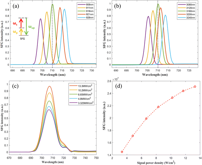
The wavelength of the pump light is tuned from 906 to 926 nm in steps of 5 nm, while maintaining the pump light fixed at 3160 nm. Fig. 7(a) shows the SFG emission from 706 nm to 714 nm, with a maximum at 710 nm, corresponding to a signal light at 3160 nm. The SFG intensity gradually decreases with the increase of the signal wavelength after the maximum at 710 nm. Subsequently, we simulate the SFG by varying the signal light wavelength from 3080 nm to 3240 nm in steps of 40 nm while maintaining signal light fixed at 916 nm [see Fig. 7(b)]. The results shown in Fig. 7(a) and (b) indicate that the optimized SFG intensity occurs when the metasurface is excited by a pump light at 916 nm and a signal light at 3160 nm. This behavior is explained by our previous analysis of the linear optical properties of the metasurface, i.e., the near-field enhancement of the excitation lights.
Fig. 7(c) presents the spectrum of upconversion light at various signal light power densities, based on which the relationship between the conversion efficiency and the power density of the signal can be derived, as illustrated in Fig. 7(d). The SFG conversion efficiency is calculated using eqn (2):
 | (2) |
Since the signal light of different wavelengths is located in different positions inside the structure, we focus on calculating the maximum field enhancement position of each wavelength. The normalized near-field distributions of the different upconversion light generated are shown in Fig. 8. To evaluate the overlapping properties of the mode fields, the concept of overlap integrals is introduced as follows:
 | (3) |
The overlap integral γ represents the tendency of energy to flow from the signaling and pumping optical modes to the sum-frequency optical modes, which is integrated over the nonlinear volume V. To maximize the integral, the product of the three wave electric fields must add up conductively and not offset, meaning that the modes excited at the three wavelengths must exhibit the correct symmetry. The optimal nanostructure for second harmonic emission represents a compromise between the absorption at the signal, pump, sum frequency light, and the ability for the microscopic sources to combine constructively.
Considering the main nonlinear electric field component Ez in the structure, the mode field overlap at different wavelengths is analyzed. The Ez distribution in the 4th ZnO layer presented, as along with its corresponding Ez distribution for the 3160 nm signal light, the 916 nm pump light and the 710 nm sum frequency light as depicted in Fig. 9. In the polarization direction of the wave (i.e., the y-direction), Esz and Epz are antisymmetric modes, while Eupz is symmetric. This symmetry increases the sum of the integrand functions over a nonlinear volume, resulting in the maximum overlap integral. The analysis of the overlap integrals for 3700 nm and 4930 nm is provided in the ESI† (Fig. S7).
 | ||
| Fig. 9 The distribution of Ez electric field in the x-y plane of the triangular pyramidal structure in layer 4 at wavelengths (a) 3160 nm; (b) 916 nm; (c) 710 nm. | ||
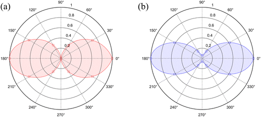
Subsequently, the dependence of the SFG emission on the polarization angle of the incident light is investigated, demonstrating the nontrivial polarization dependence on the SFG process, as presented in Fig. 10. The wavelength of the pump light is fixed at λp = 916 nm, and the signal light is fixed at λs = 3160 nm. The polarization plot of λs =3700 nm, and 4930 nm are available in ESI† Fig. S13 and S14. For 3160 nm. The maximum SFG emission is observed when the pump light is polarized at 0° from the signal light.
The maximum SFG emission intensity excited by a CW laser is investigated, which is numerically presented in the ESI† (Fig. S15(a)), and Fig. S15(b) and (c) displays the spectrum of the maximum and minimum SFG obtained when excited by CW with Fourier transformation. Efficiency levels around 2.21 × 10⁻⁵ are observed for a signal at 3160 nm wavelength with CW intensities of 1.3 kW cm−2. As the signal light intensity is further reduced, the minimum observable SFG power for 3160 nm is approximately 10.9 pW for an average input signal power of 43 μW, at which point, the pump intensity is 133 W cm−2, and the conversion efficiency is 2.55 × 10⁻⁷. It is noted that the upconversion light becomes indistinguishable from noise when the signal light intensity is further reduced.
5 Conclusion
In conclusion, we propose a mode matching and field enhancement method based on higher-order plasma mode coupling, underpinning the demonstration of an efficient ultrabroadband mid-infrared SFG with hyperbolic hybrid metasurface. An analysis of the near-field enhancement properties of a triangular prism and a triangular pyramidal metasurface structure and the coupling and hybridization of different modes is presented. This metasurface achieves broadband enhancement of the mid-infrared signal by supporting broadband absorption of slow-light rainbow trapping. The triangular symmetry-breaking properties and gap-plasma modes realize the tip enhancement property, thereby enabling strong coupling between higher-order and dipole modes and improving mode-field overlap between the near-IR and mid-IR optical fields. When the metasurface is illustrated by a pump light of 916 nm and a signal light of 3–5 μm simultaneously, the maximum field enhancement factor is 53-times, facilitating effective SFG. The maximum conversion efficiency is 2.5 × 10⁻⁵ for both signal and pump pulses with intensities around 13.3 MW cm−2 through numerical calculation. Additionally, SFG on these metasurfaces is demonstrated using a continuous-wave signal light. Overall, this study presents a promising platform for developing ultrabroadband nonlinear coupling of light and matter, and provides a new opportunity for metasurface nonlinear frequency conversion technology.Data availability
The data supporting this article have been included as part of the ESI.† The software used in this simulation is Lumerical FDTD 2020 R2.1 Material refractive index is derived from the web site, https://refractiveindex.info/.Conflicts of interest
The authors declare no conflicts of interest.Acknowledgements
This work is supported by the National Natural Science Foundation of China (NFSC) (Project ID 61975232)References
- A. S. Ashik, C. F. O'Donnell, S. C. Kumar, M. Ebrahim-Zadeh, P. Tidemand-Lichtenberg and C. Pedersen, Mid-infrared upconversion imaging using femtosecond pulses, Photonics Res., 2019, 7(7), 783–791 CrossRef.
- R. Camacho-Morales, D. Rocco, L. Xu, V. F. Gili, N. Dimitrov, L. Stoyanov, Z. H. Ma, A. Komar, M. Lysevych, F. Karouta, A. Dreischuh, H. H. Tan, G. Leo, C. De Angelis, C. Jagadish, A. E. Miroshnichenko, M. Rahmani and D. N. Neshev, Infrared upconversion imaging in nonlinear metasurfaces, Adv. Photonics, 2021, 3(3), 10 Search PubMed.
- D. Neshev and I. Aharonovich, Optical metasurfaces: new generation building blocks for multi-functional optics, Light: Sci. Appl., 2018, 7, 5 CrossRef.
- K. Achouri and C. Caloz, Design, concepts, and applications of electromagnetic metasurfaces, Nanophotonics, 2018, 7(6), 1095–1116 Search PubMed.
- M. Rahmani, G. Leo, I. Brener, A. V. Zayats, S. A. Maier, C. De Angelis, H. Tan, V. F. Gili, F. Karouta, R. Oulton, K. Vora, M. Lysevych, I. Staude, L. Xu, A. E. Miroshnichenko, C. Jagadish and D. N. Neshev, Nonlinear frequency conversion in optical nanoantennas and metasurfaces: materials evolution and fabrication, Opto-Electron. Adv., 2018, 1(10), 12 Search PubMed.
- M. Kauranen and A. V. Zayats, Nonlinear plasmonics, Nat. Photonics, 2012, 6(11), 737–748 CrossRef.
- P. Vabishchevich and Y. Kivshar, Nonlinear photonics with metasurfaces, Photonics Res., 2023, 11(2), B50–B64 CrossRef.
- G. Li, S. Zhang and T. Zentgraf, Nonlinear photonic metasurfaces, Nat. Rev. Mater., 2017, 2(5), 14 Search PubMed.
- S. Kruk, M. Weismann, A. Y. Bykov, E. A. Mamonov, I. A. Kolmychek, T. Murzina, N. C. Panoiu, D. N. Neshev and Y. S. Kivshar, Enhanced Magnetic Second-Harmonic Generation from Resonant Metasurfaces, ACS Photonics, 2015, 2(8), 1007–1012 CrossRef.
- P. P. Vabishchevich, S. Liu, M. B. Sinclair, G. A. Keeler, G. M. Peake and I. Brener, Enhanced Second-Harmonic Generation Using Broken Symmetry III-V Semiconductor Fano Metasurfaces, ACS Photonics, 2018, 5(5), 1685–1690 CrossRef.
- M. W. Klein, C. Enkrich, M. Wegener and S. Linden, Second-harmonic generation from magnetic metamaterials, Science, 2006, 313(5786), 502–504 CrossRef.
- V. Caligiuri, L. Pezzi, A. Veltri and A. De Luca, Resonant Gain Singularities in 1D and 3D Metal/Dielectric Multilayered Nanostructures, ACS Nano, 2017, 11(1), 1012–1025 CrossRef PubMed.
- Q. C. Yuan, L. Fang, H. L. Fang, J. T. Li, T. Wang, W. Q. Jie, J. L. Zhao and X. T. Gan, Second Harmonic and Sum-Frequency Generations from a Silicon Metasurface Integrated with a Two-Dimensional Material, ACS Photonics, 2019, 6(9), 2252–2259 CrossRef.
- A. Krasnok, M. Tymchenko and A. Alù, Nonlinear metasurfaces: a paradigm shift in nonlinear optics, Mater. Today, 2018, 21(1), 8–21 CrossRef.
- A. Noor, A. R. Damodaran, I. H. Lee, S. A. Maier, S. H. Oh and C. Ciracì, Mode-Matching Enhancement of Second-Harmonic Generation with Plasmonic Nanopatch Antennas, ACS Photonics, 2020, 7(12), 5333–5340 CrossRef.
- H. Harutyunyan, G. Volpe, R. Quidant and L. Novotny, Enhancing the Nonlinear Optical Response Using Multifrequency Gold-Nanowire Antennas, Phys. Rev. Lett., 2012, 108(21), 4 CrossRef.
- G. Grinblat, M. Rahmani, E. Cortés, M. Caldarola, D. Comedi, S. A. Maier and A. V. Bragas, High-Efficiency Second Harmonic Generation from a Single Hybrid ZnO Nanowire/Au Plasmonic Nano-Oligomer, Nano Lett., 2014, 14(11), 6660–6665 CrossRef.
- R. C. Camacho-Morales, L. Xu, H. Z. Zhang, S. T. Ha, L. Krivitsky, A. I. Kuznetsov, M. Rahmani and D. Neshev, Sum-Frequency Generation in High-Q GaP Metasurfaces Driven by Leaky-Wave Guided Modes, Nano Lett., 2022, 8, 6141–6148 CrossRef.
- N. Nefedkin, A. Mekawy, J. Krakofsky, Y. R. Wang, A. Belyanin, M. Belkin and A. Alù, Overcoming Intensity Saturation in Nonlinear Multiple-Quantum-Well Metasurfaces for High-Efficiency Frequency Upconversion, Adv. Mater., 2023, 35(34), 11 CrossRef PubMed.
- A. Mekawy and A. Alù, Giant midinfrared nonlinearity based on multiple quantum well polaritonic metasurfaces, Nanophotonics, 2021, 10(1), 667–678 Search PubMed.
- S. Indukuri, J. Bar-David, N. Mazurski and U. Levy, Ultrasmall Mode Volume Hyperbolic Nanocavities for Enhanced Light-Matter Interaction at the Nanoscale, ACS Nano, 2019, 13(10), 11770–11780 CrossRef.
- N. Maccaferri, Y. Q. Zhao, T. Isoniemi, M. Iarossi, A. Parracino, G. Strangi and F. De Angelis, Hyperbolic Meta-Antennas Enable Full Control of Scattering and Absorption of Light, Nano Lett., 2019, 19(3), 1851–1859 CrossRef.
- N. Maccaferri, A. Zilli, T. Isoniemi, L. Ghirardini, M. Iarossi, M. Finazzi, M. Celebrano and F. De Angelis, Enhanced Nonlinear Emission from Single Multilayered Metal-Dielectric Nanocavities Resonating in the Near-Infrared, ACS Photonics, 2021, 8(2), 512–520 CrossRef.
- D. Lu, J. J. Kan, E. E. Fullerton and Z. W. Liu, Enhancing spontaneous emission rates of molecules using nanopatterned multilayer hyperbolic metamaterials, Nat. Nanotechnol., 2014, 9(1), 48–53 CrossRef PubMed.
- K. V. Sreekanth, Y. Alapan, M. ElKabbash, E. Ilker, M. Hinczewski, U. A. Gurkan, A. De Luca and G. Strangi, Extreme sensitivity biosensing platform based on hyperbolic metamaterials, Nat. Mater., 2016, 15(6), 621 CrossRef PubMed.
- Z. W. Liu, H. Lee, Y. Xiong, C. Sun and X. Zhang, Far-field optical hyperlens magnifying sub-diffraction-limited objects, Science, 2007, 315(5819), 1686 CrossRef.
- J. Valentine, S. Zhang, T. Zentgraf, E. Ulin-Avila, D. A. Genov, G. Bartal and X. Zhang, Three-dimensional optical metamaterial with a negative refractive index, Nature, 2008, 455(7211), 376–379 CrossRef PubMed.
- K. C. Shen, C. T. Ku, C. Hsieh, H. C. Kuo, Y. J. Cheng and D. P. Tsai, Deep-Ultraviolet Hyperbolic Metacavity Laser, Adv. Mater., 2018, 30(21), 7 CrossRef PubMed.
- K.-C. Shen, C. Hsieh, Y.-J. Cheng and D. P. Tsai, Giant enhancement of emission efficiency and light directivity by using hyperbolic metacavity on deep-ultraviolet AlGaN emitter, Nano Energy, 2018, 45, 353–358 CrossRef.
- X. Yin, H. Zhu, H. J. Guo, M. Deng, T. Xu, Z. J. Gong, X. Li, Z. H. Hang, C. Wu, H. Q. Li, S. Q. Chen, L. Zhou and L. Chen, Hyperbolic Metamaterial Devices for Wavefront Manipulation, Laser Photonics Rev., 2019, 13(1), 11 Search PubMed.
- G. Marino, P. Segovia, A. V. Krasavin, P. Ginzburg, N. Olivier, G. A. Wurtz and A. V. Zayats, Second-Harmonic Generation from Hyperbolic Plasmonic Nanorod Metamaterial Slab, Laser Photonics Rev., 2018, 12(2), 9 Search PubMed.
- J. H. Li, G. W. Hu, L. N. Shi, N. He, D. Q. Li, Q. Y. Shang, Q. Zhang, H. G. Fu, L. L. Zhou, W. Xiong, J. G. Guan, J. Wang, S. L. He and L. Chen, Full-color enhanced second harmonic generation using rainbow trapping in ultrathin hyperbolic metamaterials, Nat. Commun., 2021, 12(1), 6 CrossRef PubMed.
- B. Wood, J. B. Pendry and D. P. Tsai, Directed subwavelength imaging using a layered metal-dielectric system, Phys. Rev. B: Condens. Matter Mater. Phys., 2006, 74(11), 115116 CrossRef.
- W. Y. Wu, L. L. Fan, W. B. Zang, X. Yang, P. Zhan, Z. Chen and Z. L. Wang, Second harmonic generation enhancement from a nonlinear nanocrystal integrated hyperbolic metamaterial cavity, Opt. Express, 2017, 25(18), 21342–21348 CrossRef PubMed.
- H. F. Hu, D. X. Ji, X. Zeng, K. Liu and Q. Q. Gan, Rainbow Trapping in Hyperbolic Metamaterial Waveguide, Sci. Rep., 2013, 3, 6 Search PubMed.
- N. I. Landy, S. Sajuyigbe, J. J. Mock, D. R. Smith and W. J. Padilla, Perfect Metamaterial Absorber, Phys. Rev. Lett., 2008, 100(20), 207402 CrossRef CAS PubMed.
- T. D. Dao, K. Chen, S. Ishii, A. Ohi, T. Nabatame, M. Kitajima and T. Nagao, Infrared Perfect Absorbers Fabricated by Colloidal Mask Etching of Al-Al2O3-Al Trilayers, ACS Photonics, 2015, 2(7), 964–970 CrossRef CAS.
- H. X. Deng, C. J. Mathai, S. Gangopadhyay, J. Gao and X. D. Yang, Ultra-broadband infrared absorption by tapered hyperbolic multilayer waveguides, Opt. Express, 2018, 26(5), 6360–6370 CrossRef CAS PubMed.
- Y. X. Cui, K. H. Fung, J. Xu, H. J. Ma, Y. Jin, S. L. He and N. X. Fang, Ultrabroadband Light Absorption by a Sawtooth Anisotropic Metamaterial Slab, Nano Lett., 2012, 12(3), 1443–1447 CrossRef CAS PubMed.
- J. Zhou, A. F. Kaplan, L. Chen and L. J. Guo, Experiment and Theory of the Broadband Absorption by a Tapered Hyperbolic Metamaterial Array, ACS Photonics, 2014, 1(7), 618–624 CrossRef CAS.
- F. Ding, Y. Jin, B. R. Li, H. Cheng, L. Mo and S. L. He, Ultrabroadband strong light absorption based on thin multilayered metamaterials, Laser Photonics Rev., 2014, 8(6), 946–953 CrossRef.
- G. Wang, G. T. Kiehne, G. K. L. Wong, J. B. Ketterson, X. Liu and R. P. H. Chang, Large second harmonic response in ZnO thin films, Appl. Phys. Lett., 2002, 80(3), 401–403 CrossRef CAS.
- F. X. Wang, F. J. Rodríguez, W. M. Albers, R. Ahorinta, J. E. Sipe and M. Kauranen, Surface and bulk contributions to the second-order nonlinear optical response of a gold film, Phys. Rev. B: Condens. Matter Mater. Phys., 2009, 80(23), 233402 CrossRef.
Footnote |
| † Electronic supplementary information (ESI) available. See DOI: https://doi.org/10.1039/d4nh00240g |
| This journal is © The Royal Society of Chemistry 2024 |

