First-row transition metal carbide nanosheets as high-performance cathode materials for lithium–sulfur batteries†
Imran
Muhammad‡
 a,
Shehzad
Ahmed‡
b,
Zhen
Yao
a,
Danish
Khan
c,
Tanveer
Hussain
a,
Shehzad
Ahmed‡
b,
Zhen
Yao
a,
Danish
Khan
c,
Tanveer
Hussain
 d and
Yang-Gang
Wang
 *a
*a
aDepartment of Chemistry and Guangdong Provincial Key Laboratory of Catalytic Chemistry, Southern University of Science and Technology, Shenzhen, Guangdong 518055, China. E-mail: wangyg@sustech.edu.cn
bCollege of Physics and Optoelectronic Engineering, Shenzhen University, Guangdong 518060, China
cCollege of New Materials and New Energies, Shenzhen Technology University, Shenzhen 518118, Guangdong, China
dSchool of Science and Technology, University of New England, Armidale, New South Wales 2351, Australia
First published on 17th November 2023
Abstract
Despite the prodigious potential of lithium–sulfur (Li–S) batteries as future rechargeable electrochemical systems, their commercial implementation is hindered by several vital issues, including the shuttle effect and sluggish migration of lithium-polysulfides leading to rapid capacity fading. Here, we systematically investigate the potential of first-row two-dimensional transition metal carbides (TMCs) as sulfur cathodes for Li–S batteries. The adsorption strength of lithium-polysulfides on TMCs is induced by the amount of charge transfer from the former to the latter and the proposed periodic relationship between sulfur in Li2S and 3d-transition metals. Our findings show that the VC nanosheet possesses immense anchoring potential and exhibits a comparatively low migration energy barrier for lithium-ion and Li2S molecules. Additionally, we report ab initio molecular dynamics simulations for lithiated polysulfide species anchored on a TMC-based model with a liquid-electrolyte medium. The microscopic reaction mechanism, revealed by the evolution of the reaction voltage during lithiation, demonstrates that the dissolution of high-order lithium-polysulfides in the electrolytes can be prevented due to their robust interaction with TMC-based cathode materials. These appealing features suggest that TMCs present colossal performance improvements for anchoring lithium-polysulfides, stimulating the active design of sulfur cathodes for practical Li–S batteries.
1. Introduction
The lithium–sulfur (Li–S) battery is considered to be one of the most promising emerging electrochemical devices for next-generation energy storage applications due to its high theoretical capacity (1675 mA h g−1) and energy density (2567 W h kg−1), both of which are several times higher than those of commercially used lithium-ion batteries (LIBs).1–3 The high abundance and environmentally friendly nature of sulfur, with the involvement of multiple-electron-transfer electrochemistry (16Li + S8 → 8Li2S) in a sulfur cathode that provides intrinsic protection from overcharging, suggest that Li–S batteries are more appealing than current LIBs.4,5 Nevertheless, the commercialization of Li–S batteries is obstructed by several difficulties, such as the poor conductivity of sulfur (5 × 10⁻³⁰ S cm−1 at 25 °C) and the rigorous volume change of sulfur during lithiation and delithiation processes, leading to the pulverization of electrode materials.6–8 Besides, the dissolution of lithium-polysulfides (Li2Sn) in the electrolyte results in a shuttle effect, and the deposition of Li2Sn on the anode materials causes poor charge–discharge cycling performance, lower coulombic efficiency (CE) and fast capacity loss of Li–S batteries.9,10 Over the previous decade, numerous strategies have been developed to alleviate the dissolution of polysulfides and enhance their diffusion during cycling to improve the kinetics of electrodes. In particular, extensive research has demonstrated that conductive carbon-based nanostructures (i.e., graphene,11 graphene oxide,12 hollow carbon spheres,13 carbon nanotubes,14 and macro/meso/microporous15 carbon) can greatly mitigate the limitation of low conductivity and colossal volumetric change.16 Such carbonaceous materials substantially improve the capacity of electrochemical cells, while the weak physical interaction between the non-polar materials and polar Li2Sn species leads to significant capacity decay during the cycling process.17 Following this, heteroatom doping with carbon-based materials has been adopted to anchor the Li2Sn molecules strongly. For instance, carbon nitride nanostructures are reported as being the most effective anchoring materials to confine the Li2Sn molecules and circumvent their dissolution. Nitrogen in carbon-based materials reacts as a Lewis base and interacts actively with Lewis acids of lithium-polysulfides.18,19 On the other hand, reactive oxygen in graphene oxide is reported as an effective material for immobilizing Li2Sn.20 Apart from heteroatom-doped porous carbon-based21 materials, some metal sulfides22 and oxides23,24 exhibit polar surfaces and active chemical interactions with polysulfides; however, the low electrical conductivities of most materials result in the slow conversion of polysulfides and cause capacity fading during long cycling. Recently, transition metal–organic frameworks, transition metal carbonitrides,25 and transition metal-doped C6N2![[thin space (1/6-em)]](https://www.rsc.org/images/entities/char_2009.gif) 26 have theoretically been reported as high-performance cathode materials for Li–S batteries with minimal structural distortion. Transition metal carbide (TMC) nanostructures exhibit excellent stabilities and high electrical conductivities and hold great potential as advanced sulfur cathodes by boosting stability and cycling life at high sulfur loading.27,28 However, theoretical research to understand the electrochemical performance of TMCs in Li–S batteries has rarely been explored.
26 have theoretically been reported as high-performance cathode materials for Li–S batteries with minimal structural distortion. Transition metal carbide (TMC) nanostructures exhibit excellent stabilities and high electrical conductivities and hold great potential as advanced sulfur cathodes by boosting stability and cycling life at high sulfur loading.27,28 However, theoretical research to understand the electrochemical performance of TMCs in Li–S batteries has rarely been explored.
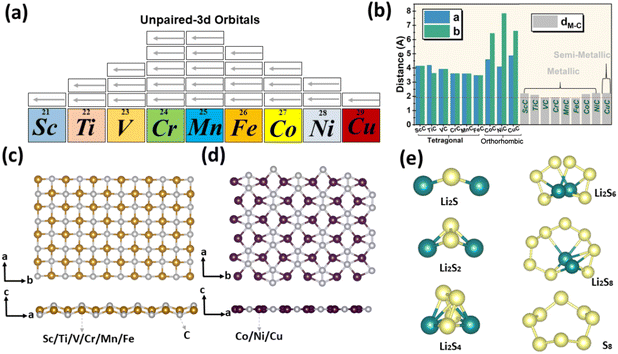
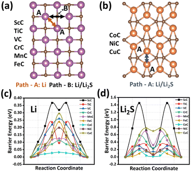
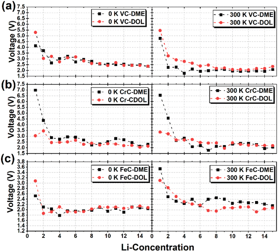
In this work, we have systematically investigated the anchoring competence of first-row TMC nanostructures, including ScC, TiC, VC, CrC, MnC, FeC, CoC, NiC, and CuC, for Li2Sn; the primary structures of these materials have been collected from previously reported literature.29–37 The variation in unoccupied d orbitals of first-row TMs (see Fig. 1(a)) directly influences their interactions with Li2Sn clusters. These TMC-based nanomaterials exhibit different crystal structures, where ScC, TiC, VC, CrC, MnC, and FeC have tetragonal and CoC, NiC, and CuC have orthorhombic structures, as presented in Fig. 1(b, c and d), with the detailed geometric structures of TMCs being shown in Fig. S1 of the ESI.† The results of AIMD simulations reveal that all these structures exhibit excellent thermal stabilities (see Fig. S2 of the ESI†). As shown in Fig. S3,† ScC, TiC, VC, CrC, MnC, FeC, CoC, and NiC nanosheets exhibit inherent metallic natures; however, CuC is semi-metallic with a band gap of 0.015 eV. Moreover, the low diffusion barrier energy of Li ions and Li2S clusters on TMC nanostructures results in fast mobility, demonstrated by the excellent rate performance of Li–S batteries. Moreover, we use ab initio molecular dynamics (AIMD) simulations to study the structural evolution of lithiated polysulfides anchored on VC, CrC, and FeC cathode materials with liquid electrolytes such as dimethoxyethane (DME) and 1,3-dioxolane (DOL). The voltage profiles at 0 K and 300 K are analyzed, demonstrating various reaction mechanisms, where the low Li concentration corresponds to high voltage, while increasing the concentration leads to a plateau in the voltage profile. The bond of the Li ion with the O atom of the liquid electrolyte is observed, which results in the dissolution of lithium-polysulfides in the electrolyte; however, TMC-based anchoring materials strongly bind the polysulfides and constrain the shuttling effect.
2. Method
DFT calculations are conducted within the Perdew–Burke–Ernzerhof (PBE) functional of the generalized gradient approximation (GGA)38 by employing the Vienna ab initio simulation package (VASP).39 The electron–ion interaction is described using the projector augmented wave (PAW) method.40,41 A plane-wave cutoff energy of 500 eV and the long-range dispersion correction by the Grimme DFT-D3 method42 are included for van der Waals interactions. A force criterion of 0.01 eV Å−1 and an energy criterion of 10−4 eV are used to optimize atomic positions and lattice constants. The Hubbard-U method43,44 is adopted to correct the strong correlation interaction between d orbitals of transition metals with the U values of 6.0, 4.2, 3.35, 3.7, 3.9, 5.3, 3.32, 6.2, and 4.0 for ScC, TiC, VC, CrC, MnC, FeC, CoC, NiC, and CuC, respectively.45,46 For the adsorption and diffusion of the Li ion and Li2S, rectangular 2 × 3 × 1 supercells and a vacuum distance of 15 Å for TMCs are considered. The interaction between the Li2S and TMC nanostructures is analyzed using eqn (1), which describes the adsorption energy (Eads):| Eads = Esubstrate + ELi2S − E(substrate+Li2S) | (1) |
| EvdW = Ewith-vdWads − Ewithout-vdWads | (2) |
To reveal the charge transfer by the Li2S molecule to the substrate, Bader charge integration47,48 is employed, and the atomic interaction is studied by utilizing the atom-in-molecule (AIM)49 analysis. Topological positioning of electron densities is performed by AIM analysis. The wave functions are extracted from the calculations performed using the Gaussian 09 code50 by employing the PBEPBE functional and 6-311G(d,p) basis set to compute the electron density (ρ) and the corresponding Laplacian (∇2ρ) values at the bond critical points (BCPs). Then, the extracted wave function files (.wfn) are exported to the Multiwfn code51 to plot the BCPs and to obtain the electron density and corresponding Laplacian values for the intermolecular bonds. In addition, chemical bonding analysis is accomplished using the crystal orbital Hamilton population (COHP)52–55 method to determine the bonding interaction, implemented in the Local Orbital Basis Suite Towards Electronic-Structure Reconstruction (LOBSTER).56,57 The diffusion pathways and the corresponding diffusion barriers of Li ions and Li2S molecules on TMC nanostructures are calculated using the climbing image nudged elastic band (CI-NEB) method.58Ab initio molecular dynamics (AIMD) simulations are conducted at 300 K for 10 ps with a time step of 1 fs for determining the interaction of polysulfides on the TMCs by employing the 8S8 + 15 Li + 8DME/DOL model. We adopted a simulated annealing method to anneal the models for obtaining stable systems for analyzing the reaction voltage with increasing concentrations of Li ions in lithium-polysulfides.
3. Results and discussion
3.1 Anchoring Li2Sn on monolayer TMCs
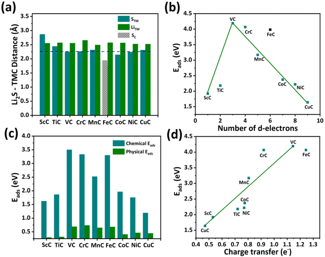
The anchoring capability of TMCs is studied by systematically investigating the adsorption of short-chain Li2S on ScC, TiC, VC, CrC, MnC, FeC, CoC, NiC, and CuC nanostructures. In this study, different adsorption configurations are examined, and the most energetically stable site for Li2S molecules on TMCs is considered. The adsorption of Li2S molecules on TMCs is determined by considering three kinds of bond distances (labeled as STM, LiTM, and SC), where STM and LiTM are the bond distances of S and Li from the TM, and SC is the bond distance between S and the C atom (see Fig. 2(a)). In tetragonal TMCs, the large value of STM for ScC indicates the dominance of LiTM bonding, while the lower value of STM for VC and CrC reveals the dominance of STM bonding. The STM bond distance for VC is calculated to be 2.25 Å, suggesting a strong binding strength between the Li2S molecules. In FeC, SC bonding is more dominant, with a value of 1.80 Å, resulting in a strong interaction between the Li2S molecule and the C atom of the substrate. In orthorhombic TMCs, a gradual increase in STM and a decrease in LiTM are found, indicating that the strength of the LiTM bond rises from CoC to NiC.We have calculated the adsorption energy to understand the scheme for the adsorption of Li2S molecules on TMC substrates (Eads). Fig. 2(b) shows the linear periodic relationship between Eads and the number of d-electrons; the energy linearly increases from ScC to VC and decreases from VC to CuC except for FeC, where the sulfur of Li2S is bonded with a carbon atom. Among all the TMC-based materials, VC exhibits the most energetically stable Eads with a value of 4.25 eV. The three valence electrons in V account for the highest Eads in VC, leading to the most stable adsorption of the Li2S molecule. TMCs, including ScC and TiC, have an insufficient number of valence electrons, which restricts their chemical bonding with sulfur. In the case of TMCs from CrC to CuC, the number of valence electrons is larger than 4, and Eads decreases gradually with an increasing number of valence electrons. This phenomenon can also be explained by considering the decrease in unoccupied electrons from Cr to Cu, which prevents the STM bond formations; for instance, Cu possesses only one unoccupied d-electron to interact with the Li2S molecule, which results in low adsorption energy. Such periodic relationships of Eads with the number of d-electrons in TMs have also been reported in TMSs59 and TMNs.60 Moreover, the Eads of the Li2S molecule on the FeC nanostructure does not follow a linear relationship because of the strong bonding of sulfur with a carbon atom instead of the Fe atom, which results in a higher adsorption energy of 3.98 eV. Furthermore, the strength of the chemical and physical vdW interaction of the Li2S molecule on all TMC-based nanomaterials has been studied, as shown in Fig. 2(c). The chemical interaction dominates for Li2S molecules, confirming that short-order lithium-polysulfides are chemically confined to all TMC materials. In addition, the trend of the chemical interaction of Li2S is analogous to the total adsorption energy on TMCs. Following the trend of total adsorption energy, VC has a stronger chemical interaction with Li2S molecules compared to all the TMCs, suggesting it is a promising anchoring material for Li–S battery applications.
The strength of the interaction between TMCs and the Li2S cluster can be elucidated through molecular orbital theory. In TMCs, the d orbitals exhibit a degree of degeneracy of 5, comprising 3 low-energy t2g orbitals and 2 high-energy eg orbitals. The eg orbitals are involved in σ bonding (occupied) and σ* antibonding (unoccupied) interactions with the p orbitals of carbon. Conversely, the t2g orbitals participate in antibonding interactions due to their differing orbital orientations compared to the carbon p orbitals. Furthermore, the presence of t2g non-bonding orbitals is observed in ScC–MnC. The occupation of these non-bonding orbitals near the Fermi level contributes to the Eads. In the scenario of ScC–VC, the bonding state of the TM–S interaction remains partially unoccupied due to the absence of electron occupation in the t2g orbitals. Notably, an increase in the occupancy of t2g orbitals correlates with enhanced adsorption energies when interacting with the Li2S cluster. In the case of VC–MnC, the TM–S antibonding state becomes populated by an electron, reducing the Eads. However, in the transition from MnC–CuC, the bonding state of the TM–S interaction tends not to be fully occupied, contributing to a decrease in the Eads.
Furthermore, Bader charge integration is employed to evaluate the charge transfer from Li2S to TMC-based substrates. The charge transfer by the Li2S molecule is plotted versus the total adsorption energies for all the TMC substrates, as shown in Fig. 2(d). Charge transfer from the Li2S cluster to substrates linearly increases with the strength of adsorption energy, and the highest charge transfers of 1.25 e− and 1.15 e− are found for FeC and VC nanostructures, respectively.
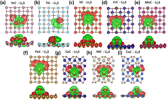
The charge density difference between the Li2S molecule and TMC nanostructures is studied with an iso-surface value of 0.004 e per Bohr3, where the green and red colors show the charge gain and loss, respectively (see Fig. 3). The charge transfers (Δρ) can be presented as follows:
| Δρ = ρ(TMC + Li2S) − ρ(TMC) − ρ(Li2S)(3) | (3) |
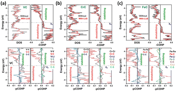
As shown in Fig. S4–S12,† the orbital-projected densities of states of all these materials reveal that the bonding states of TMC nanostructures are highly contributed to by the p orbital of C and d orbital of the transition metal (TM). Based on our results, we found that TMC nanostructures exhibit strong chemical interactions with the Li2S cluster, and the strength of adsorption energies is collectively associated with the number of d orbitals of the transition metal. Compared to pristine TMCs, a prominent change has been observed in the PDOS of Li2S adsorbed on TMCs, indicating the charge transfer and the orbital interaction between d orbitals of TMs and p orbitals of S atoms. In the case of FeC, the overlapping of orbitals of C and S atoms is found near the Fermi level; therefore, the FeC nanostructure does not follow the general trend of interactions, which is because of d electrons in the TM. Fig. 4 shows the combination of the TDOS and COHP analyses providing a comprehensive understanding of these intriguing structural stability and electronic properties of these TMCs. The COHP analysis is conducted for monolayers of VC, CrC, and FeC to gain insights into the bonding interactions within these systems. Remarkably, all three monolayers exhibited remarkable stability in their configurations. The COHP analysis highlighted strong and well-defined bonding interactions among the constituent atoms. Specifically, pCOHP analysis provides valuable insights into the bonding interactions that underlie the remarkable stability of the pristine VC, CrC, and FeC monolayers, while in the case of Li2S adsorption, V–V, V–Li, V–S, C–C, C–Li, Li–S, and Cr–Cr, Cr–C, Cr–Li, Cr–S, C–C, C–Li, C–S, Li–S interactions contribute to the overall structural integrity and cohesiveness of the respective monolayers. However, the pCOHP analysis of Li2S cluster-adsorbed FeC demonstrates that Fe–Fe and Fe–C interactions exhibit instability. This comprehensive assessment of stability patterns sheds light on the intricate web of bonding interactions within the monolayers, providing crucial insights into their structural viability and potential applications. In addition, energy-integrated COHP (ICOHP) provides an estimate of the bond energy (the more the negative value, the stronger the bonding strength). The calculated –ICOHP values at the EF are 2.571, 2.523, and 2.553 eV for CrC, FeC and VC bonding with Li2S-adsorbed monolayers, while the –ICOHP values are 2.750, 2.807, and 2.665 eV for CrC, FeC and VC monolayers. Besides, the COHP of CrC, FeC, and VC bonding is very negative for both clean and Li2S-adsorbed layers, indicating strong covalence. The calculated ICOHP bonding presents a similar trend to that of CrC, FeC and VC bonding after Li2S substitution.
To understand the nature of the interaction and bonding strength of Li2S with the TMCs during the storage process, we have investigated using atom-in-molecule (AIM) analysis.49 AIM analysis verifies the strength of interactions among adsorbed Li2S and TMCs. Eight criteria has been proposed to confirm electrostatic intermolecular interactions.53,54 Among these, three fundamental criteria were considered by Lipkowski et al.,61 namely, the presence of Laplacian (∇2ρ), electron density (ρ), and BCPs. Specifically, the values of ρ and ∇2ρ must be in the range of 0.002–0.035 and 0.02–0.14 au for the existence of electrostatic interactions between the storage material and the species to be stored. The AIM graphs for ionic interaction at adsorption sites are presented in Fig. S14,† while the values of ρ and ∇2ρ are given in Table 1. These values for Li2S@VC, Li2S@CrC, and Li2S@FeC are much higher, i.e., 0.0352 to 0.0301 au for ρ and 0.0537 to 0.041 au for ∇2ρ, respectively. According to the AIM analysis, the values of ρ and ∇2ρ are in the range of stronger intermolecular interactions, which shows the stronger interaction of Li2S with the TMCs, especially for VC, CrC, and FeC. The AIM results agree with the adsorption energies, that VC, CrC, and FeC have a higher affinity to anchor at the surface of TMCs.
| Systems | ScC | TiC | VC | CrC | MnC | FeC | CoC | NiC | CuC |
|---|---|---|---|---|---|---|---|---|---|
| ρ | 0.0121 | 0.0133 | 0.0352 | 0.0311 | 0.0174 | 0.0301 | 0.0152 | 0.0149 | 0.0100 |
| ∇ 2 ρ | 0.0238 | 0.0242 | 0.0537 | 0.0463 | 0.0301 | 0.0411 | 0.0298 | 0.0261 | 0.0194 |
Furthermore, the interactions between high-order lithium-polysulfides, including Li2S4, Li2S6, and Li2S8 clusters, and all TMC nanostructures were also studied, and the calculated Eads are listed in Table 2. Based on the Eads of high-order lithium-polysulfides, the anchoring performance of TMCs is classified into two groups: (1) TMCs that strongly anchor Li2Sn (n = 4, 6, and 8) including ScC (1.91–0.85 eV), TiC (1.95–1.36 eV), VC (3.19–2.09 eV), CrC (3.16–1.89 eV), MnC (2.52–2.44 eV), FeC (2.61–0.81 eV), and CoC (2.73–1.73 eV), exhibiting energies higher than those of commonly used electrolytes, such as dimethoxyethane (DME) and 1,3-dioxolane (DOL), which can efficiently avoid the dissolution of higher-order polysulfides in electrolytes; and (2) TMCs with weak anchoring capabilities, including NiC (1.47–0.77 eV) and CuC (0.99–0.61 eV) exhibiting low Eads, which may result in the dissolution of higher-order polysulfides in liquid electrolytes. The adsorption energies of short- and long-chain lithium-polysulfides of different theoretically reported anchoring materials are listed in Table S1 Of the ESI.† The moderate Eads of high-order lithium-polysulfides on most TMCs are beneficial for the charge–discharge process of Li–S batteries, causing extremely high energies for such clusters, leading to the decomposition of lithium polysulfides.
| Cluster | ScC | TiC | VC | CrC | MnC | FeC | CoC | NiC | CuC |
|---|---|---|---|---|---|---|---|---|---|
| Li2S4 | 1.91 | 1.95 | 3.19 | 3.16 | 2.46 | 2.61 | 2.73 | 1.47 | 0.99 |
| Li2S6 | 1.45 | 1.81 | 2.28 | 1.59 | 2.52 | 1.88 | 1.73 | 0.90 | 0.64 |
| Li2S8 | 0.85 | 1.36 | 2.09 | 1.89 | 2.44 | 0.81 | 1.58 | 0.77 | 0.61 |
In addition, the catalytic properties of VC for the sulfur reduction reaction (SSR) were studied, where the SSR process is given below:
| S8* + 16Li + 2e → Li2S8* + 14Li | (4) |
| Li2S8* + 14Li + 2e → Li2S6* + Li2S2 + 12Li | (5) |
| Li2S6* + Li2S2 + 12Li + 2e → Li2S4* + 2Li2S2 + 10Li | (6) |
| Li2S4* + 2Li2S2 + 10Li + 2e → Li2S2* + 3Li2S2 + 8Li | (7) |
| Li2S2* + 3Li2S2 + 8Li + 8e → Li2S* + 7Li2S | (8) |
The schematic presentation of the transition of S8 into Li2S and the Gibbs free energies (ΔG) for all steps are shown in Fig. S15 of the ESI.† The negative values of ΔG in each term determine the exothermic reaction and the ΔG2, ΔG3, and ΔG4 values are only 0.71 eV, 1.31 eV, and 1.11 eV, respectively, indicating that SRR is thermodynamically feasible.
3.2 Diffusion of lithium and lithium-polysulfides on TMCs
The cycling performance of the sulfur cathode is analyzed by considering the migration paths and the corresponding energy barriers for the Li ion and the Li2S cluster on all TMC-based anchoring materials, as shown in Fig. 5 and Fig. S16 of the ESI.† In the case of tetragonal TMCs, two diffusion paths are found for the mobility of the Li ion from site A to the neighboring site A/B (path-A/path-B). ScC (TiC) exhibits a low diffusion energy barrier through path-A with a bimodal energy curve; however, VC, CrC, MnC, and FeC show fast migration through path-B with a unimodal energy curve as shown in Fig. 4(c). On the other hand, one diffusion path with the lowest energy is found in the orthorhombic structures of CoC, NiC, and CuC from site A to the nearest site A. Among all the TMC nanostructures, CoC has the smallest energy barrier of 0.03 eV, and VC, CrC, and FeC also have low Li-ion diffusion barriers of 0.25, 0.11, and 0.23 eV, respectively. All the TMC structures show low diffusion barriers for Li ions compared to graphene (0.30 eV), TMS (0.10–0.63 eV),59 and TMN (0.16–0.57 eV)60 materials for anchoring the sulfur cathode. The fast migration of the Li ion on TMCs can considerably expedite the redox reaction, significantly improving the rate performance of Li–S batteries.Moreover, the diffusion barrier of Li2S decomposition also plays an important role in the charge–discharge process of Li–S batteries. Therefore, the diffusion of Li2S on TMCs has also been studied, as presented in Fig. 5(d). The Li2S cluster has low diffusion energy barriers on TMCs, and their values are partially correlated with the adsorption energies. The lowest energy paths for ScC, TiC, VC, CrC, MnC, FeC, and CoC, NiC, CuC nanostructures are shown in Fig. 5(a) and (b), corresponding to bimodal energy curves for all TMCs. The barrier energies for ScC, TiC, VC, CrC, MnC, FeC, CoC, NiC, and CuC are 1.45, 0.32, 0.30, 0.41, 0.68, 0.16, 0.18, 0.19, and 0.77 eV, respectively. These findings verify that VC, CrC, and FeC exhibit the most potential as desirable sulfur cathodes for Li–S batteries.
3.3 Electrolyte and lithium-polysulfide interactions on TMCs
We first studied the strength of adsorption energies of ScC, TiC, VC, CrC, MnC, FeC, CoC, NiC, and CuC substrates and a single short-chain Li2S species in dimethoxyethane (DME) and 1,3-dioxolane (DOL) electrolyte environments. The plot of adsorption energies is shown in Fig. S17,† which demonstrates an analogous trend to the adsorption energies of TMCs and Li2S in a vacuum. Our results show that the adsorption energy strength of TMCs and Li2S possesses a periodic relationship with the unoccupied 3d orbitals in a vacuum and the electrolytes.Next, AIMD simulations were conducted to probe the interaction between the DME/DOL electrolyte and a lithium-polysulfide cluster adsorbed on three desirable TMCs, including VC, CrC, and FeC. Fig. 6 and Fig. S18 and S19† summarize six models of fifteen lithium atoms and eight molecules of S8 exposed to 8DOL/DME electrolyte molecules on the supercell of TMC (VC, CrC, and FeC) substrates. In particular, the interactions between the VC, CrC, FeC, and S8 molecules are observed and the reaction is noticed between the lithium atoms and DOL/DME electrolyte during the 10 ps AIMD simulations.
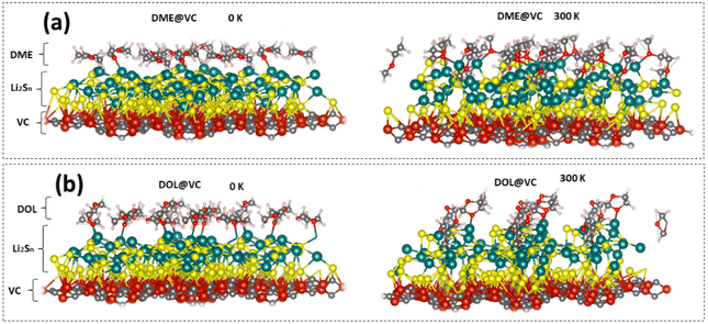 | ||
| Fig. 6 Geometric illustration of 8S8 + 15Li + 8DME anchored on the supercell of the VC-based model at (a) 0 K and (b) 300 K during AIMD calculations for 10 ps at a temperature of 300 K. | ||
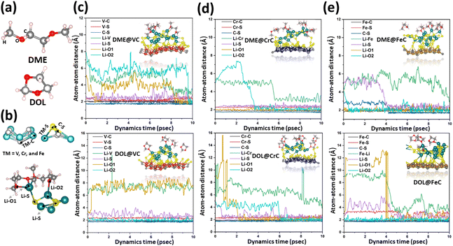
The relaxed geometric structures of DME and DOL are presented in Fig. 7(a) along with a schematic of various bonds, which describes the interaction of Li2Sn clusters with DOL/DME molecules and TMC-based cathode materials. Fig. 7(c), (d), and (e) illustrate the atom-to-atom distance for evaluating the stability of TMCs and the interactions of Li2Sn with DME/DOL electrolytes on VC, CrC, and FeC, respectively. We found that VC, CrC, and FeC exhibit excellent stability by maintaining the V–C/Cr–C/Fe–C bond distance at around 1.90 Å with the interfaces of DME and DOL electrolytes. In addition, strengthening interactions are found between the TMs and sulfur atoms by considering a small bond distance of 2.28 Å for V, 2.25 Å for Cr, and 2.35 Å for Fe. Moreover, sulfur atoms strongly interact with carbon atoms in TMCs with bond lengths of 1.76 Å, 1.73 Å, and 1.68 Å for VC, CrC, and FeC, respectively; smaller S–C bonds in the case of FeC describe a more active interaction, which is in accordance with our previous discussion. In addition, the Li–S bonds are in the range of 2.20–2.60 Å, 2.21–2.57 Å, and 2.38–2.64 Å anchored on VC, CrC, and FeC, respectively, demonstrating the feasible interaction of Li2Sn clusters on the cathode materials. The lithium atoms in Li2Sn interact with O atoms of electrolyte molecules, where the bond distances Li–O1(O2) are 2.22 (1.79 Å), 2.14 (2.03 Å), and 1.91 (1.84 Å) for the DME interface on VC, CrC, and FeC, respectively. In comparison, Li–O1(O2) is calculated to be 2.16 (1.79 Å), 2.26 (2.05 Å), and 2.28 (2.12 Å) in the case of the DOL electrolyte interface. Previously, the decomposition of DME/DOL electrolytes was reported with the Li2Sn clusters and predicts that electrolyte molecules decompose into methane and ethane. The evolution of such gases is adverse to the performance of Li–S batteries. On the other hand, the AIMD simulations for 10 ps at 300 K for TMC cathode materials describe the view that DME/DOL molecules feasibly interact with Li2Sn without producing unsought gases.62 TMC-based anchoring materials not only actively interact with S8 clusters but also contribute to the stability of systems by avoiding the evolution of gases. To further justify the stability of such systems, the AIMD calculation has been carried out for 20 ps at 300 K, which demonstrates that 8S8 + nLi + 8DME/DOL adsorbed on VC, CrC, and FeC shows tremendous structural stabilities by avoiding the hazardous gases as shown in Fig. S20 of the ESI.†
3.4 Lithiation of S8 clusters anchored on TMC sheets with the interface of the electrolyte
Next, the lithiation of S8 clusters adsorbed on the three considered TMCs (VC, CrC, and FeC) was determined by randomly increasing the number of Li ions. Our model consists of 8S8 + nLi + 8DME/DOL adsorbed on VC/Cr/FeC. While adding each Li ion, the system is equilibrated for 2 ps using AIMD calculations and the simulated annealing technique. Thermal stabilities for the increasing concentration of Li ions in 8S8 + nLi + 8DME anchored on the supercell of the VC/CrC/FeC nanosheet are evaluated by plotting the fluctuations in potential energies during AIMD calculations for 2 ps at a temperature of 300 K, as shown in Fig. S21–S26.†The reaction voltages are determined using the following equation:
| V = (E(model + nLi) − E(model) − nE(Li))/xe | (9) |
4. Conclusion
In this study, we systematically scrutinized the anchoring potential of TMC nanostructures as sulfur cathodes for Li–S batteries through DFT and AIMD calculations. The strength of adsorption energies for Li2S molecules on TMCs is closely related to the number of unoccupied 3d electrons of the TM atom. The adsorption energy is induced by charge transfer from the S atom to the TM atom in all TMCs, while for FeC, the C–S bonding contributes more effectively. Moreover, the Li ion and the Li2S cluster exhibit low migration energy barriers in TMC-based nanostructures, which are essential for the rate performance of Li–S batteries. Compared to the other TMCs, VC, CrC, and FeC nanosheets have the capability to bind the long-chain lithium sulfide cluster. Moreover, we monitored AIMD simulations for the 8S8 + 15Li + 8DME/DOL model anchored on VC/CrC/FeC to analyze the interaction of TMC cathodes with Li2Sn and DME/DOL electrolytes. In this model, low concentrations of Li ions correspond to high voltage; however, the increasing concentration of Li ions leads to a voltage plateau due to enhanced Li–Li repulsive forces. Lithium atoms in Li2Sn molecules form a bond with the O atom of the DME/DOL molecules, which may lead to the dissolution of polysulfides, while VC, CrC, and FeC cathodes play a significant role by efficiently binding the lithium-polysulfides and constraining the shuttling effect. This study provides stable designs with high electrochemical performance of TMC-based materials for Li–S battery applications.Conflicts of interest
There are no conflicts of interest to declare.Acknowledgements
This work was financially supported by the National Key R&D Program of China (No. 2022YFA1503102), the NSFC (No. 22022504) of the China Science Technology and Innovation Commission of Shenzhen Municipality (No. JCYJ20220818100410023, KCXST20221021111207017), the Guangdong “Pearl River” Talent Plan (No. 2019QN01L353) and the Guangdong Provincial Key Laboratory of Catalysis (No. 2020B121201002).References
- A. Manthiram, Y. Fu, S. Chung, C. Zu and Y. Su, Chem. Rev., 2014, 114, 11751–11787 CrossRef CAS PubMed.
- Q. Qu, T. Gao, H. Zheng, Y. Wang, X. Li, X. Li, J. Chen, Y. Han, J. Shao and H. Zheng, Adv. Mater. Interfaces, 2015, 2, 1500048 CrossRef.
- I. Muhammad, S. Ahmed, H. Cao, A. Mahmood and Y.-G. Wang, J. Phys. Chem. C, 2023, 127, 1198–1208 CrossRef CAS.
- L. Borchardt, M. Oschatz and S. Kaskel, Chem. – Eur. J., 2016, 22, 7324–7351 CrossRef CAS PubMed.
- C. Li, Y. Li, Y. Fan, F. Wang, T. Lei, W. Chen, A. Hu, L. Xue, J. Huang, C. Wu, C. Yang, Y. Hu and Y. Yan, Small, 2022, 18, 2106657 CrossRef CAS.
- Z. Wei and Y. Ren, InfoMat, 2020, 2, 483–508 CrossRef CAS.
- Y. Hu, W. Chen, T. Lei, Y. Jiao, J. Huang, A. Hu, C. Gong, C. Yan, X. Wang and J. Xiong, Adv. Energy Mater., 2020, 10, 2000082 CrossRef CAS.
- X. Li, M. Gu, S. Hu, R. Kennard, P. Yan, X. Chen, C. Wang, M. J. Sailor, J. Zhang and J. Liu, Nat. Commun., 2014, 5, 1–7 Search PubMed.
- I. Muhammad, U. Younis, H. Xie, Y. Kawazoe and Q. Sun, Adv. Theory Simul., 2020, 3, 1–7 Search PubMed.
- J. Huang, Q. Zhang and F. Wei, Energy Storage Mater., 2015, 1, 127–145 CrossRef.
- Y. Zhang, Z. Gao, N. Song, J. He and X. Li, Mater. Today Energy, 2018, 9, 319–335 CrossRef.
- C. Wang, X. Wang, Y. Yang, A. Kushima, J. Chen, Y. Huang and J. Li, Nano Lett., 2015, 15, 1796–1802 CrossRef CAS.
- C. Ye, L. Zhang, C. Guo, D. Li, A. Vasileff and H. Wang, Adv. Funct. Mater., 2017, 27, 1702524 CrossRef.
- W. Yeol, E. Mei, J. Sang, D. Kang, B. Jin and S. Mun, Energy, 2020, 212, 118779 CrossRef.
- S. Li, B. Jin, X. Zhai, H. Li and Q. Jiang, ChemistrySelect, 2018, 3, 2245–2260 CrossRef CAS.
- Q. Xiao, Carbon Energy, 2021, 3, 271–302 CrossRef CAS.
- Q. Zhang, Y. Wang, Z. W. Seh, Z. Fu, R. Zhang and Y. Cui, Nano Lett., 2015, 15, 3780–3786 CrossRef CAS.
- N. Yamsang, J. Sittiwong, P. Srifa and B. Boekfa, Appl. Surf. Sci., 2021, 565, 150378 CrossRef CAS.
- Y. Qie, J. Liu, S. Wang, S. Gong and Q. Sun, Carbon, 2018, 129, 38–44 CrossRef CAS.
- S. Yuan, Z. Guo, L. Wang, S. Hu, Y. Wang and Y. Xia, Adv. Sci., 2015, 2, 1500071 CrossRef.
- T. Li, C. He and W. Zhang, J. Energy Chem., 2021, 52, 121–129 CrossRef CAS.
- T. Lei, W. Chen, J. Huang, C. Yan, H. Sun and C. Wang, Adv. Energy Mater., 2017, 7, 1601843 CrossRef.
- F. Liu, Q. Xiao, H. B. Wu, F. Sun, X. Liu, F. Li, Z. Le, L. Shen, G. Wang, M. Cai and Y. Lu, ACS Nano, 2017, 11, 2697–2705 CrossRef CAS.
- Z. Chang, H. Dou, B. Ding, J. Wang, Y. Wang, X. Hao and D. R. Macfarlane, J. Mater. Chem. A, 2017, 5, 250–257 RSC.
- C. He, Z. F. Qi and W. X. Zhang, J. Alloys Compd., 2023, 934, 167786 CrossRef CAS.
- C. He, Y. Liang and W. Zhang, ACS Appl. Mater. Interfaces, 2022, 14, 29120–29130 CrossRef CAS.
- S. Ahmad, I. Ashraf, M. A. Mansoor, S. Rizwan and M. Iqbal, Nanomaterials, 2021, 11, 776 CrossRef CAS PubMed.
- F. Zhou, Z. Li, X. Luo, T. Wu, B. Jiang, L. L. Lu, H. B. Yao, M. Antonietti and S. H. Yu, Nano Lett., 2018, 18, 1035–1043 CrossRef CAS PubMed.
- H. Ma, J. Wang, H. Zhao, D. Zhang and Y. Liu, Chem. Phys. Lett., 2016, 660, 238–243 CrossRef CAS.
- Z. Zhang, X. Liu, B. I. Yakobson and W. Guo, J. Am. Chem. Soc., 2012, 134, 19326–19329 CrossRef CAS PubMed.
- K. V. Larionov, G. Seifert and P. B. Sorokin, Nanoscale, 2020, 12, 13407–13413 RSC.
- A. Ghosh, M. Kar, C. Majumder and P. Sarkar, Mater. Sci. Eng., B, 2021, 272, 115379 CrossRef CAS.
- Y. Xie, Y. Dall'Agnese, M. Naguib, Y. Gogotsi, M. W. Barsoum, H. L. Zhuang and P. R. C. Kent, ACS Nano, 2014, 8, 9606–9615 CrossRef CAS.
- W. Bao, B. Wang, Q. Meng, L. Fan, Q. Zhang, P. Chem and C. Phys, Phys. Chem. Chem. Phys., 2018, 20, 25437–25445 RSC.
- V. Van Hoang, N. T. T. Tran and N. H. Giang, Comput. Mater. Sci., 2020, 181, 109730 CrossRef.
- D. Fan, C. Chen, S. Lu, X. Li, M. Jiang and X. Hu, ACS Appl. Mater. Interfaces, 2020, 12, 30297–30303 CrossRef CAS PubMed.
- C. Zhu, H. Lv, X. Qu, M. Zhang, J. Wang, S. Wen, Q. Li, Y. Geng, Z. Su, X. Wu, Y. Li and Y. Ma, J. Mater. Chem. C, 2019, 7, 6406–6413 RSC.
- J. P. Perdew, K. Burke and M. Ernzerhof, Phys. Rev. Lett., 1996, 77, 3865–3868 CrossRef CAS.
- G. Kresse and J. Furthmüller, Phys. Rev. B: Condens. Matter Mater. Phys., 1996, 54, 11169–11186 CrossRef CAS.
- P. E. Blöchl, Phys. Rev. B: Condens. Matter Mater. Phys., 1994, 50, 17953 CrossRef PubMed.
- D. Joubert, Phys. Rev. B: Condens. Matter Mater. Phys., 1999, 59, 1758 CrossRef.
- H. Grimme, S. Antony, J. Ehrlich and S. Krieg, J. Chem. Phys., 2010, 132, 154104 CrossRef PubMed.
- V. I. Anisimov, J. Zaanen and O. K. Andersen, Phys. Rev. B: Condens. Matter Mater. Phys., 1991, 44, 943 CrossRef CAS.
- A. I. Liechtenstein, V. I. Anisimov and J. Zaanen, Phys. Rev. B: Condens. Matter Mater. Phys., 1995, 52, 5467–5471 CrossRef PubMed.
- B. J. Morgan and P. A. Madden, Phys. Rev. B: Condens. Matter Mater. Phys., 2012, 86, 035147 CrossRef.
- M. S. Abu-jafar, A. M. Abu-labdeh and M. El-hasan, Comput. Mater. Sci., 2010, 50, 269–273 CrossRef CAS.
- M. Yu and D. R. Trinkle, J. Chem. Phys., 2011, 134, 064111 CrossRef PubMed.
- G. Henkelman, A. Arnaldsson and H. Jónsson, Comput. Mater. Sci., 2006, 36, 354–360 CrossRef.
- R. Bader, Atoms in Molecules: A Quantum Theory, 1990 Search PubMed.
- M. Frisch, and F. Clemente, M. J. Frisch, G. W. Trucks, H. B. Schlegel, G. E. Scuseria, M. A. Robb, J. R. Cheeseman, G. Scalmani, V. Barone, B. Mennucci, GA Petersson, H. Nakatsuji, M. Caricato, X. Li, H. P. Hratchian, A. F. Izmaylov and J. Bloino, Gaussian 09, Revision E. 02, Gaussian, Inc., Wallingford, CT, 2009 Search PubMed.
- T. Lu and F. Chen, J. Comput. Chem., 2012, 33, 580–592 CrossRef CAS PubMed.
- R. Dronskowski and P. E. Blöchl, J. Phys. Chem., 1993, 97, 8617–8624 CrossRef CAS.
- S. Maintz, V. L. Deringer, A. L. Tchougréeff and R. Dronskowski, J. Comput. Chem., 2013, 34, 2557–2567 CrossRef CAS.
- I. Muhammad, U. Younis, H. Xie, S. Ahmed, Y. Kawazoe and Q. Sun, Comput. Mater. Sci., 2020, 176, 109529 CrossRef CAS.
- M. H. Saeed, S. Ahmed, I. Muhammad, I. Murtaza, A. Ghani, A. Ali, R. Abdullah, W. ur Rehman, J. ur Rehman and A. Khaliq, Phys. Lett. A, 2020, 384, 126688 CrossRef CAS.
- S. Maintz, V. L. Deringer, A. L. Tchougréeff and R. Dronskowski, J. Comput. Chem., 2016, 37, 1030–1035 CrossRef CAS.
- Y. Wu, C. He and W. Zhang, J. Am. Chem. Soc., 2022, 144, 9344–9353 CrossRef CAS PubMed.
- D. Sheppard, R. Terrell and G. Henkelman, J. Chem. Phys., 2008, 128, 134106 CrossRef PubMed.
- X. Chen, H.-J. Peng, R. Zhang, T.-Z. Hou, J.-Q. Huang, B. Li and Q. Zhang, ACS Energy Lett., 2017, 2, 795–801 CrossRef CAS.
- Z. Chen, W. Lv, F. Kang and J. Li, J. Phys. Chem. C, 2019, 123, 25025–25030 CrossRef CAS.
- P. Lipkowski, S. J. Grabowski, T. L. Robinson and J. Leszczynski, J. Phys. Chem. A, 2004, 108, 10865–10872 CrossRef CAS.
- X. Chen, T. Z. Hou, B. Li, C. Yan, L. Zhu, C. Guan, X. B. Cheng, H. J. Peng, J. Q. Huang and Q. Zhang, Energy Storage Mater., 2017, 8, 194–201 CrossRef.
- C. Arneson, Z. D. Wawrzyniakowski, J. T. Postlewaite and Y. Ma, J. Phys. Chem. C, 2018, 122, 8769–8779 CrossRef CAS.
Footnotes |
| † Electronic supplementary information (ESI) available: Additional data and figures include the lattice parameters, geometric structures, fluctuations in potential energy, band gap structures, projected densities of states, ICOHP, Gibbs free energy, adsorption strength comparison, diffusion pathways, bond critical points, geometries of models at 0 K and 300 K, and AIMD results for an increasing number of Li ions in the model. See DOI: https://doi.org/10.1039/d3nr04761j |
| ‡ These authors contributed equally as the first co-authors. |
| This journal is © The Royal Society of Chemistry 2024 |

