
Catalytic NH3 oxidation affected by the nanometric roughness of the platinum overlayer†
Masato
Machida
 *ab,
Nayu
Yamasaki
c,
Tomoya
Miyoshi
c,
Hiroki
Kusaba
c,
Tetsuya
Sato
d,
Keisuke
Awaya
a,
Hiroshi
Yoshida
a,
Junya
Ohyama
ab,
Teppei
Ohori
e,
Kohei
Oka
e,
Kenji
Fujii
e and
Naoya
Ishikawa
e
*ab,
Nayu
Yamasaki
c,
Tomoya
Miyoshi
c,
Hiroki
Kusaba
c,
Tetsuya
Sato
d,
Keisuke
Awaya
a,
Hiroshi
Yoshida
a,
Junya
Ohyama
ab,
Teppei
Ohori
e,
Kohei
Oka
e,
Kenji
Fujii
e and
Naoya
Ishikawa
e
aDivision of Materials Science and Chemistry, Faculty of Advanced Science and Technology, Kumamoto University, 2-39-1 Kurokami, Chuo, Kumamoto 860-8555, Japan. E-mail: machida@kumamoto-u.ac.jp; Fax: +81-96-342-3651
bInstitute of Industrial Nanomaterials, Kumamoto University, 2-39-1 Kurokami, Chuo, Kumamoto 860-8555, Japan
cDepartment of Applied Chemistry and Biochemistry, Graduate School of Science and Technology, Kumamoto University, 2-39-1 Kurokami, Chuo, Kumamoto 860-8555, Japan
dTechnical Division, Kumamoto University, 2-39-1 Kurokami, Chuo, Kumamoto 860-8555, Japan
eIsuzu Advanced Engineering Center, Ltd, 8 Tsuchidana, Fujisawa, 252-0881, Japan
First published on 29th April 2024
Abstract
Pulsed cathodic arc–plasma deposition was employed to create a few nanometre-thick Pt overlayer on a 50 μm-thick Fe–Cr–Al metal (SUS) foil, resulting in an effective NH3 oxidation catalyst fabrication. This catalyst exhibited a turnover frequency (TOF) exceeding 100 times that of Pt nanoparticles. In this study, Pt overlayer catalysts with varying degrees of surface roughness were fabricated using different metal foil substrates: mirror-polished (Pt/p-SUS), unpolished (Pt/SUS) and roughened by the formation of a surface oxide layer (Pt/Al2O3/SUS). The nanoscale roughness was comprehensively analysed using electron microscopy, laser scanning confocal microscopy and chemisorption techniques. NH3 oxidation activity, measured at 200 °C, followed an increasing trend in the order of Pt/Al2O3/SUS < Pt/SUS < Pt/p-SUS, despite a decrease in the apparent Pt surface area in the same order. Consequently, the calculated TOF was markedly higher for Pt/p-SUS (267 min−1) compared to Pt/SUS (107 min−1) and Pt/Al2O3/SUS (≤22 min−1). The smooth Pt overlayer surface also favoured N2 yield over N2O at this temperature. This discovery enhances our fundamental understanding of high-TOF NH3 oxidation over Pt overlayer catalysts, which holds significance for the advancement and industrial implementation of selective NH3 oxidation processes.
1. Introduction
Currently, many practical solid catalysts are engineered to produce active metal nanoparticles dispersed on porous support materials boasting large specific surface areas. In simple terms, this aims to amplify the number of active sites per unit mass, thereby achieving high reaction rates. Another strategy for enhancing catalytic performance involves boosting intrinsic activity, quantified in terms of turnover frequency (TOF). Because TOF denotes the molar number of reactant molecules reacted by one mole of catalyst active sites per unit time, and consequently, the apparent catalytic activity corresponds to TOF multiplied by the number of active sites, an increase in TOF leads to increased reaction rates. However, currently, no systematic and comprehensive methodology is in place to precisely control the TOF of each catalyst.Recently, our research unveiled the remarkable efficacy of nanometre-thick precious metal overlayers that entirely cover inert metal foil substrates in achieving exceptionally high TOF for specific chemical reactions compared to their nanoparticle counterparts.1–8 For instance, a few-nanometre-thick Rh overlayer demonstrated TOF exceeding that of Rh nanoparticles by two orders of magnitude, particularly notable in the NO with CO reaction crucial for automotive three-way catalysis (TWC).1,2 Another illustrative example is the catalytic NH3 oxidation essential for NH3 slip catalysis (ASC).9–12 It is widely acknowledged that Pt is among the most active catalysts, especially at low temperatures (≤200 °C) in the presence of water vapour (∼10 vol%).13–21 A few-nanometre-thick Pt overlayer on the metal foil substrate exhibited NH3 oxidation activity comparable to or even superior to Pt nanoparticle catalysts like Pt/γ-Al2O3.4 This increased NH3 oxidation rate was facilitated by the exceedingly high TOF of the Pt overlayer, approximately 180 times greater than that achieved with Pt/γ-Al2O3 at 200 °C. Similar observations of high-TOF NH3 oxidation were noted for Ir overlayer catalysts.5 Notably, when these metal foil catalysts were shaped into honeycomb configurations, they achieved performances comparable to conventional washcoated ceramic honeycomb catalysts containing metal nanoparticles under practical conditions (GHSV > 105 h−1) for both TWC and ASC. Moreover, these innovative honeycomb catalysts with metal overlayer structures utilise fewer precious metals than conventional nanoparticle catalysts. This advancement will be widely recognised as a future research trajectory owing to the limited supply and increasing demand for precious metals in various other applications. Design of novel honeycomb catalysts based on metal overlayers and/or metal foils has also been proposed by several research groups.22–24
From a fundamental viewpoint, the high TOFs observed over metal overlayer catalysts resemble particle size-dependent reactivity changes, i.e., increased TOF with increasing metal particle size, a phenomenon known as structure-sensitive catalytic reaction.25–27 For example, the superior performance of the Rh overlayer over nanoparticles is evident in the structure-sensitive CO–NO reaction but not in the structure-insensitive CO–O2 reaction.2 Conversely, while the Rh overlayer exhibits high TOF in the CO–NO reaction, the same cannot be said for the Pd overlayer.2 Thus, the feasibility of achieving high TOF with metal overlayers is strongly dependent on the specific metal elements and catalytic reactions employed. Through experimental and theoretical studies, we have discovered distinct energy barriers for NO dissociation followed by N–N recombination. Notably, the N–N recombination on the Rh(111) overlayer surface occurs faster than on the Rh nanoparticles (Rh55 cluster), suggesting that this reduced energy barrier directly enhances the TOF of the Rh overlayer in the CO–NO reaction.2
It is also established that Pt catalysts with larger particle sizes demonstrate greater TOF than those with smaller particle sizes. This phenomenon has been observed across various oxidation reactions involving NH3,28–30 NO31 and various hydrocarbons,32–35 where the binding energy of adsorbed oxygen on Pt metal surfaces tends to decrease with increasing particle size. Furthermore, as the Pt particle size increases, the oxidation state of the Pt surface tends to shift from oxidic to metallic.36,37 The high TOF observed in the NH3 oxidation of the Pt overlayer in our previous study was attributed to the increased resistance of metallic Pt species against oxidation in excess O2, compared to Pt nanoparticles, which are prone to oxidation into less active Pt oxide.4 Considering the surface sensitivity of catalytic reactions, closely tied to the nanostructure of exposed surfaces (terrace, corner and/or edge sites), the surface roughness of metal overlayers could influence TOF and thus affect apparent catalytic performance. However, there is insufficient understanding of how surface roughness impacts the TOFs of metal overlayer catalysts.
In this study, we investigated the correlation between the nanometric surface roughness of a Pt metal overlayer and its TOFs for catalytic NH3 oxidation. We found that TOF was indeed sensitive to the nanoscale surface roughness of Pt overlayer catalysts when the metal foil substrate was either mirror-polished or roughened by forming a surface oxide layer via heat treatment before the arc–plasma (AP) deposition of Pt. Consequently, the surface nanostructures of the as-prepared Pt overlayer catalysts were analysed using X-ray diffraction (XRD), X-ray photoelectron spectroscopy (XPS), electron microscopy and laser scanning confocal microscopy. Based on these results, we obtained valuable insights to aid in the rational design of this innovative nanocatalyst system employing a two-dimensional metal surface.
2. Experimental section
2.1. Preparation of Pt overlayer catalysts
The Pt overlayer catalysts were fabricated through pulsed cathodic AP deposition of Pt onto a flat and thin Fe–Cr–Al foil (75 mass% Fe, 20 mass% Cr and 5 mass% Al, 50 μm-thick, JFE20-5USR, JFE Steel, Japan) serving as a substrate. The metal foil, referred to as SUS, was utilised as received, subjected to mirror polishing, or underwent thermal treatment. Mirror polishing of the metal foil was achieved using a Buehler MetaServ 250 grinder-polisher employing a diamond suspension solution with particle sizes ranging between 1 and 3 μm. Subsequently, a 0.05 μm Al2O3 polishing paste was applied until the surface roughness (Ra) reached less than 10 nm. XPS analysis indicated that no contamination elements were detected on the surface of polished metal foils. Thermal treatment of the as-supplied metal foil was conducted under air at 900 °C for 20 h to form a surface Al oxide layer. The mirror-polished and thermally treated metal foils were denoted as p-SUS and Al2O3/SUS, respectively. The AP deposition of Pt onto these metal foils, each measuring 30 mm × 30 mm, was carried out under vacuum conditions (<10−3 Pa) at ambient temperature, following protocols established in our previous studies (Fig. S1†).4–6 The experimental setup comprised a vacuum chamber, a turbo-molecular pumping system and an arc discharge source (ARL-300, Ulvac, Japan). A tubular Pt metal (10 mm in outer diameter, 7 mm in inner diameter and 17 mm in length, 99.9%, Furuya Metals, Japan) served as a cathodic target, generating 2000 shots of AP pulses with a period of 0.2 ms and a frequency of 1 Hz to irradiate the foil. Unless specified otherwise, this is the standard condition for preparing the Pt overlayer, while the number of AP pulses was increased to 8000 shots for structural characterisation purposes, as described below. The mass of the as-deposited Pt was monitored in situ using a quartz crystal microbalance (STM-2, Inficon, Switzerland).2.2. Characterisation
XRD measurements of the Pt overlayer catalysts were conducted using a Rigaku RINT-TTR III diffractometer with monochromatic Cu Kα radiation (40 kV and 200 mA) operating in a symmetric 2θ–θ scan mode. The surface topography of the foil, with and without a surface oxide layer, was analysed using 3D laser scanning confocal microscopy (VK-X3000, Keyence). XPS spectra were acquired using a Thermo Scientific K-Alpha instrument with monochromatic Al Kα radiation (1486.6 eV). The C 1s binding energy of 285 eV was utilised as a reference to correct for surface charge effects. The surface structure of the film catalysts was examined using Hitachi S-4800 and JEOL JSM-7800F scanning electron microscopy (SEM) instruments operated at 10 kV accelerating voltage. For scanning transmission electron microscopy (STEM) analysis, a cross-sectional specimen of the film catalyst was prepared using a focused ion beam (FIB) system (XVision 200TB, SII NanoTechnology) employing a Ga+ ion beam. High-angle annular dark-field (HAADF), high-resolution transmission electron microscopy and X-ray mapping images of a cross-sectioned thin film catalyst were analysed using a Talos F200X (Thermo Scientific) apparatus under 200 kV acceleration voltage, equipped with an energy-dispersive spectrometer (EDS) for elemental analysis. The Pt surface area was determined via pulsed CO chemisorption technique at 50 °C (Belcat, Bel Japan) following treatment under an H2 flow (200 °C, 30 min). This method was applied only to the Pt/Al2O3/SUS sample because the other samples exhibited negligible adsorption owing to their extremely small Pt surface areas.2.3. Catalytic reactions
The catalytic test for NH3 oxidation was conducted at atmospheric pressure using a strip-shaped foil catalyst (3 × 30 mm2), with one side coated with a Pt layer (2000-shot AP pulses). The detailed experimental setup of the conventional flow reactor is illustrated in Fig. S2.† NH3 oxidation activity was assessed under steady-state conditions. The catalyst bed was incrementally heated from 100 °C to 300 °C while supplied with a simulated gas mixture comprising 300 ppm NH3, 8% O2, 10% H2O and a He balance at a flow rate of 100 mL min−1. Concentrations of NH3, NO, N2O and NO2 were monitored using an online Fourier-transform infrared spectrometer (Nicolet iS50, Thermo Fisher Scientific, USA) equipped with a temperature-controllable gas cell (2 m optical path length) maintained at 120 °C. The N2 concentration downstream of the catalyst bed was estimated by subtracting the total concentration of analysed gas species (NH3, NO, N2O, and NO2) from the initial NH3 concentration (300 ppm).3. Results and discussion
3.1. Structure of Pt overlayer catalysts
The XRD patterns of the metal foil catalysts are depicted in Fig. 1. Here, the Pt overlayer was prepared using 8000-shot AP pulses to ensure the adequate intensity of X-ray reflection. The Pt overlayer formed on a mirror-polished SUS foil (Pt/p-SUS) and an unpolished SUS foil (Pt/SUS) exhibited peaks corresponding to the face-centred cubic Pt and those attributed to the body-centred cubic Fe–Cr–Al alloy. As previously reported,4 the as-prepared Pt overlayer displayed the (111) orientation because the (111) plane of a face-centred cubic Pt lattice offers the lowest surface energy among low-index planes. This was evident for the Pt/p-SUS sample, with a relative intensity ratio of I111![[thin space (1/6-em)]](https://www.rsc.org/images/entities/char_2009.gif) :I200:I220 = 100:18:4, compared to a polycrystalline Pt plate (I111:I200:I220 = 100:46:80). The Pt overlayer formed on the thermally treated SUS foil (Pt/Al2O3/SUS) exhibited a highly crystalline α-Al2O3 layer covering the surface of the metal foil, indicating that the aluminium within the Fe–Cr–Al foil underwent oxidation to form a surface passivation layer. The diffraction peaks attributed to Pt showed no preferential orientation, with a relative intensity ratio of I111:I200 resembling that of the polycrystalline Pt plate (100:46). The absence of preferential orientation in the Pt overlayer is linked to its structural characteristics, as discussed below.
:I200:I220 = 100:18:4, compared to a polycrystalline Pt plate (I111:I200:I220 = 100:46:80). The Pt overlayer formed on the thermally treated SUS foil (Pt/Al2O3/SUS) exhibited a highly crystalline α-Al2O3 layer covering the surface of the metal foil, indicating that the aluminium within the Fe–Cr–Al foil underwent oxidation to form a surface passivation layer. The diffraction peaks attributed to Pt showed no preferential orientation, with a relative intensity ratio of I111:I200 resembling that of the polycrystalline Pt plate (100:46). The absence of preferential orientation in the Pt overlayer is linked to its structural characteristics, as discussed below.
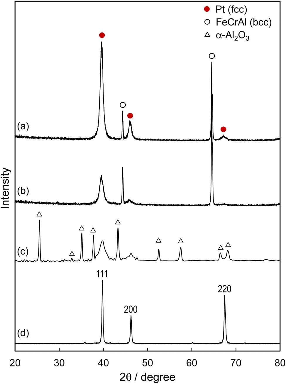 | ||
| Fig. 1 XRD patterns of film catalysts on SUS (Fe–Cr–Al) foil. (a) Pt/p-SUS, (b) Pt/SUS, (c) Pt/Al2O3/SUS and (d) polycrystalline Pt plate. To enhance reflection intensity, Pt was coated onto SUS foils using 8000-shot AP pulses. | ||
The XPS analysis of the Pt/p-SUS and Pt/SUS samples (Fig. S3†) revealed complete coverage of the SUS surfaces by Pt overlayers despite the different surface roughness described below. The amount of deposited Pt was estimated to be approximately 2 nm thick (using 2000-shot AP pulses), assuming deposition onto a completely flat surface. Upon treatment of the SUS foil in the air at 900 °C for 20 h, the Al and O peaks exhibited significant intensification, while the other metal peaks (Fe and Cr) disappeared. Following subsequent AP deposition of Pt, all Al peaks disappeared, concomitant with the appearance of Pt peaks, indicating almost complete surface coverage by Pt regardless of the presence of an Al oxide layer on the foil surface (Pt/Al2O3/SUS). Thus, complete surface coverage by the Pt overlayer was achieved for all these metal foil catalysts.
Fig. 2 presents SEM images illustrating the surface characteristics of these metal foil catalysts. The mirror-polished Pt/p-SUS sample (a) displayed a notably smooth surface compared to the unpolished Pt/SUS sample (b). Conversely, Pt/Al2O3/SUS (c) exhibited a significantly higher degree of surface roughness owing to the rod-like texture of α-Al2O3 deposits, measuring approximately 0.2 μm thick and 0.5–1 μm long. The texture of the Pt overlayer was not discernible in the SEM images owing to its small size, falling below the resolution limit. Quantitative surface roughness analyses were conducted using a 3D laser scanning confocal microscope, as depicted at the bottom of Fig. 2. Compared to the polished Pt/p-SUS sample (a) with an average surface roughness (Ra) of only 8 nm, the Pt/SUS sample (b) exhibited a larger Ra of approximately 94 nm owing to contoured deformation texture formed during the manufacturing rolling process of the SUS foil. On the Pt/Al2O3/SUS sample (c), the Ra value significantly increased to 179 nm. The surface area ratio (Sdr), defined as the increment of the total surface area relative to the flat sampling area (213 × 300 μm), was determined through topographic analysis. The Sdr increased from 0.0001 (a) to 0.011 (b), then to 0.607 (c), indicating an active Pt surface area ratio of 1.000:1.011:1.607. Consequently, the roughness of the surface Al2O3 layer formed by heat treatment in the air (c) is inferred to provide a larger number of active sites than the extremely smooth surface of Pt/p-SUS (a).
 | ||
| Fig. 2 SEM and 3D laser scanning confocal microscope images of the surfaces of (a) Pt/p-SUS, (b) Pt/SUS, and (c) Pt/Al2O3/SUS. Insets in the upper images depict the overall foil samples sized 30 × 30 mm2. Ra and Sdr values (insets of the bottom images) denote surface roughness and surface area ratio, respectively. Pt was deposited onto SUS foils using 2000-shot AP pulses. | ||
The surface topographic analysis highlighted the Pt overlayer's contrasting roughness between the Pt/p-SUS and Pt/Al2O3/SUS samples. For a more comprehensive structural assessment of these Pt overlayer catalysts, the cross-sectional view near the surface of the Pt overlayer was examined through STEM and X-ray mapping analyses. In the case of the Pt/p-SUS sample, the thickness of the Pt overlayer was increased (using 8000-shot AP pulses) to enhance visibility. As depicted in Fig. 3a, Pt/p-SUS exhibited an exceptionally flat and smooth surface with nanometre-level precision. The Pt overlayer displayed continuous growth along the SUS surface, establishing intimate contact. An enlarged image (Fig. 3b) and X-ray mapping images (Fig. 3c) revealed the absence of grain boundaries in the 6 nm-thick Pt overlayer. However, the Pt and SUS foil detected a 2 nm-thick corrosion layer containing Al, Cr and O. This layer likely formed during the mirror polishing process before the AP deposition of Pt overlayers. The Pt overlayer exhibited intimate contact with the corrosion layer, with a clear interface devoid of diffusion of each constituent atom.
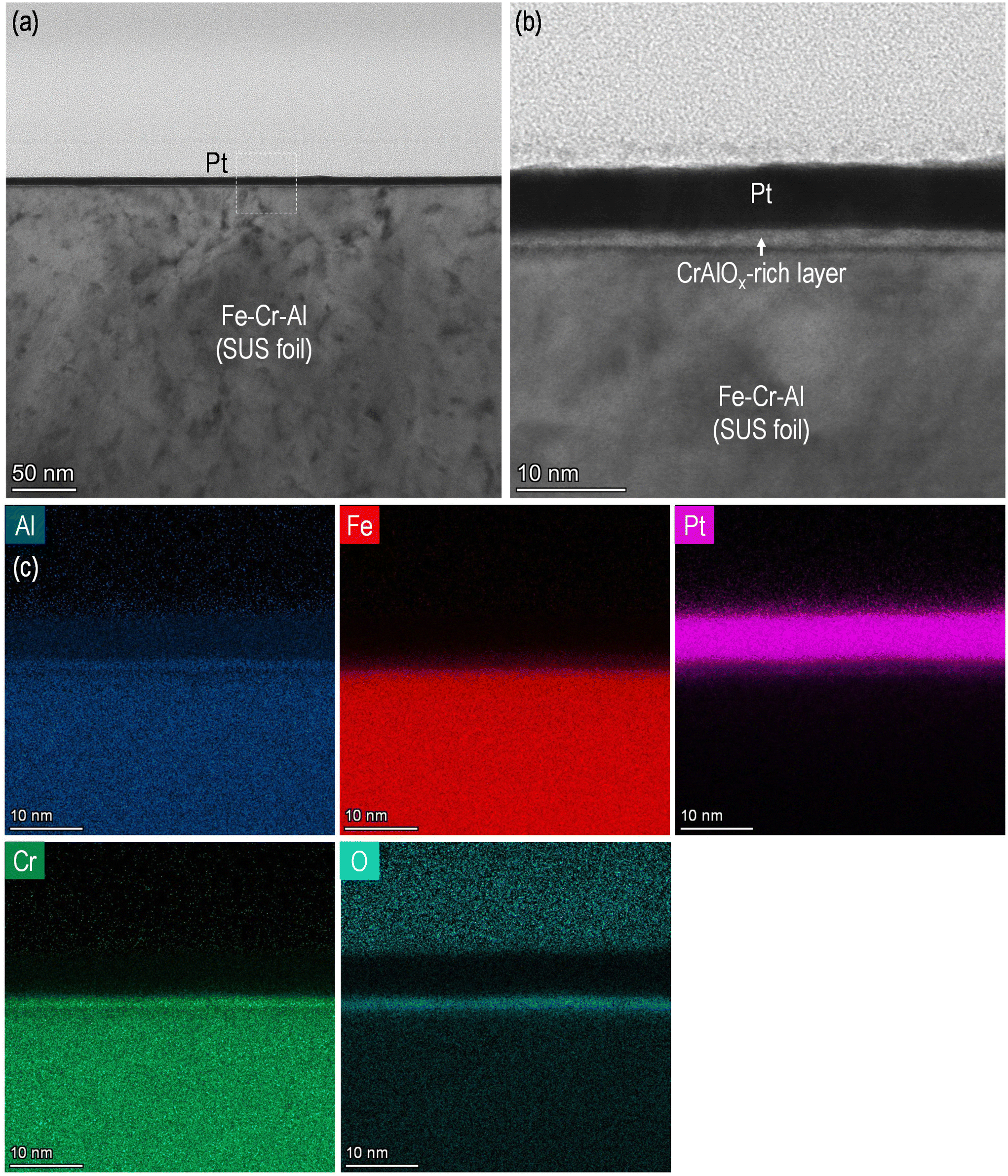 | ||
| Fig. 3 (a) STEM image of the cross-sectional Pt overlayer structure formed on the p-SUS foil. (b) An enlarged image was obtained from a dashed square region of (a). (c) X-ray images obtained from a square region of (a). Pt was deposited onto the SUS foil using 8000-shot AP pulses to enhance visibility. | ||
The cross-sectional images of the Pt overlayer structure formed on the Al2O3/SUS foil are depicted in Fig. 4. In stark contrast to Pt/p-SUS (Fig. 3), the surface of Pt/Al2O3/SUS exhibited significant roughness and undulations. The inner α-Al2O3 layer in contact with the metal foil had a thickness of approximately 1.0–1.4 μm and a surface roughness of a few hundred nanometres (Fig. 4a). X-ray elemental mapping analysis revealed that this layer contained Al and O but not Fe and Cr (Fig. S4†), consistent with forming a dense and adherent α-Al2O3 layer during thermal treatment at 900 °C in air. This surface passivation layer protects the metal foil from further oxidation, ensuring high-temperature stability.38 The dashed square region in the upper right part of Fig. 4a was magnified and analysed by EDS (Fig. 4b–d). The outermost surface of the Al2O3 layer was entirely covered by a layer of Pt nanoparticles a few nanometres thick, formed by pulsed AP deposition, in agreement with the XPS analysis results as described earlier. Notably, the Pt overlayer did not form a continuous coating film but exhibited a stone-wall-like nanotexture comprising closely packed nanometre-sized Pt particles. The overlayer structure displayed no gap beneath the Pt layer, ensuring intimate and strong contact with the Al2O3 layer. The stone-wall structure, arising from the surface roughness of the Al2O3 layer, provided a larger Pt surface area compared to Pt/p-SUS, as illustrated in Fig. 2, thereby enhancing catalytic performance. However, interestingly, this expectation was not fully realised, as detailed in the following section.
 | ||
| Fig. 4 (a) STEM image of the cross-sectional Pt overlayer structure formed on the Al2O3/SUS foil. (b) An enlarged image was obtained from a dashed square region of (a). (c) Al and (d) Pt X-ray images obtained from a square region of (a). Pt was deposited onto the Al2O3/SUS foil using 8000-shot AP pulses to enhance visibility. | ||
3.2. Catalytic NH3 oxidation and turnover frequency (TOF)
Catalytic NH3 oxidation was performed using strips (3 × 30 mm2) of the as-prepared Pt/p-SUS, Pt/SUS, and Pt/Al2O3/SUS samples. When subjected to 2000-shot AP pulsed irradiation on one side only, all three samples received the same amount of Pt deposition. However, their Pt surface areas differed based on surface roughness, increasing in the following order: Pt/p-SUS < Pt/SUS < Pt/Al2O3/SUS, as evidenced by surface topographic analysis (Fig. 2). The temperature dependency of NH3 conversion and product yields is illustrated in Fig. 5. All catalysts exhibited a sharp decline in NH3 concentration starting at temperatures ≥200 °C, accompanied by the formation of N2O and N2. Subsequently, with further temperature increase, N2O/N2 formation tended to decrease, while the formation of NO/NO2 commenced at temperatures ≥250 °C. Particularly noteworthy was the significant difference in catalytic activity at the lowest temperature near 200 °C, where the Pt/p-SUS sample (Fig. 5a) demonstrated notably higher NH3 conversion and N2 yield values despite having the smallest Pt surface area owing to its smooth surface. Conversely, Pt/SUS and Pt/Al2O3/SUS exhibited lower activities at this temperature (b, c). | ||
| Fig. 5 Temperature dependence of NH3 oxidation and product selectivity over a strip (3 × 30 mm2) of (a) Pt/p-SUS, (b) Pt/SUS and (c) Pt/Al2O3/SUS. Pt was deposited using 2000-shot AP pulses on one side of SUS foils. Gas feed composition: 300 ppm NH3, 8% O2, 10% H2O, and He balance, 100 mL min−1. | ||
The TOF for NH3 conversion at 200 °C was calculated (Table 1). Owing to the exceptionally high NH3 conversion over Pt/p-SUS (>60%, Fig. 5a) at 200 °C, a smaller strip size (3 × 10 mm2) was utilised to determine TOF. The number of surface Pt sites was calculated using the geometric area of the foils, Pt surface coverage, Sdr and the surface atomic density of Pt. For Pt/Al2O3/SUS, the surface Pt site was also quantified using the amount of CO uptake. Details of the TOF calculation are outlined in Table S1.† As displayed in Table 1, TOF exhibited a significant increase in the order Pt/Al2O3/SUS < Pt/SUS < Pt/p-SUS, contrary to the order of the Pt surface area described earlier. TOF for Pt/p-SUS (267 min−1) surpassed that of Pt/SUS (107 min−1) by over 2-fold and exceeded that of Pt/Al2O3/SUS (≤22 min−1) by more than 10-fold. Hence, the smoothest Pt overlayer achieved the highest TOF for NH3 oxidation, indicating a negative effect of Pt overlayer roughness on TOF. Previously, our study reported a TOF of approximately 52 min−1 for Pt/SUS, which was over 180-fold greater than that of the reference Pt/Al2O3 powder catalyst (0.28 min−1) containing Pt nanoparticles with an average size of approximately 3 nm.4 Consequently, the Pt/Al2O3/SUS in this study displayed an intermediate TOF value between those of Pt/SUS and Pt/Al2O3. As depicted in Fig. 5, NH3 conversions and product yields over the three metal foil catalysts were nearly comparable at temperatures equal to or higher than 225 °C. On Pt/p-SUS, N2 predominantly formed at 200 °C but gradually decreased with increasing temperature. Conversely, Pt/SUS and Pt/Al2O3/SUS exhibited a steeper decline in N2 yield at elevated temperatures. Thus, the smooth Pt overlayer appears beneficial for accelerating NH3 oxidation and enhancing N2 selectivity.
| Catalyst (strip size) | Pt surface areaa (m2) | Surface Pt (μmol) | NH3 conv.d (%) | Reaction rate (μmol min−1) | TOFe (min−1) |
|---|---|---|---|---|---|
| a Determined by a confocal laser scanning microscope. b Determined by the geometric area of the foil surface, surface coverage (100%), Sdr, and average surface atomic density of Pt (1.54 × 10¹⁹ atom per m2). c Determined by the CO chemisorbed at 50 °C assuming the stoichiometry of CO/Pt = 1. d NH3 conversion at 200 °C (300 ppm NH3, 8% O2, 10% H2O, and a He balance, 100 mL min−1). e Turnover frequency of the NH3 conversion at 200 °C. | |||||
| Pt/p-SUS (3 × 10 mm2) | 3.0 × 10⁻⁵ | 7.67 × 10⁻⁴b |
15.3 | 0.205 | 267 |
| Pt/SUS (3 × 30 mm2) | 9.1 × 10⁻⁵ | 2.33 × 10⁻³b |
18.7 | 0.250 | 107 |
| Pt/Al2O3/SUS (3 × 30 mm2) | 14.4 × 10⁻⁵ | 3.69 × 10⁻³b |
6.2 | 0.083 | 22 |
| — | 1.12 × 10⁻²c |
6.2 | 0.083 | 7 | |
Pt/p-SUS exhibited a notably higher TOF than Pt/SUS and Pt/Al2O3/SUS. The underlying reason for this discrepancy in TOF remains unclear; however, this ranking aligns with the order of surface roughness depicted in Fig. 2. To obtain more information about the reaction mechanism, partial orders concerning NH3, O2 and H2O partial pressures for the conversion rates of NH3 were determined (Table 2 and Fig. S5†). Pt/p-SUS displayed a positive reaction order for NH3 (1.01) but negative orders for both O2 (−0.35) and H2O (−0.39). This observation can be rationalised by assuming that the Pt surface site is predominantly occupied by adsorbed O2 and H2O owing to their abundance in the gas phase. Similar outcomes were observed for unpolished Pt/SUS, although Pt/Al2O3/SUS exhibited a more negative order for O2 (−0.67). Consequently, the lower TOF over Pt/Al2O3/SUS could be attributed to the more dominant adsorption of O2 onto the surface Pt site. These partial orders are characteristic of the present reaction condition in an excess O2 and the result will be different under NH3-rich conditions, where the Pt surface is primarily covered with nitrogen-containing species.
The Pt oxidation state of these samples was examined via XPS analysis (Fig. 6). Despite the surface roughness, the Pt 4d spectra showed that the fraction of metallic Pt was only slightly higher in Pt/p-SUS and Pt/SUS (Pt0/Pt ∼ 92%) compared to Pt/Al2O3/SUS (Pt0/Pt < 90%). These fractions were kept almost unchanged even after use in the catalytic test at ≤300 °C. It is widely acknowledged that metallic Pt is more active than oxidised Pt for the dissociation of adsorbed O2 molecules.13,39 A more noticeable contrast was observed in the O 1s spectra; notably, the Pt/p-SUS sample exhibited a significantly lower O 1s peak than Pt/SUS and Pt/Al2O3/SUS. The peak was very broad in the range of binding energy 530–534 eV, and thus contained different components. Based on the literature assignment,40–45 the peak could be partitioned into contributions from Pt oxide, adsorbed oxygen and H2O, although the contribution from oxide was small because the Pt surface was mostly in a metallic state. Assuming this peak is attributed to adsorbed oxygen species,46,47 this finding suggests that the stability of adsorbed oxygen on Pt/p-SUS is considerably lower than that on the other samples. Such situations may explain the smaller negative order in O2 for Pt/p-SUS relative to Pt/Al2O3/SUS (Table 2). Previous surface science studies have indicated that NH3 oxidation on Pt is initiated by forming reactive intermediate NHx species through N–H bond cleavage, with atomic oxygen provided by adsorbed O2 playing a pivotal role.13,16,19,48 The adsorbed oxygen is bound weakly on terrace sites but strongly on edge sites.32,49 Furthermore, the nature of the adsorbed oxygen species may vary from atomic (on terrace sites) to ionic (on edge sites).50 Based on the hypothesis and O 1s XPS results (Fig. 6), strongly bound oxygen species are believed to be less abundant on Pt/p-SUS than on Pt/Al2O3/SUS, thus affecting the catalytic activity. Considering that the Pt overlayer samples contain structural varieties (terraces, steps, kinks, and other defects), it seems difficult to discuss the reactivity of these different oxygen species toward NH3. Nonetheless, the present kinetic studies indicated that the NH3 oxidation rate showed a more positive order in NH3 pressure but showed a less negative order in O2 pressure over Pt/p-SUS compared to Pt/Al2O3/SUS. The result implies that the nanometric smoothness of the Pt surface is favored for the facile adsorption and activation of NH3 in excess oxygen. The surface reaction between NHx and atomic oxygen results in a higher concentration of nitrogen atoms, leading to the formation of N2 through the combination of two adsorbed nitrogens. This provides a plausible explanation for the observed higher N2 selectivity in Pt/p-SUS.
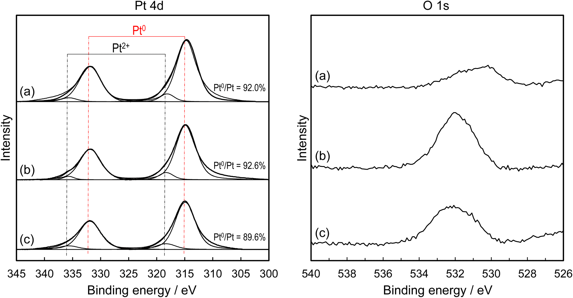 | ||
| Fig. 6 Pt 4d and O 1s XPS spectra of (a) Pt/p-SUS, (b) Pt/SUS and (c) Pt/Al2O3/SUS (2000 shot AP pulses). The peak intensity is normalised by Pt 4f peaks because the Pt overlayer fully covered the surface of the metal foil catalysts. | ||
4. Conclusions
In this study, we utilised a pulsed cathodic arc–plasma deposition method to fabricate a nanometric Pt overlayer on 50 μm-thick SUS foil substrates featuring varying degrees of surface roughness, i.e., p-SUS, SUS and Al2O3/SUS. We assessed the surface roughness quantitatively and qualitatively through comprehensive analysis employing SEM, STEM-EDS, laser scanning confocal microscopy and chemisorption techniques. Notably, the surface roughness (Ra) exhibited a descending trend, with Pt/Al2O3/SUS (179 nm) demonstrating the highest value, followed by Pt/SUS (94 nm) and then Pt/p-SUS (8 nm). Consequently, the surface area ratio (Sdr) and the number of active sites declined correspondingly in this order. However, despite these trends, the NH3 oxidation activity measured at 200 °C exhibited the opposite order. Specifically, the calculated TOF was most pronounced for Pt/p-SUS (267 min−1), followed by Pt/SUS (107 min−1) and Pt/Al2O3/SUS (≤22 min−1). This unexpected result underscores the sensitivity of high-TOF NH3 oxidation over Pt overlayer catalysts to their nanometric surface roughness. Moreover, we observed that the surface smoothness of the Pt overlayer conferred benefits in terms of yielding N2 over an undesirable byproduct (N2O).Data availability
The data supporting this study's findings are available from the corresponding author upon reasonable request.Author contributions
M. Machida proposed, planned the research and wrote the manuscript. N. Yamasaki, T. Miyoshi and H. Kusaba performed the sample preparation and catalytic reactions, and analyzed the data under the supervision of M. Machida. K. Awaya, H. Yoshida, J. Ohyama and T. Sato performed characterisation. T. Ohori, K. Oka, K. Fujii and N. Ishikawa performed electron microscopic characterisation. The manuscript was written with input from all authors, and all authors have approved the final version.Conflicts of interest
The authors declare no conflict of interest.Acknowledgements
This work was financially supported by JSPS KAKENHI (Grant Number 22H00277). The authors thank the Kanagawa Institute of Industrial Science and Technology for cooperation in the FIB and STEM experiments.References
- S. Misumi, H. Yoshida, S. Hinokuma, T. Sato and M. Machida, Sci. Rep., 2016, 6, 29737 CrossRef CAS PubMed
.
- H. Yoshida, K. Koizumi, M. Boero, M. Ehara, S. Misumi, A. Matsumoto, Y. Kuzuhara, T. Sato, J. Ohyama and M. Machida, J. Phys. Chem. C, 2019, 123, 6080–6089 CrossRef CAS
- H. Yoshida, S. Misumi, A. Matsumoto, Y. Kuzuhara, T. Sato, J. Ohyama and M. Machida, Catal. Sci. Technol., 2019, 9, 2111–2117 RSC
- M. Machida, Y. Tokudome, A. Maeda, Y. Kuzuhara, T. Hirakawa, T. Sato, H. Yoshida, J. Ohyama, K. Fujii and N. Ishikawa, ACS Catal., 2020, 10, 4677–4685 CrossRef CAS
- M. Machida, Y. Tokudome, A. Maeda, T. Koide, T. Hirakawa, T. Sato, M. Tsushida, H. Yoshida, J. Ohyama, K. Fujii and N. Ishikawa, ACS Omega, 2020, 5, 32814–32822 CrossRef CAS PubMed
- M. Machida, Y. Tokudome, A. Maeda, T. Sato, H. Yoshida, J. Ohyama, K. Fujii and N. Ishikawa, Catal. Today, 2022, 384–386, 70–75 CrossRef CAS
- H. Yoshida and M. Machida, ChemCatChem, 2023, 15, e202300771 CrossRef CAS
- M. Machida and H. Yoshida, Mater. Trans. JIM, 2023, 64, 2369–2375 CrossRef CAS
- J. Zhou, B. Guan, J. Guo, C. Zheng, T. Su, J. Chen, Y. Zhang, Y. Yuan, H. Dang, Y. He, Z. Wei, B. Xu, C. Xu, C. Yi, W. Zeng and Z. Huang, Ind. Eng. Chem. Res., 2023, 62, 20506–20546 CrossRef CAS
- T. Lan, Y. Zhao, J. Deng, J. Zhang, L. Shi and D. Zhang, Catal. Sci. Technol., 2020, 10, 5792–5810 RSC
- L. Chmielarz and M. Jabłońska, RSC Adv., 2015, 5, 43408–43431 RSC
- F. Gao, Y. Liu, Z. Sani, X. Tang, H. Yi, S. Zhao, Q. Yu and Y. Zhou, J. Environ. Chem. Eng., 2021, 9, 104575 CrossRef CAS
- W. D. Mieher and W. Ho, Surf. Sci., 1995, 322, 151–167 CrossRef CAS
- Y. Li and J. N. Armor, Appl. Catal., B, 1997, 13, 131–139 CrossRef CAS
- A. C. M. van den Broek, J. van Grondelle and R. A. van Santen, J. Catal., 1999, 185, 297–306 CrossRef CAS
- J. Pérez-Ramírez, E. V. Kondratenko, V. A. Kondratenko and M. Baerns, J. Catal., 2004, 227, 90–100 CrossRef
- C. J. Weststrate, J. W. Bakker, A. C. Gluhoi, W. Ludwig and B. E. Nieuwenhuys, Catal. Today, 2010, 154, 46–52 CrossRef CAS
- S. Hinokuma, H. Shimanoe, S. Matsuki, M. Kawano, Y. Kawabata and M. Machida, Chem. Lett., 2016, 45, 179–181 CrossRef CAS
- H. Ma and W. F. Schneider, ACS Catal., 2019, 9, 2407–2414 CrossRef CAS
- D. A. Svintsitskiy, L. S. Kibis, A. I. Stadnichenko, E. M. Slavinskaya, A. V. Romanenko, E. A. Fedorova, O. A. Stonkus, D. E. Doronkin, V. Marchuk, A. Zimina, M. Casapu, J.-D. Grunwaldt and A. I. Boronin, ChemCatChem, 2020, 12, 867–880 CrossRef CAS
- E. M. Slavinskaya, L. S. Kibis, O. A. Stonkus, D. A. Svintsitskiy, A. I. Stadnichenko, E. A. Fedorova, A. V. Romanenko, V. Marchuk, D. E. Doronkin and A. I. Boronin, ChemCatChem, 2021, 13, 313–327 CrossRef CAS
- C. Fukuhara, R. Hyodo, K. Yamamoto, K. Masuda and R. Watanabe, Appl. Catal., A, 2013, 468, 18–25 CrossRef CAS
- C. Xu, X. Zhang and Z. Yang, J. Phys.: Condens. Matter, 2020, 32, 175201 CrossRef CAS PubMed
- K. Hayashi, S. Kameoka and A.-P. Tsai, Mater. Trans. JIM, 2021, 62, 1089–1096 CrossRef CAS
- R. A. Van Santen, Acc. Chem. Res., 2009, 42, 57–66 CrossRef CAS PubMed
- C. H. F. Peden, D. N. Belton and S. J. Schmieg, J. Catal., 1995, 155, 204–218 CrossRef CAS
- G. C. Bond, Acc. Chem. Res., 1993, 26, 490–495 CrossRef CAS
- Y. F. Zeng and R. Imbihl, J. Catal., 2009, 261, 129–136 CrossRef CAS
- K. Yang and B. Yang, Appl. Surf. Sci., 2022, 584, 152584 CrossRef CAS
- J. L. Gland and V. N. Korchak, J. Catal., 1978, 53, 9–23 CrossRef CAS
- E. Xue, K. Seshan and J. R. H. Ross, Appl. Catal., B, 1996, 11, 65–79 CrossRef CAS
- L. M. Carballo and E. E. Wolf, J. Catal., 1978, 53, 366–373 CrossRef CAS
- M. C. Demicheli, L. C. Hoang, J. C. Ménézo, J. Barbier and M. Pinabiau-Carlier, Appl. Catal., A, 1993, 97, L11–L17 CrossRef CAS
- T. F. Garetto and C. R. Apesteguía, Appl. Catal., B, 2001, 32, 83–94 CrossRef CAS
- T. F. Garetto and C. R. Apesteguía, Catal. Today, 2000, 62, 189–199 CrossRef CAS
- H. Lieske, G. Lietz, H. Spindler and J. Völter, J. Catal., 1983, 81, 8–16 CrossRef CAS
- A. Borgna, F. Le Normand, T. Garetto, C. R. Apesteguia and B. Moraweck, Catal. Lett., 1992, 13, 175–188 CrossRef CAS
-
R. M. Heck, R. J. Farrauto and S. T. Gulati, Catalytic Air Pollution Control: Commercial Technology, Wiley, Hoboken, 1995 Search PubMed
- D. P. Sobczyk, E. J. M. Hensen, A. M. de Jong and R. A. van Santen, Top. Catal., 2003, 23, 109–117 CrossRef CAS
- N. Materer, U. Starke, A. Barbieri, R. Döll, K. Heinz, M. A. Van Hove and G. A. Somorjai, Surf. Sci., 1995, 325, 207–222 CrossRef CAS
- J. F. Zhu, M. Kinne, T. Fuhrmann, B. Tränkenschuh, R. Denecke and H. P. Steinrück, Surf. Sci., 2003, 547, 410–420 CrossRef CAS
- A. C. Luntz, J. Grimblot and D. E. Fowler, Phys. Rev. B: Condens. Matter Mater. Phys., 1989, 39, 12903–12906 CrossRef CAS PubMed
- C. Puglia, A. Nilsson, B. Hernnäs, O. Karis, P. Bennich and N. Mårtensson, Surf. Sci., 1995, 342, 119–133 CrossRef CAS
- M. Peuckert and H. P. Bonzel, Surf. Sci., 1984, 145, 239–259 CrossRef CAS
- W. Ranke and H. J. Kuhr, Phys. Rev. B: Condens. Matter Mater. Phys., 1989, 39, 1595–1601 CrossRef CAS PubMed
- C. J. Weststrate, J. W. Bakker, E. D. L. Rienks, C. P. Vinod, A. V. Matveev, V. V. Gorodetskii and B. E. Nieuwenhuys, J. Catal., 2006, 242, 184–194 CrossRef CAS
- J. L. G. Fierro, J. M. Palacios and F. Tomas, Surf. Interface Anal., 1988, 13, 25–32 CrossRef CAS
- G. Novell-Leruth, J. M. Ricart and J. Pérez-Ramírez, J. Phys. Chem. C, 2008, 112, 13554–13562 CrossRef CAS
- H. Wang, R. G. Tobin, D. K. Lambert, C. L. DiMaggio and G. B. Fisher, Surf. Sci., 1997, 372, 267–278 CrossRef CAS
- A. R. Vaccaro, G. Mul, J. Pérez-Ramírez and J. A. Moulijn, Appl. Catal., B, 2003, 46, 687–702 CrossRef CAS
Footnote |
| † Electronic supplementary information (ESI) available. See DOI: https://doi.org/10.1039/d4nr01156b |
| This journal is © The Royal Society of Chemistry 2024 |