 Open Access Article
Creative Commons Attribution 3.0 Unported Licence
Additively manufactured customized microhelix motors' bursting motion in mesoscopic tubes for vessel declogging†
Yang Cao‡
ab,
Hongyu Yi‡ab,
Kongyu Ge‡ab,
Yifan Gaoab,
Zhenchao Zhangab and
Huanhuan Feng *ab
*ab
aSauvage Laboratory for Smart Materials, Shenzhen Key Laboratory of Flexible Printed Electronics Technology, Harbin Institute of Technology (Shenzhen), China. E-mail: fenghuanhuan@hit.edu.cn; Tel: +86755-86148426
bState Key Laboratory of Advanced Welding and Joining (Shenzhen), Harbin Institute of Technology (Shenzhen), China
First published on 16th January 2024
Abstract
Magnetic microhelix motors are widely employed in various applications such as cargo transportation, drug delivery, toxic substance declogging, and cell manipulation, due to their unique adaptive magnetic manipulation capabilities. In this work, high-precision stereoscopic additive manufacturing techniques were used to produce customized microhelices with varying structural parameters, including different pitch numbers (2–4 pitches), sizes (0.1–0.25 mm), and taper angles (172°–180°). Their motion performance in mesoscopic tubes was systematically investigated. The magnetic microhelix motors' speed increases when circle numbers and taper angles decrease, while circle diameters increase. The magnetic microhelix motors' speed could achieve a 1500% enhancement reaching 0.16 mm s−1 in a 0.3 mm tube, with a pitch number of 3, diameter of 0.2 mm, and taper angle of 172°. Furthermore, their vessel declogging capability is confirmed in in vitro experiments.
Introduction
Microhelix motors are fascinating artificial tinny machines.1–11 They are capable of autonomous motion-powered tasks,12–15 such as target drug delivery,16,17 microsurgery,18,19 biosensing,20–22 and contaminant degradation.23,24 In general, motors based on varying materials and structures gain thrust from either chemical reactions or external fields. Chemical-driven motors transfer the chemical energy stored in fuels to driven power, but chemical reactions are easily affected by complex chemical environments in the human body, thereby reducing stability.25 Magnetic propulsion is another common way for micromotor movement. By featuring micromotor magnetism, they can be easily manipulated through different applied magnetic fields, without interacting with surroundings. This guarantees their great stability and accuracy. Therefore, magnetic micromotors have been widely studied in recent years.26,27The fabrication of magnetic microhelix motors is based on the most advanced materials science and engineering technology and combined with multidisciplinary knowledge (bioengineering, computer science, mechanical engineering).27–33 Four fabrication methods are mainly employed to make micro and nano helical structures, namely rolled-up, GLAD (Glancing Angle Deposition), DLW (Direct Laser Writing), and TA (Template-Assisted).34–40 Huang's team used the Rolled-up method to fabricate reconfigurable micro-origami motors.41 This method is the most convenient way for the mass production of micromotors and is capable of fabricating motors with any inorganic materials.42 However, it can merely fabricate tubular motors, which limits the motor geometry. DLW is a powerful method allowing the fabrication of designable and complex nano-scale structures with high resolution.43 This technique is quite flexible, but the complex procedures result in high costs and hinder the mass-production. GLAD is a useful tool for nanofabrication, which can deposit any type of structure with almost no material limit.44,45 Fischer's team fabricated one of the smallest magnetically driven nano screws with a diameter of 70 nm using the GLAD method.46 While GLAD has proved to be a very promising technique for nanostructure fabrication, the exclusive machines and complex procedures are still crucial challenges to be solved. Template-based methods are low-cost, convenient ways to fabricate versatile micromotors, but they are not sophisticated enough to control the growth orientations.47
Additive manufacturing (or 3D printing) has been proven to be a promising nanofabrication method in recent years.48 The designed 3D objects are realized by adding materials layer by layer, which minimizes waste. Projection micro stereolitho-graphy is a new additive manufacturing method based on ultraviolet light polymerization. The 3D model will be sliced into several 2D patterns in advance, and the shaped ultraviolet light with the corresponding patterns will be focused on the prepolymer. Each exposure will be able to fabricate one layer of the object, which enables high-precision, low-cost, and convenient nanofabrication.49
This work successfully fabricates microhelix motors with different structures using a high-precision additive manufacturing device, BMF S130. It can create complex 3D objects with exceptional precision, down to 2 μm, by layering materials to construct designed structures. Its capability provides a powerful toolset for systematic additive manufacturing of microhelices. The fabrication process is shown in Fig. 1a and b. The magnetic response can be featured via sputtering Ni, and the magnetic pole distribution is oriented longitudinally along the rotational axis of the microhelices. Microhelix can be axially rotated under the magnetic field and the microhelix motors can be easily manipulated for different functions, rendering it an ideal candidate for simulating in vitro embolus declogging.
 | ||
| Fig. 1 Schematic diagram of magnetic microhelix motor fabrication and declogging experiment. (a) Additive manufacture. (b) Ni sputtering. (c) Polarity distribution. (d) Moving performance tests. | ||
Materials and methods
Materials
Demi-water, anhydrous ethanol, sodium dodecyl sulfate (Macklin's), HTL-type light-curing resin (Shenzhen BMF Co., Ltd), and other chemicals are primarily used during the experimental operation. A 0.9% concentration saline solution is used in the investigation of the motion law of the magnetic microhelix motor.Microhelix motor fabrication
High-precision stereoscopic additive manufacturing is achieved using a BMF S130 printer, which has an additive manufacturing accuracy of 2 microns, a maximum format of 50 mm (L) * 50 mm (W), and a print layer thickness of 5 μm. The printing solution is HTL-type light-curing resin. Motors with different parameters are designed using SolidWorks 3D modeling software. These models are sliced into layers with a thickness of 5 μm each. The sliced data is then imported into the 3D printer. The UV light intensity is set at 70 mW cm−2, and each layer's leveling time ranges from 90 seconds to 150 seconds. Additionally, a scraper moves from left to right to remove any bubbles every 6 layers, preventing possible negative effects.Magnetism featuring
Magnetic response is featured via sputtering Ni. A vacuum nickel-plating machine is the primary instrument used to confer magnetism to the microhelix. The sputtering parameters are as follows: the atmospheric pressure is 4 × 10⁻⁴ Pa, the sputtering rate is around 0.3 Å s−1, and the thickness is around 600 Å when the sputtering time is 30 minutes.Magnetic field preparation and driven
The magnetic field is created by a three-dimensional magnetic control device consisting of Helmholtz coils and Maxwell coils. Maxwell coils generate a gradient field, while Helmholtz coils generate a uniform magnetic field, thereby allowing for the translational motion in all directions of microhelix motors.Results
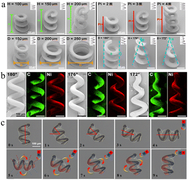
Scanning electron microscopy (SEM) is employed to validate the morphological and structural precision of the printed microhelices. The surface projection micro-stereolithography S130 system permits full customization of microhelix parameters at the micron scale, achieving an exceptional processing precision of up to 10 μm, as shown in Fig. 2a. This enables meticulous adjustment of distinct structural parameters and the control of dimensional error within a 10 μm margin.Parameters such as microhelix height (H), pitch number (Pi), bottom circle diameter (d), and taper angle (θ) are investigated to optimize its moving and declogging capabilities. Microhelices with diverse parameters are manufactured, including height from 0.1 mm to 0.2 mm, pitch numbers from 2 to 4, bottom circle diameters from 0.1 mm to 0.2 mm, and taper angles varying between 180° and 172°. These microhelices are characterized in Fig. 2a.
To confer magnetic properties on those microhelices, a surface-sputtering process with nickel is employed. Microhelices characterized by taper angles of 180°, 176°, and 172° are chosen for Energy Dispersive Spectroscopy (EDS) elemental analysis after the nickel sputtering, as shown in Fig. 2b. In the EDS analysis, carbon is depicted in green, while nickel is depicted in red, indicating the successful deposition of metallic nickel on the microhelix surface.
Subsequently, the polarity distribution of the nickel-coated microhelix motor is investigated using a permanent magnet with a known polarity distribution. The magnet is initially positioned perpendicular to the motor and moves toward it. The motor responds with a 90° clockwise rotation, aligning itself in parallel with the magnet. Furthermore, the motor exhibits synchronized rotation with the permanent magnet when the latter is rotated clockwise. Upon the cessation of the magnet's rotation, the motor also comes to a stop, maintaining its parallel alignment with the magnet, as shown in Fig. 2c. These observations suggest that the microhelix motor possesses a transverse polarity distribution, consistent with the polarity distribution of the permanent magnet employed in this investigation.
The optimization of microhelix motors is realized through the manipulation of key parameters, including pitch number (Pi), motor diameter (d), tube diameter (D), and taper angle (θ). Comparative speed experiments are conducted for magnetic microhelix motors in both constrained and non-constrained environments. These motors are principally propelled by a three-dimensional magnetic field, which is generated by Maxwell and Helmholtz coils. Therefore, they can attain planar rotational forward motion under controlled conditions.
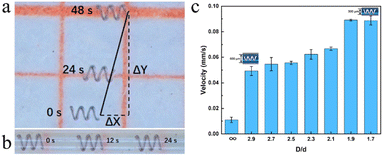
Microhelix motors with specific parameters – a pitch number (Pi) of 3, a taper angle (θ) of 180°, and a bottom circle diameter (d) of 0.2 mm – are chosen for the investigation of their performance under a controlled Helmholtz magnetic field frequency of 10 Hz. The motion speeds are recorded in both non-constrained and constrained areas, as detailed in Fig. 3 and Table 1. The speed of the microhelix motor in the constrained area exceeds that in the non-constrained area by a factor of 4. The details are shown in videos S1 and S2.†
| Direction of motion | Displacement (mm) | Average speed (mm s−1) | ||
|---|---|---|---|---|
| NC | C | Non-constrained environment | Constrained environment | |
| Y-direction | 1.9 | 0 | 0.079 | 0 |
| X-direction | 0.5 | 2 | 0.021 | 0.083 |
To investigate the influence of the diameter of tubes, mesoscopic tubes ranging from 0.3 mm to 0.6 mm in diameter (D) are fabricated for subsequent experiments. The tubes are filled with a 0.9% saline solution to offset the gravitational effects on the microhelix motor. Microhelix motors are placed inside the mesoscopic tubes with varying diameters under a controlled magnetic field of 10 Hz. Motion analysis is conducted using high-speed, high-definition digital cameras, and forward speed is measured using the picture interception method. The results are shown in Fig. 3c. The microhelix motor's speed displays a positive correlation with the D/d ratio, suggesting that increased confinement within the mesoscopic tube leads to enhanced forward speed by minimizing lateral drift.
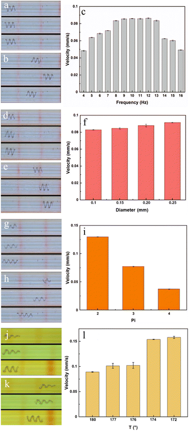
Subsequently, the correlation between the forward motion speed of the microhelix motor and the magnetic field is examined. The frequency of magnetic field alterations plays a crucial role in determining the motor's performance. Thereby, a motor with a 0.2 mm bottom diameter, 3 pitches, and a 180° taper angle is selected and placed inside a rigid glass tube with a 0.3 mm inner diameter for frequency experiments. The motor is subjected to varying magnetic field frequencies, and the swimming velocity is recorded, as shown in Fig. 4a–c and video S3.† When the magnetic field frequency is set to 9, 10, 11, or 12 Hz, the velocity of the motor reaches its maximum. This is because a low-frequency magnetic field provides insufficient energy for motor movement, while motors cannot keep up with a magnetic field of high frequency. Therefore, a frequency of 10 Hz is selected for the following tests.
Motors with different parameters are fabricated to identify the highest velocity. The details are shown in Table 2. Motors in groups 1, 2, 3, and 4 are chosen to investigate the influence of varying bottom diameters. The results are shown in Fig. 4d–f and video S4.† The results show that as the bottom diameter is increased from 0.1 mm to 0.25 mm, the speed is slightly raised from 0.08 mm s−1 to 0.09 mm s−1, representing a 12% enhancement. However, a large bottom diameter may result in motors becoming lodged in veins, impeding their forward movement; and the clogs also may pass through the motor without being effectively pushed. Therefore, motors with diameters of 0.2 mm are selected for the following tests.
| Group | Bottom diameters (mm) | Pitch numbers | Tapers (°) |
|---|---|---|---|
| 1 | 0.1 | 3 | 180 |
| 2 | 0.15 | 3 | 180 |
| 3 | 0.2 | 3 | 180 |
| 4 | 0.25 | 3 | 180 |
| 5 | 0.2 | 2 | 180 |
| 6 | 0.2 | 4 | 180 |
| 7 | 0.2 | 3 | 177 |
| 8 | 0.2 | 3 | 176 |
| 9 | 0.2 | 3 | 174 |
| 10 | 0.2 | 3 | 172 |
Subsequently, motors in groups 3, 5, and 6 are chosen to investigate the influence of different pitch numbers. The results are shown in Fig. 4g–i and video S5.† As the pitch number increases, the motor speed experiences a significant reduction. When the number of motor pitches is reduced from 4 to 2, the motor speed increases from 0.04 mm s−1 to 0.13 mm s−1, representing a 225% enhancement. However, motors with pitch numbers below 3 posed challenges in controlling their direction of movement. Thereby, motors with 3 pitches are chosen for the following tests.
Finally, motors in groups 3, 7, 8, 9, and 10 are chosen to explore the impact of different taper angles. The results are shown in Fig. 4j–l and video S6.† Altering the taper angle from 180° to 172° leads to an increase in motor speed, rising from 0.08 mm s−1 to 0.16 mm s−1, representing a 100% enhancement. Meanwhile, motors with a 172° taper angle demonstrate the ability to prevent clogs from passing through.
Now, we've demonstrated the motor speed could be lifted with a constrained area, moderate magnetic frequency, smaller bottom diameter, fewer pitch numbers, and reduced taper angles. Constrained area limits the motor's lateral moving, fewer pitch numbers reduce the rotary energy the motor needs, and reduced taper angles give the motor smaller viscous force. Fig. 5 summarizes the constrained area and taper angle factors. As the taper angle decreases, the motor speed increases, and the relative increase in speed reaches the greatest at 12°. However, the highest absolute speed of the motor is at 16° with the smallest D/d. Therefore, through the experiments described above, optimal parameters are gained: a bottom diameter of 0.2 mm, a pitch number of 3, and a taper angle of 172°, corresponding to motors from group 10.
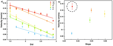 | ||
| Fig. 5 Comparison of tapered magnetic micromotors under constrained areas. (a) Relationship between D/d and the forward speed of the motor with different tapers; (b) optimal values of motor speed. | ||
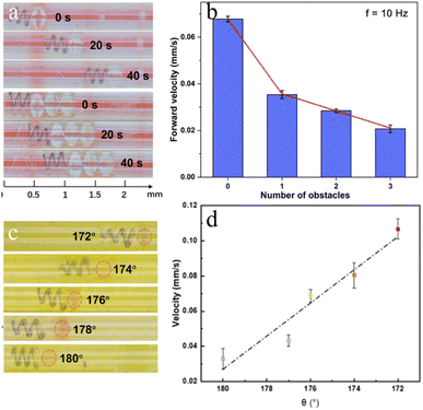
The optimized microhelix motor is subsequently subjected to obstacle-pushing experiments, during which it encounters and pushes varying numbers of polystyrene (PS) balls (0, 1, 2, and 3), each with an approximate diameter of 0.3 mm and a mass of 0.06 g. The experiments are conducted in tubes with a diameter of 0.4 mm, filled with a 0.9% saline solution to offset the gravitational effects on the microhelix motor, as shown in Fig. 6a and video S7.† Motion analysis is conducted using high-speed, high-definition digital cameras, and forward speed is measured using the picture interception method on multiple occasions. The results are illustrated in Fig. 6b. Maintaining a constant mesoscopic tube diameter, we observe a decline in motor speed as the number of PS balls increases. When the number of PS balls reaches three, the speed decreases to approximately 0.02 mm s−1, effectively reaching the magnetic microhelix motor's maximum carrying capacity. These experiments demonstrate the motor's ability to transport rigid obstacles six times its mass at a speed of 0.02 mm s−1.
Subsequently, an arterial vascular embolism push experiment is conducted. In previous experiments, an intriguing phenomenon was observed: motors with taper angles exhibited different speeds during forward and backward motion. The motors exhibit higher speed when the larger end led, achieving an approximately 50% improvement compared to when the smaller end led. Furthermore, when these motors are pushing soft obstructions such as coagulated pig blood, the smaller-end-lead method may make the end lodged in the clog, while the larger-end-lead method allows for a smooth push, as shown in video S8.† Therefore, the larger end is chosen to take the lead during the experiments.
Microhelix motors, featuring optimal performance parameters as determined from prior experimental studies, are chosen and positioned within a simulated blood vessel to facilitate the removal of embolic materials. The mesoscopic tube has a diameter of 0.3 mm. To simulate arterial emboli, semi-solids created from coagulated pig blood are employed, while a 0.9% saline solution is used to replicate the internal environment of blood vessels. The influence of varying taper angles on the declogging process is investigated. Microhelix motors with a bottom diameter of 0.2 mm, featuring 3 pitches and varying tapers are chosen for the experiments. Blood clots are meticulously crafted into irregular shapes, each approximately 0.15 mm in diameter. A mesoscopic tube with a diameter of 0.3 mm is filled with a 0.9% saline solution to mimic the biological internal environment. The microhelix motors and blood clots are placed inside the tube, and the assembly is then positioned on the magnetic control platform. A consistent magnetic field of 10 Hz is applied to drive the magnetic microhelix motor, pushing the clot and simulating the thrombus declogging process. As shown in Fig. 6c and d, the microhelix motor's clot-pushing speed increases from 0.03 mm s−1 to 0.11 mm s−1, representing an approximate 200% increase, as the taper reduces from 180° to 172°. Consequently, the optimized magnetic microhelix motor demonstrates significantly greater efficiency in removing clot material.
Conclusions
Additive manufacturing has been a versatile tool for the fabrication of complex customized microhelix motors. In this work, customized micromotors with adjustable structures are fabricated using an S130 3D printer, and the factors affecting the motors' moving performance are investigated. The motor speed can be lifted with a constrained area, moderate magnetic frequency, smaller bottom diameter, fewer pitch numbers, and reduced taper angles. The motor with a bottom diameter of 0.2 mm, a pitch number of 3, and a taper angle of 172° shows the greatest speed, reaching 0.16 mm s−1 under a constrained area with an applied 10 Hz magnetic field. Our micromotors outperform other motors of the same type and enhance the forward-moving speed 2–3 times (Table 3). The optimized motor is then applied in the in vitro vascular embolism push experiment. The customized motor exhibits great declogging performance for both rigid and soft obstacles.Author contributions
Yang Cao: formal analysis, investigation, writing – original draft. Hongyu Yi: investigation, writing – original draft, review & editing. Kongyu Ge: data curation, writing – review & editing. Zhenchao Zhang: investigation, data curation. Huanhuan Feng: conceptualization, methodology, writing – review & editing, supervision, project administration, funding acquisition.Conflicts of interest
The authors declare no conflict of interest.Acknowledgements
This work was financially supported by the Shenzhen Science and Technology Planning Project (Grant Numbers JCYJ20180507183224565 and ZDSYS20190902093220279) and the Shenzhen Pea-cock Group (Grant Numbers KQTD20170809110344233 and KQTD20200820113045083). The data supporting this study's findings are available from the corresponding author upon reasonable request.Notes and references
- L. Baptista-Pires, J. Orozco, P. Guardia and A. Merkoçi, Small, 2018, 14, 1702746 CrossRef PubMed.
- B. Doshi, M. Sillanpaa and S. Kalliola, Water Res., 2018, 135, 262 CrossRef CAS PubMed.
- W. Gao, X. Feng, A. Pei, Y. Gu, J. Li and J. Wang, Nanoscale, 2013, 5(11), 4696–4700 RSC.
- W. Gao, A. Pei and J. Wang, Acs Nano, 2012, 6, 8432–8438 CrossRef CAS.
- B. Jurado-Sánchez, M. Pacheco, R. Maria-Hormigos and A. Escarpa, Appl. Mater. Today, 2017, 9, 407–418 CrossRef.
- E. Karshalev, B. E.-F. D. Ávila and J. Wang, J. Am. Chem. Soc., 2018, 140, 3810–3820 CrossRef CAS.
- B. Khezri and M. Pumera, Adv. Mater., 2019, 31, 1806530 CrossRef.
- X. Li, F. Mou, J. Guo, Z. Deng, C. Chen, L. Xu, M. Luo and J. Guan, Micromachines, 2018, 9, 23 CrossRef.
- L. Baptista-Pires, J. Orozco, P. Guardia and A. Merkoci, Small, 2018, 14(3), 1702746 CrossRef.
- W. Ma and H. Wang, Appl. Mater. Today, 2019, 15, 263–266 CrossRef.
- B. Jurado-Sánchez and J. Wang, Environ. Sci.: Nano, 2018, 5(7), 1530–1544 RSC.
- D. Schamel, A. G. Mark, J. G. Gibbs, C. Miksch, K. I. Morozov, A. M. Leshansky and P. Fischer, ACS Nano, 2014, 8(9), 8794–8801 CrossRef CAS PubMed.
- K.-C. Fan, R.-J. Li and P. Xu, Nanomanuf. Metrol., 2019, 2, 1–15 CrossRef.
- E. W. Jager, O. Inganas and I. Lundstrom, Science, 2000, 288(5475), 2335–2338 CrossRef CAS PubMed.
- V. Katherine, V. Jan, Y. Yulong, Z. Jaroslav and P. Martin, Chemistry, 2020, 14, 3039–3043 Search PubMed.
- F. Mou, C. Chen, Q. Zhong, Y. Yin, H. Ma and J. Guan, ACS Appl. Mater. Interfaces, 2014, 6, 9897–9903 CrossRef CAS PubMed.
- F. Qin, Y. Zhang and F. Peng, ChemNanoMat, 2021, 7(4), 415–428 CrossRef CAS.
- A. C. Tsang, E. Demir, Y. Ding and O. S. Pak, Adv. Intell. Syst., 2020, 2(8), 1900137 CrossRef.
- P. L. Venugopalan, B. Esteban-Fernández de Ávila, M. Pal, A. Ghosh and J. Wang, ACS Nano, 2020, 14(8), 9423–9439 CrossRef CAS.
- á. Molinero-Fernández, M. Moreno-Guzmán, M. á. López and A. Escarpa, Anal. Chem., 2017, 10850 CrossRef PubMed.
- B. Zhou, Y. Dong and D. Liu, ACS Appl. Bio Mater., 2021, 4(3), 2251–2261 CrossRef CAS PubMed.
- J. L. Mergny and D. Sen, Chem. Rev., 2019, 119(10), 6290–6325 CrossRef CAS.
- H. Wang and M. Pumera, Chem. Rev., 2015, 115(16), 8704–8735 CrossRef CAS PubMed.
- H. Ye, Y. Wang, D. Xu, X. Liu, S. Liu and X. Ma, Appl. Mater. Today, 2021, 23, 101007 CrossRef.
- A. C. Bakenecker, A. von Gladiss, T. Friedrich, U. Heinen, H. Lehr, K. Lüdtke-Buzug and T. M. Buzug, J. Magn. Magn. Mater., 2019, 473, 495–500 CrossRef CAS.
- J. Li, P. Angsantikul and W. Liu, et al., Adv. Mater., 2018, 30(2), 1704800 CrossRef.
- F. Qin, Y. Zhang and F. Peng, ChemNanoMat, 2021, 7(4), 415–428 CrossRef CAS.
- Y. Ouyang, G. Huang, J. Cui, H. Zhu, G. Yan and Y. Mei, Chem. Mater., 2022, 34(21), 9307–9328 CrossRef CAS.
- P. Wang, H. Lu and Y. Shen, IEEE Trans. Ind. Electron., 2019, 67(7), 5565–5574 Search PubMed.
- G. Moolenbroek, T. Patio, J. Llop and S. Sánchez, Adv. Intell. Syst., 2020, 2000087 CrossRef.
- B. J. Nelson, I. K. Kaliakatsos and J. J. Abbott, Annu. Rev. Biomed. Eng., 2010, 12, 55–85 CrossRef CAS PubMed.
- S. Pané, J. Puigmartí-Luis, C. Bergeles, X. Z. Chen, E. Pellicer, J. Sort, V. Počepcová, A. Ferreira and B. J. Nelson, Adv. Mater. Technol., 2019, 4(4), 1800575 CrossRef.
- J. Vyskocil, C. C. Mayorga-Martinez, E. Jablonská, F. Novotny, T. Ruml and M. Pumera, ACS Nano, 2020, 14(7), 8247–8256 CrossRef CAS PubMed.
- W. Gao, R. Sattayasamitsathit, R. M. Manesh, R. Weihs and R. Wang, J. Am. Chem. Soc., 2010, 132, 14403–14405 CrossRef CAS.
- C. Peters, O. Ergeneman, P. D. W. Garcia, M. Mueller, S. Pane, B. J. Nelson and C. Hierold, Adv. Funct. Mater., 2014, 24, 5269–5276 CrossRef CAS.
- M. Brennan, M. L. Rexius-Hall, D. T. Eddington and A. Han, PLoS One, 2015, 10, e0137631 CrossRef PubMed.
- L. P. Bressan, C. B. Adamo, R. F. Quero, D. P. de Jesus and J. A. da Silva, Anal. Methods, 2019, 11(8), 1014–1020 RSC.
- H. N. Chan, Y. Chen, Y. Shu, Y. Chen, Q. Tian and H. Wu, Microfluid. Nanofluidics, 2015, 19, 9–18 CrossRef CAS.
- J. Cheon and S. Kim, J. Micromech. Microeng., 2019, 29(9), 095005 CrossRef CAS.
- H. Lee and D. W. Cho, Lab Chip, 2016, 16, 2618–2625 RSC.
- H. W. Huang, T. Y. Huang and M. Charilaou, et al., Investigation of Magnetotaxis of Reconfigurable Micro-Origami Swimmers with Competitive and Cooperative Anisotropy, Adv. Funct. Mater., 2018, 28(36), 1802110 CrossRef.
- W. Xi, A. A. Solovev, A. N. Ananth, D. H. Gracias, S. Sanchez and O. G. Schmidt, Nanoscale, 2013, 5(4), 1294–1297 RSC.
- E. Stankevicius, T. Gertus and M. Rutkauskas, et al., J. Micromech. Microeng., 2012, 22(6), 065022 CrossRef.
- Y. Zhao, D. Ye, G. C. Wang and T. M. Lu, Nanotubes and Nanowires, SPIE, 2003, 5219, 59–73 CrossRef.
- M. M. Hawkeye and M. J. Brett, J. Vac. Sci. Technol. A, 2007, 25(5), 1317–1335 CrossRef CAS.
- J. G. Gibbs, A. G. Mark, S. Eslami and P. Fischer, Appl. Phys. Lett., 2013, 103(21), 213101 CrossRef.
- L. Liu, T. Bai, Q. Chi, Z. Wang, S. Xu, Q. Liu and Q. Wang, Micromachines, 2017, 8(9), 267 CrossRef.
- A. M. Kamat, Y. Pei and A. G. P. Kottapalli, Nanomaterials, 2019, 9(7), 954 CrossRef CAS PubMed.
- Q. Ge, Z. Li and Z. Wang, et al., Int. J. Extreme Manuf., 2020, 2(2), 022004 CrossRef CAS.
- Q. Ge, Z. Li and Z. Wang, et al., Int. J. Extreme Manuf., 2020, 2(2), 022004 CrossRef CAS.
- X. Shi, J. Liu and Y. Kong, et al., ChemNanoMat, 2021, 7(6), 607–612 CrossRef CAS.
- R. Li, Y. Tao and J. Li, et al., Light Adv. Manuf., 2023, 4, 1–13 CAS.
Footnotes |
| † Electronic supplementary information (ESI) available. See DOI: https://doi.org/10.1039/d3ra07704g |
| ‡ Yang Cao, Hongyu Yi, and Kongyu Ge contributed equally to this work. |
| This journal is © The Royal Society of Chemistry 2024 |

