 Open Access Article
Research progress on the surface modification of carbon fiber
Xingcai Peng,
Yifan Wu * and
Ziming Wei
Beijing FRP Institute Test Center Co., Ltd., Beijing 102101, PR China. E-mail: frp-yifanwu@outlook.com
First published on 29th January 2024
Abstract
Carbon fiber (CF) has high strength, high modulus, and excellent high-temperature resistance and chemical stability; therefore, it is used in diverse fields. However, due to the lack of active functional groups on the surface of CF and surface defects generated during the preparation of CF, the wettability of the fiber surface is poor, which seriously affects the interface performance between the fiber and a resin matrix. In recent years, extensive research has been conducted on the surface modification of CF. In this review, studies on the surface modification of CF are summarized, including the various methods utilized, such as dry modification, wet modification, and nanomodification, as well as their current application status. As interest in this material increases, high-performance CFs will likely play an important role in many fields in the future.
Introduction
As a high-performance fiber material, carbon fiber (CF) has high axial tensile strength, high modulus, excellent chemical stability, excellent thermal stability, and other characteristics. Because of the excellent physical and chemical properties of CF, it is widely used in composites as a reinforcing material. CF and CF-reinforced composites are widely used in aircraft, automobiles, ships, sports equipment, wind turbine blades, and other industries.1,2 Polyacrylonitrile (PAN)-based CFs have attracted much interest and their preparation process can be divided into several stages, including polymerization, spinning, pre-oxidation, carbonization, and graphitization. PAN precursors obtained through the polymerization spinning process are composed of polyacrylonitrile molecular chains. During the pre-oxidation process at 200–300 °C in an air atmosphere, PAN molecular chains (internal/intermediate molecular chains) undergo epoxy dehydrogenation and oxidation reactions, forming a heat-resistant circular trapezoidal structure with linear PAN molecular chains. On the basis of pre-oxidation, after low-temperature carbonization treatment at 300–800 °C in a nitrogen environment, followed by high-temperature carbonization treatment at 1000–1600 °C, a large amount of non-carbon elements in the main chain are removed, and a graphite carbon network structure further grows through a thermal condensation reaction, forming a graphite structure. If further graphitization treatment is carried out at 2000–2600 °C, it will further promote the removal of non-carbon elements and enable the preparation of high modulus CFs. CF-reinforced composites are usually composed of fibers and a resin matrix. Achieving effective load transfer between the fiber and the resin matrix is the key to preparing high-performance CF-reinforced composites. Owing to the lack of active functional groups on the surface of CF and defects on the surface of the fiber during the preparation process, the wettability of the fiber surface is poor, which seriously affects the interfacial bonding ability of the fiber and the resin matrix. The interface performance between CF and resin matrix is directly related to the surface load transfer of CF. Therefore, scholars have conducted extensive research on the surface modification of CF. At present, the methods for the surface modification of CF include the electrochemical grafting of small molecules and polymers, plasma treatment, hydrothermal methods, chemical vapor deposition and nanomodification.3 This article reviews the research progress on surface modification of CF in recent years.Modification methods
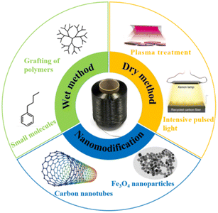
The surface of CF does not contain polar groups, so the binding force between CF and most polymer resins is weak. The surface modification performance of CF increases the active particles or sites on the surface of CF to enhance the bonding strength between the fibers and resins.4 In composite materials, commercial CF reinforcements are usually surface modified to effectively transfer stress between fibers and resins, thereby improving the interfacial strength of the composite materials. As CF has non-polar crystalline graphic basic planes, the research on the surface modification of CF is mainly achieved by increasing the active sites on the surface of CF and improving the surface micro–nano defects. The surface modification methods of CF mainly include wet methods, dry methods, and nano modification (as shown in Fig. 1). Wet methods can be divided into acid treatment, polymer modification, the electrochemical grafting of small molecules, electrochemical initiation polymerization, and the electrochemical grafting of polymers. The dry methods can be divided into plasma treatment, chemical vapor deposition, high-energy radiation modification, selective laser sintering, and other methods. Nanomodification is mainly through the introduction of nano fillers (such as carbon nanotubes, nanoclay, polythermide nanoparticles, SiO2) to modify the surface of CF, improve the micro-morphology, and thus realize the improvement of the physical and chemical properties of CF-reinforced composites.5–7 The application and advantages and disadvantages of the different modification methods are shown in Table 1.| Method | Applied theory | Advantages | Disadvantages | Applications |
|---|---|---|---|---|
| Surface oxidation | In an oxidizing atmosphere (such as air, CO2, O3, strong acid), catalytic or high-temperature and high-pressure methods are used to oxidize the surface of CFs, generating active functional groups (such as hydroxyl, carboxyl or other functional groups) | Simple operation and fewer post-processing steps | Damaged fiber surface | Osbeck et al. modified the surface structure and function of CFs by exposing them to the combined action of ultraviolet radiation and ozone.14 |
| Plasma treatment | High-energy radiation is applied to bombard the surface of CFs for introducing chemically active functional groups, such as hydroxyl, ether bonds, carboxyl groups, on the surface of CFs | High efficiency and pollution-free | Modification effect is not uniform, and the influencing factors are complex | Lew used a mixture of ammonia/ethylene gas to treat CFs, and the results showed that the interfacial shear strength of CFs was increased by 2–3 times.15 |
| Surface coating modified carbon fiber | A coating on the surface of CFs is applied through physical or chemical interactions, which can simultaneously wet the fibers and resin matrix, with the goal to improve the structure and properties of the composite material interface | Simple operation | Causes pollution | Ge et al. significantly improved the mechanical properties of CF/epoxy resin composites after tuning the size.16 |
| Vapor deposition method | Two or more gases are injected into a closed reaction chamber, causing it to undergo a chemical reaction, forming a new substance that eventually deposits on the surface of the fibers | Easy to operate and industrialize | Low gas deposition rate and flammable and explosive products | Bhuvana et al. deposited petal-shaped graphene sheets on the surface of graphite fibers using a vapor deposition method.17 |
| Electrochemical modification | Utilizing the conductive properties of CFs as the anode of the electrolytic cell, the surface of the CF is oxidized and etched under the action of electricity | Fast processing speed, easy to control | High energy consumption | Y. Li et al. significantly improved the interfacial bonding ability of composite materials by oxidizing CFs in different electrolytes.18 |
Wet methods
The essence of the wet modification of CF is to physically and chemically modify the surface of CF in a solution environment. The acid oxidation method mainly involves oxidizing the surface of CF to varying degrees by controlling the reaction temperature, reaction time, medium concentration, and other conditions. The acid oxidation method can significantly change the surface roughness of fibers. Electrochemical modification is another method for modifying the surface of CF using the CF as the anode, graphite or copper plate as the cathode, and an acid alkali salt solution as the electrolyte under the action of an electric field.Electrochemical grafting of small molecules
Amine-grafted CFs display excellent interfacial adhesion due to the effect of their equivalent crosslinking.8,9 L. Servinis et al. from Deakin University studied and compared the mechanism for CF electrochemical grafting of pendant amine, carboxylic acid, and plastic amine (N-hexyl amine) groups and explored their effects on the mechanical properties of the composites.10 The results of the interfacial shear strength tests they performed showed that the strength of CF modified with amine, carboxylic acid, and plastic amide was improved. The CF modified with amine displayed the largest increase (compared with the unmodified CF, whereby the shear strength increased by 172%). The action mechanism of CF modified by amine, carboxylic acid, and lipophilic amide to reinforce maleic anhydride-grafted polypropylene composites was also explored. The test results of the interfacial shear strength tests showed that the strength of the composite modified with amine was the largest (the interfacial shear strength increased by 64%). Amine-functionalized fibers and maleic anhydride were co-crosslinked. The action mechanism is shown in Fig. 2. | ||
| Fig. 2 Schematic of the reductive electrografting of diazo salts (left) and functional groups.10 | ||
The application of CF in the field of energy-storage materials has received widespread attention.11,12 Many researchers have focused on improving the bonding strength of CF and resin matrix for the surface modification of CF. There are few studies on the electrical conductivity of CF. K. M. Beggs et al. studied the resistance and IFSS of CF modified by different covalent groups by the electrochemical reduction of CF modified by various phenyl-diazo compounds.13 The resistance of the same surface-modified CF is shown in Table 2. The resistance of the modified CFs showed that different small molecules had different effects on the resistance of the CFs. The test results revealed that under the treatment of a high reduction potential (−1 V), the resistance increased with the increase in treatment time.
Thermoplastic polyurethane (TPU) is a thermoplastic material with similar rubber properties. TPU has high elasticity and wear resistance, and is widely used in seals and sports equipment.19 CFs are widely used to enhance the mechanical properties of TPU.20 However, the CF-reinforced TPU materials exhibit low stress-strength and steel resistance due to the weak interaction between the fibers and the matrix.21 Y. Y. Zhang, Y. Z. Zhang et al. studied a method for modifying CFs with 4,4′-diphenylmethane diisocyanate (MDI) (as shown in Fig. 3).22 Specifically, they put CFs into 0.5 mol L−1 dilute sulfuric acid solution for electrochemical treatment; the CFs were modified with acetone solution containing MDI in a nitrogen atmosphere. The SEM and atomic force microscopy (AFM) analysis results showed that the surface roughness and carbon atom disorder of the modified fibers were increased significantly; while the random distribution and stacking of modified CF in the resin matrix increased the connection points and formed a network structure; and the steric hindrance effect of the network structure hindered the movement of the polymer molecular chain and improved the hardness of the CF-reinforced TPU material. Overall, the abrasion of the modified-CF-reinforced TPU material was significantly reduced.
 | ||
| Fig. 3 Modification procedure for MDI-CF.22 | ||
Due to the good chemical inertness of polypropylene's (PP) molecular structure, the adhesion between the reinforcement and PP is poor. Generally, maleic anhydride-grafted polypropylene (MAPP) is used to improve the adhesion of the fiber matrix.23–25 CF promotes the interaction with maleic anhydride through surface oxidation. However, the interaction between the oxidized surface and PP is poor.26,27 J. D. Randall et al. used n-butyl diazonium specifications for electrochemical treatment on the surface of CFs (as shown in Fig. 4), which enhanced the non-polar molecular interactions with PP. The mechanical test results showed that the adhesion between the fibers and resin matrix was increased by 220%. The CFs with alkylated substituents interacted with the van der Waals force of the polypropylene matrix to form a ductile layer.28
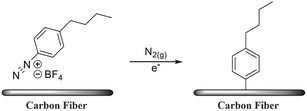 | ||
| Fig. 4 Surface modification pathway through the electrochemical reduction of n-butyl benzene diazonium tetrafluoroborate and subsequent grafting onto the CF surface.28 | ||
The carbonization and graphitization treatment in the CF preparation process eliminates the surface polarity of the CFs and gives them good chemical inertness.29–31 PAN-based CFs can be divided into standard modulus CF (230–240 GPa), medium modulus CF (280–300 GPa), high modulus CF (HMCF, 350–480 GPa), and ultra-high modulus CF (UHMCF, 500–600 GPa) according to the size of elastic modulus.32,33 Liu et al.34 reported on the electrochemical oxidation of CF and HMCF, and the research results showed that the reactivity of HMCF was lower than that of CF. There are few studies on UHMCF. X. Qian,35 J. J. Zhong, and others studied the mechanism of the electrochemical anode surface modification of UHMCF with different current densities (0, 1.0, 2.0, and 3.0 A m−2), and presented AFM images of CFs processed with different current densities (0, 1.0, 2.0, and 3.0 A m−2). Comprehensive SEM and AFM analysis showed that the surface of the CF treated with a current density (0 A m−2) contained some impurities, which arose as the by-products of the CF pyrolysis process. However, when the current density was greater than 1.0 A m−2, the surface stripes of electrochemically modified UHMCF became clearer and the impurities disappeared. The test results of ILSS regarding the mechanical properties are shown in Fig. 5. It can be seen that the modulus decreased with the increase in current density in electrochemical treatment; whereby the intensity decreased first and then increased with the increase in current density in the electrochemical treatment. Based on Raman spectroscopy analysis, it was concluded that when the current density in the electrochemical treatment increased from 0 to 1.0 A m−2, electrochemical oxidation and corrosion occurred on the fiber surface, and the value of ID/IG increased significantly, resulting in a decrease in the fiber strength. With the further increase in current density, the graphite layer on the surface of UHMCF underwent a crosslinking reaction, which increased the longitudinal or lateral cohesion on the fiber surface.
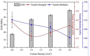 | ||
| Fig. 5 Mechanical properties of oxidized UHMCFs with different current densities and their reinforced epoxy composites.35 | ||
Terpenes are natural compounds that are widely used in the preparation of solvents and resins. Moreover, they also have good application prospects in the research into CF surface modification. The physical and chemical properties of terpineol and borneol have good compatibility with CF. The molecular structures of terpineol and borneol are shown in Fig. 6. Terpineol and borneol have the characteristics of non-polarity, which are due to, respectively, their monocyclic ring structure and bicyclic ring structure. S. S. Pawar36 et al. connected a sizing agent (terpineol and borneol) to the surface functional groups (NO2, –COOH, –NH2, –SH) to modify CF through electrochemical treatment. The mechanical properties of the composite were enhanced by the treatment of the two sizing agents, as shown through the analysis of tensile and interfacial shear strength (IFSS). The introduction of nucleophilic functional groups (such as NO2, –SH) had the greatest effect on the mechanical properties of the composites. This study shows that terpenes have high application value in the application of CF sizing treatment.
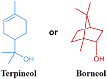 | ||
| Fig. 6 Molecular structures of terpineol and borneol.36 | ||
The basic plane and edge plane are two different types of surfaces of graphic materials.37–40 Extensive research has been carried out on the basic plane and edge plane. The basic plane and edge plane occupy a dominant position in the axial and tail ends of the fiber, respectively.37 Research shows that edge sites have higher capacitance than the basic plane.41 Using this capacitance difference, a detector can monitor the difference in carbon surface changes. The electron transfer on the surface of CFs can be attributed to the synergistic effect of conductivity and surface chemistry, which can be characterized by surface purity, surface C/O ratio, etc.42 With the application of CF-reinforced composites in aerospace, rail transportation, automobile, and other industries, the proportion is increasing.43,44 The galvanic corrosion and electrochemical degradation of CF-reinforced composites and metals have attracted extensive attention and there are more and more research studies on the surface electroactive modification of CF. In many structural materials (such as the connector between the metal and composite, and the contact edge between the metal and composite), the surface of electrically activated CFs can produce catalytic reactions, accelerate the aging of structural samples, and affect the service life of products. The oxygen diffusion current density of CF-reinforced composite materials in NaCl solution is approximately 40 μA cm−2. The anodic dissolution rates of aluminum and iron are 0.436 and 0.132 mm per year, respectively. S. U. Ofoegbu et al. conducted electrochemical treatment on the surface of CF through sodium dodecyl sulfate (SDS) to inhibit the electrochemical activity of the surface of the CF. According to the cyclic voltammetry analysis of CFRP, the cathodic peak was significantly reduced after SDS treatment (as shown in Fig. 7). The AFM analysis results showed that the introduction of SDS significantly reduced the periodicity.45
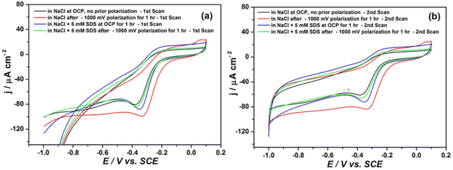 | ||
| Fig. 7 Cyclic voltammograms of CFRP in 50 mM NaCl before and after prior exposure to cathodic polarization in the presence and absence of SDS (scan rate 50 mV s−1): (a) 1st scans and (b) 2nd scans.45 | ||
Electrochemical grafting of polymers
Based on the treatment technology of electrochemically grafting small molecules to modify CF, many scholars have studied the grafting of large molecules onto the fiber surface.46 At present, there are two ways to graft large molecules onto the surface of CF: one is to graft large molecules onto the surface of a modified CF by click chemistry, and the other is to polymerize monomers on the surface of the CF by an initiator to form a polymer.47,48 Polyether ether ketone (PEEK) has a low solubility in organic solvents, and it is difficult to initiate in situ polymerization on the surface of CFs.49,50 S. Wang et al. connected an amino-terminal aniline PEEK (NH2-An-PEEK) to the surface of a CF through the reductive grading of diazonium.51 The test process is shown in Fig. 8. The results showed that in addition to the chemical bond between PEEK and the fiber, PEEK also enhanced the bonding effect through physical adsorption. The mechanical test showed that the composite's internal shear strength was increased by 130% (from 42.27 MPa to 97.33 MPa).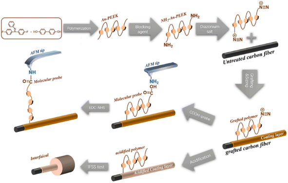 | ||
| Fig. 8 Illustration of the electrochemical grafting process and single-molecule force spectroscopy.51 | ||
The pyrolysis temperatures of PES and PEEK (>500 °C) are much higher than that of typical sizing materials (250 °C). In the case of high-temperature applications, the pyrolysis of the sizing material will form a brittle interface, seriously reducing the performance of the composite.52–54 B. Dharmasiri et al. treated CF by electrochemical grafting (the expected chemistry on the surface-modified CF is shown in Fig. 9).55 Here, the poly(o-phenylenediamine) (poly(o-PD)) layer was bound by covalent bonds; then high-temperature treatment was conducted at different temperatures. Compared with CF without sizing, the CF with this sizing surface treatment had a higher tensile strength (increased by 44.9%), modulus (increased by 15%), IFSS, and thermal stability (pyrolysis temperature >650 °C). The reason for these improvements was that the polymerization and growth made up for the weak spots on the fiber surface. Also, the interface adhesion increased by 189%. In the presence of diazonium salt (2 mM), the CF was electrografted with 20 mM o-PD, which had free amine groups on the surface, resulting in the highest IFSS through binding with the polymers and the complementary hydrogen bonds. After carbonization, the nitrogen content on the surface decreased, resulting in a reduction of IFSS.
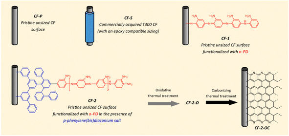 | ||
| Fig. 9 Sample nomenclature and expected chemistry of a surface-modified CF.55 | ||
D. J. Eyckens and others performed electrochemical treatment on the surface of CF through the method of covalent sizing surface modification.56 The effects of different acrylic monomer concentrations (0.1, 0.2, 0.5, 1.0, 1.5, or 2.0 M) on the tensile strength, modulus, and interfacial shear strength of modified CF were investigated. The tensile strength, modulus, and interfacial shear strength were increased by 25%, 15%, and 199%, respectively, when the modification was carried out in an aqueous environment with a constant potential of 1 V (treatment time <2 min). This would meet the requirements of large-scale industrial processing in terms of time and provides technical and theoretical support for large-scale industrial production.
Dendrimers and hyperbranched polymers were applied to modify CFs through electrochemical grafting, which improved the compatibility, wettability, and mechanical interlocking of the fibers and resins.57 M. Andideh, M. Esfandeh et al. reported a method of electrochemical grafting modification for CF composites by hyperbranched polyurethane terminated with multiple amine groups.58 The core of this method was the preparation of hyperbranched polyurethane terminated with multiple hydroxy groups (HBPU–OH), and the chemical reaction between the acidified CF and HBPU–OH was also a crucial step. Simultaneously, the optimum concentration and time of treatment at 50 °C and 20 °C were analyzed by desirability function. It can be seen from Fig. 10 that the modification method (with an electrolyte concentration of 15% w/w, 10 min, temperature of 20 °C) was the best. The comprehensive analysis by SEM, Raman, mechanical tests, and FTIR showed that the carboxylic acid groups and epoxy groups on the surface of the modified CF formed covalent bonds; while HBPU and the composite resin matrix underwent interdiffusion and mechanical interlocking at their interaction interface. Compared with the unmodified CF, the ILSS was increased from 61.7 MPa to 107.2 MPa.
 | ||
| Fig. 10 3D surface plots for the effect of concentration and time on the desirability at two temperature levels +1(left) and −1(right).58 | ||
D. J. Hayne et al. electrochemically modified the surface of CF by ring-opening methodology polymerization (ROMP).59 The core of this modification method is the reduction modification of the N–C bond (P1) and the introduction of a blocking group (P2). P1 ensured that aryldiazonium salt could be grafted onto the surface of the CF. The introduction of (P2) ensured the occurrence of the phenomenon in Fig. 11(B) in the ROMP process. David J. Hayne et al. designed seven modification methods of ROMP, and found that the tensile strength and modulus of the modified CF were not obviously changed. The internal shear strength of the modified CF was increased by 189%.
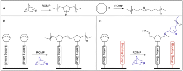 | ||
| Fig. 11 (A) Examples of some common molecular scaffolds used for ROMP, including norbornene (left) and cis-cycloctene (right) possessing strained alkenes. (B) Potential polymerization across the surface of the fiber (i.e. minimal incorporation of external monomer in blue). (C) Use of a blocking group (in red) to interrupt this process and encourage the incorporation of an external monomer in polymer growth from the fiber surface.59 | ||
Recently, some researchers have used an ethanolic dispersion of oligomeric PEKK molecules as a sizing agent to conduct surface treatment on fibers and achieved an improved thermal stability of the modified fiber (up to 500 °C).60 Y. Athulya Wickramasingha et al. connected acrylate-derived polymers with aromatic side chains to the surface of CF through electrochemical grafting modification, and chemically formed a ring reaction on the surface of the modified fiber after high-temperature treatment (the acrylamide grafted to the surface of the CF is shown in Fig. 12). Simultaneously, the effect of applying polymers with different levels of aromatic content on the properties of the modified fibers was studied. The results show that the growth of aromatic polymers on the surface of the fiber was beneficial to the thermal stability of the modified fiber. The tensile strength and modulus of the CF with a benzyl-bearing side chain increased by 20% and 7%, respectively, after being treated at 600 °C.61
 | ||
| Fig. 12 Grafting of acrylamide onto the surface of CF, followed by exposure to heat, resulting in cyclisation (right).61 | ||
The surface defects (such as bulges, grooves, micro–nano cracks, and impurities produced by high-temperature treatment) and micro-damage of CFs can seriously affect the roughness and mechanical properties of the surfaces of CFs.31,62–64 Chemical vapor deposition, electrochemical grafting, plasma treatment, and other modification methods can effectively improve the performance of CF, but the process is complex and costly. Not applicable to industrial production. X. Chen et al. of Xi'an Jiaotong University reported a modification method that did not involve surface chemical reactions.65 In order to solve the problem of incomplete infiltration, the polymer surface defects were repaired by applying an electric field to assist the polymer. The IFSS was compared before and after electrical stimulation by a microdroplet test. Simultaneously, final element analysis was carried out of the epoxy fluid behavior on a structured substrate (the flow models and final element analysis are shown in Fig. 13). The results show that under the condition of external electric field-assisted wetting, the wetting states changed from the Cassie state to Wenzel state. When the polymer droplet was completely filled with defects, the internal electric field tended to become stable. The approach for the surface modification of CF with an electrowetting-assisted polymer is of great significance for the surface defect repair and microstructure design of high-performance CF materials.
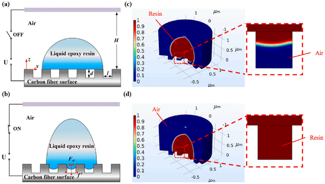 | ||
| Fig. 13 (a and b) Schematic illustrations of two-phase flow models without/with the application of a parallel electric field. (c and d) Finite element analysis of the epoxy fluid behavior on a structured substrate with and without the application of an electrical stimulus.65 | ||
Other wet methods
Poly(arylene sulfonate sulfonate) (PASS) is a thermoplastic material with high mechanical properties and a high glass transition temperature (220 °C).20 The sulfone groups in the poly(arylene sulfone sulfone) (PASS) molecular chain have strong polarity, thus producing strong intermolecular force.66 T. Zhang et al. prepared PASS-modified CF by grafting amine containing PASS (NH2-PASS) and CF with surface oxidation treatment.67 The effects of different catalysts on PASS-modified CF were studied and compared. The physical and chemical properties of CF modified by PASS with different molecular weights under the condition of the same catalyst (hexafluorophosphate azabenzotriazole tetramethyl uranium (HATU)) were further investigated. The technical route the study followed is shown in Fig. 14. The results showed that the PASS-modified CF prepared by HATU as the catalyst had higher mechanical properties. The interlaminar shear strength of the low-molecular-weight-PASS-modified CF was higher. Comprehensive analysis by AFM and mechanical tests showed that the low-molecular-weight-PASS-modified CF and the matrix had better compatibility and diversity. | ||
| Fig. 14 Schematic illustration of the reaction steps for modifications on the surface of CF.67 | ||
Styrene-butadiene rubber (SBR) has the advantages of high wear resistance, excellent processing performance, high elasticity, etc., but it also has the disadvantage of poor tensile strength. SBR is widely used in the automobile manufacturing industry.68,69 In order to improve the mechanical, thermal, and electrical properties of SBR, researchers have carried out extensive research work, including the use of a filler (carbon black, silica, etc.), and fiber modification (nylon, CF, glass fiber, etc.) with an aim to improve the strength, corrosion resistance, and thermal stability of SBR. M. Andideh et al. prepared short CF-reinforced SBR by a Hummers' method.70 First, the short CF was oxidized to form CF-OH; then tetramethylthiouram disulfide (TMTD) was grafted onto the surface of CF-OH to form CF-OH-g-TESPT through acid treatment. Finally, CF-OH-g-TESPT was grafted onto the SBR surface through a solution method to form CF-OH-g-TESPT-SBR. The tear strength of the composite increased with the increase in the content of the modified CF. When the mass fraction of modified CF was 5%, the tear strength was the highest.
Polyhedral oligomeric silsesquioxane (POSS) has a unique three-dimensional (3D) spatial cage-like structure, a unique spatial structure, and a combination of organic and inorganic main components (Si–O–Si), giving POSS both organic and inorganic chemical properties. POSS-modified composites have good thermal stability, strength and modulus. B. Gao71 et al. used poly(amidoamine) (PAMAM) as a coupling agent to modify CF with polyhedral oligomeric silsesquioxane (POSS) (as shown in Fig. 15). First, the surface of the CF was modified by amination, then the aminated CF was chemically reacted with ethylenediamine. Finally, POSS was grafted onto the surface of CF. The PAMAM and POSS-modified CFs showed improved surface roughness and wettability. The interlaminar shear strength and interfacial shear strength of the modified CF increased by 48% and 89% respectively.
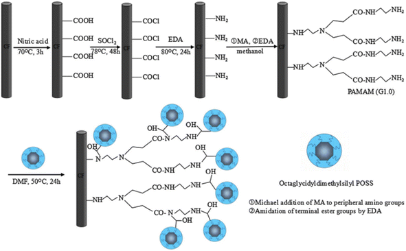 | ||
| Fig. 15 Functional-group modification on CF.71 | ||
Intrinsic self-healing interface materials can realize the self-healing of materials through reversible chemical reactions (such as a Diels–Alder (DA) reaction).72 The DA adduct is usually used in modified fiber-reinforced thermoplastic composites to endow the composites with a self-healing ability. The DA reaction and reverse DA (rDA) reaction occur at 60–90 °C and 140–190 °C, respectively, and the reaction conditions are relatively mild.73,74 Metal–organic frameworks (MOFs) can endow composites with excellent physical and chemical properties (such as elastic modulus and shear modulus). Zr-based MOF is often used to modify resin-based composites.75,76 Y. Li, B. Jiang et al. synthesized UiO-66-NH2-CF through the reaction of acidified CF and UiO-66-NH2. Then the UiO-66-M-CF was synthesized by the reaction of UiO-66-NH2-CF and maleic anhydride. Thus, the CF-reinforced epoxy composite with an interface self-healing ability was successfully prepared. The preparation process is shown in Fig. 16(a), and the self-healing mechanism in Fig. 16(b). The interface of UiO-66-M-CF and UiO-66-M-EP was subjected to three DA reactions and rDA reactions. The results showed that the self-healing efficiency could reach more than 90%.77
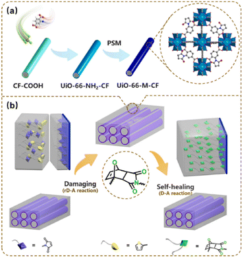 | ||
| Fig. 16 Schematic illustration of the preparation and self-healing process of UiO-66-M-CF/UiO-66-M-EP. (a) Preparation process; (b) self-healing mechanism.77 | ||
The surface sizing treatment of CF is considered to be the most simple and effective modification treatment of CF. C. Yuan et al. reported the preparation method of a new kind of sizing agent, namely a semi-aliphatic polyimide. The ILSS value of CF composites modified by it increased by 20.9%.78 The reason is that the stacking effect of π–π chemical bonds and the synergistic effect of the physical entanglement enhance the mechanical properties of the composite. Generally, high-performance thermoplastics are considered difficult to be used as sizing agents to effectively strengthen and modify the surface of CFs. The reason is that high-performance thermoplastics are prone to material degradation during processing.79 Semi-aromatic polyamide 6T (PA6T) is a new thermoplastic material with high performance. Its molecular chain contains a large number of rigid aromatic segments. PA6T not only has high thermal stability, but also easily processed aromatic chain segments. Z. Wang et al. studied a modification method involving the in situ polymerization of PA6T on the surface of CF.80 First, the oligomer of PA6T (PRE-PA6T) was synthesized by a solution–solid-phase one-pot polycondensation technique. Then a suspension of PRE-PA6T and ethanol was prepared (through the interaction of amide and hydroxyl with strong polarity). In step 3, CF was added into the suspension, followed by the high-temperature polycondensation reaction in vacuum on the sized CF. The micro-morphology and mechanical properties of four micro bond test specifications were prepared and investigated. The results show that the in situ polymerization of PA6T could effectively improve the mechanical properties of composites by forming a buffer zone on the surface of the fiber and matrix.
ACN((NH4)2·Ce(NO3)6) is a strong oxidant with low toxicity and is easily soluble in a variety of organic and inorganic solvents. J. Y. Cai et al. carried out surface oxidation modification of CF using ammonium cerium nitrate (ACN) at near room temperature (20 °C, 50 °C).81 The fiber morphology and mechanical properties under different treatment temperatures and oxidant concentrations were investigated. SEM analysis showed that with the increase in ACN treatment time, the particles deposited on the surface of CF increased gradually. Ce2O3 and CeO2 produced by the oxidation treatment of the CF surface by ACN formed coordination complexes with oxygen-containing functional groups on the surface of CF. The surface energy, specific surface area, and reactivity of CF were improved, where the IFSS and ILSS increased by a maximum of 304% and 130%, respectively. The research showed that the surface modification of CF by ammonium cerium nitrate at near room temperature has high application prospects and value.
M. Bauer et al. compared the mechanism of the anodic oxidation treatment of CF under the conditions of alkaline and acid electrolytes.82 Among the test conditions, the pH value of the adopted alkaline aqueous ammonium bicarbonate solution was 8, and the pH value of the selected acid solution was 2. The difference between static anodic oxidation and dynamic anodic oxidation at different pH values was further compared. The results showed that the oxidation degree of CF treated with dilute sulfuric acid electrolyte was higher, while there was no significant difference in COOH concentration between the static anodizing and dynamic anodizing.
Q. Wu et al. reported a way to introduce a simple anti-sandwich structure into CF.83 The anti-sandwich structure was composed of two layers of flexible polymer amine and stiff and tough graphite oxide. The anti-sandwich structure could effectively prevent crack growth, and the IFSS and international toughness of the composites were increased by 48.7% and 94.4% respectively.
Dry methods
The commonly used dry modification methods for the surface modification of CF include plasma treatment, high-energy irradiation, and heat treatment. Plasma treatment can change the surface free energy of CF and further improve the microstructure of the fiber surface through surface etching, thereby enhancing the interface performance between the fiber and the resin matrix. Plasma treatment is beneficial for further chemical grafting modification of the CF surface. The surface modification of CFs by high-energy irradiation, accompanied by the presence of sputtering and ion induced diffusion, results in the formation of nanoscale structures (i.e., the generation of nano ripples) on the fiber surface. High-energy irradiation can displace atoms, improve the fiber surface roughness, generate active sites, and enhance the interface bonding ability with the matrix.Plasma treatment
E.-s. Lee et al. of Korea University reported a method for treating CF with hydrogen plasma and oxygen plasma respectively,84 and studied its effect on carbon-fiber-reinforced polyetherimide composites. This method applied 450 W radiofrequency plasma power, which could change the flow rate of oxygen or hydrogen injection into the chamber (flow rates from 10 to 50 sccm). The FTIR results showed that there was C![[double bond, length as m-dash]](https://www.rsc.org/images/entities/char_e001.gif) C double bonds at about 1565 cm−1 in the CF treated by oxygen plasma. C
C double bonds at about 1565 cm−1 in the CF treated by oxygen plasma. C![[double bond, length as m-dash]](https://www.rsc.org/images/entities/char_e001.gif) O stretches of ketone and carboxyl groups appeared between 1680 and 1710 cm−1, while the peak for the OH functional group was between 3675 and 3685 cm−1. The mechanical properties at room temperature and 150 °C were also investigated. The results show that the mechanical properties of CF treated by hydrogen plasma were the best at room temperature and high temperature (150 °C).
O stretches of ketone and carboxyl groups appeared between 1680 and 1710 cm−1, while the peak for the OH functional group was between 3675 and 3685 cm−1. The mechanical properties at room temperature and 150 °C were also investigated. The results show that the mechanical properties of CF treated by hydrogen plasma were the best at room temperature and high temperature (150 °C).
CF is widely used in the preparation of laminated composites. The fracture toughness of CF-reinforced laminated composites can be improved by reducing the crack propagation of weak links by carefully designing the fracture sequence and fiber direction.85–88 During the preparation of CF-reinforced laminated composites, the phenomenon of oil penetration of the composites could easily occur, which then reduced the mechanical properties and heat resistance of the composites.89 The resin matrix used for CF-reinforced laminated composites has low thermal conductivity in the vertical direction of the CF, which leads to the problem that vertical thermal diffusion is blocked.90,91 In order to improve the thermal conductivity of CF-reinforced laminated composites in the vertical direction of the ply, scholars have carried out a lot of research, such as the introduction of nano-conductive fillers. Although this method improves the thermal conductivity of CF-reinforced laminated composites, it will reduce the interfacial bonding strength of the composites.92,93 J. An, J.-W. Kim et al. through layer-by-layer plasma surface treatment reported an enhancement in the mechanical properties and oil repellency of the fibers,94 and also an improved thermal conductivity of the CF-reinforced laminated composites in the vertical direction. The layer-by-layer plasma surface treatment process is shown in Fig. 17. The multi-layer oxidation structure was formed by layer-by-layer plasma surface treatment, which could not only enhance the adhesion between interfaces, but also introduces hydrophilic groups, such as C–O and C![[double bond, length as m-dash]](https://www.rsc.org/images/entities/char_e001.gif) O. The results showed that the mechanical properties (as shown in Fig. 18), thermal conductivity, and oil resistance of the composites were significantly improved with the increase in treatment time from 439 s (plasma 13 kJ) to 1318 s (plasma 39 kJ).
O. The results showed that the mechanical properties (as shown in Fig. 18), thermal conductivity, and oil resistance of the composites were significantly improved with the increase in treatment time from 439 s (plasma 13 kJ) to 1318 s (plasma 39 kJ).
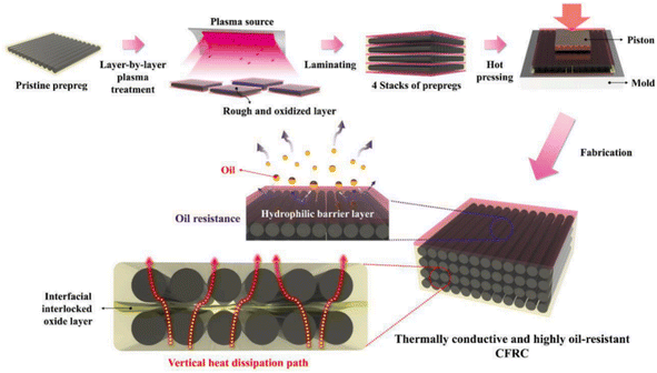 | ||
| Fig. 17 Schematic illustration of the fabrication process for obtaining thermally conductive and highly oil-resistant CFRC materials.94 | ||
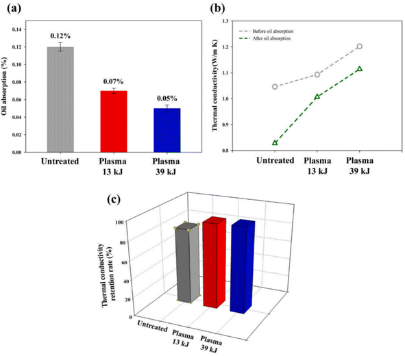 | ||
| Fig. 18 (a) Oil absorption rate (%) and (b) vertical thermal conductivity of the fabricated CFRCs. (c) Thermal conductivity retention rate (%) of the CFRCs after oil absorption tests.94 | ||
Activated CF (ACF) is a high-performance solid adsorption material with an excellent specific surface area, fiber strength, and uniform micro–nano pore structure.95,96 Due to the good chemical inertness of ACF and the lack of surface functional groups, ACF has good hydrophobicity. Generally, water molecules form hydrogen bonds with oxygen-containing functional groups to realize the formation and growth of water droplets.97–99 Due to the poor hydrophilicity of ACF, it is necessary to modify ACF to realize its potential application value in the field of water-absorbing materials. Acid treatment (such as nitric acid and sulfuric acid) on the surface of ACF is conducive to achieving the hydrophilicity of ACF. However, the waste liquid from acid treatment can easily pollute the environment. However, low-temperature plasma (LTP)-modification treatment has the characteristics of an acceptable treatment time, simple operation, and environmental friendliness.100–102 Y. Huang et al. modified ACF by low-temperature oxygen plasma (LTOP).103 The effects of the plasma treatment time (3, 5, 15, 30, 60 min) and output voltage (7, 8, 9, 11 kV) were studied. The results showed that LTOP treatment could increase the number of adsorption sites on the surface of CF. Through image analysis of the six adsorption–desorption cycles (at 25 °C and 40% RH) (as shown in Fig. 19), it could be observed that there was no difference in the adsorption performance of the six cycles of ACF, and that the water absorption of ACF modified by LTOP was significantly enhanced. This technology is conducive to the application of ACF materials at room temperature and low humidity.
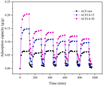 | ||
| Fig. 19 Water vapor adsorption stabilities of activated carbon fiber samples, namely ACF-raw, ACFL8-15, and ACFL8-30.103 | ||
Carbon nanotubes can be prepared from ethanol at low temperature. A variety of hydrocarbons can be used as precursor materials for pyrolytic carbon, which is widely used for the surface modification of CF due to its adjustable microstructure and compactness.104–106 Pyrolytic carbon coating (PyC) can effectively modify the fiber surface and reduce surface defects. However, due to the existence of impurities and interface effects on the fiber surface, the interaction between the pyrolytic carbon and CF surface is constrained, which can result in an obstruction of the internal-load-transfer effect at the interface of pyrolytic carbon-modified CF-reinforced composites, which also affects the mechanical properties of the composites. Plasma-modified CF is often used to modify the surface functionality of CF, change the surface roughness, and improve the combination of the fiber and other materials.107 J. Sun, F. Zhao et al. reported a method for combining ethanol pyrolysis carbon deposition with plasma modification.108 The treatment process was divided into two steps: plasma treatment with a flow rate of 30 ml min−1 of helium gas, and then high-temperature treatment at 800 °C with the use of ethanol as the precursor of pyrolytic carbon. SEM images of the single-fiber pull-out test samples are shown in Fig. 20. The comprehensive analysis results of the single-fiber pull-out test and the SEM images showed that the surface of the CF modified by plasma and pyrolytic carbon deposition was modified, and the single-fiber pull-out strength was increased by 15.7%. Also, the load transfer between fiber and epoxy resin matrix was significantly improved, and the IFSS increased by 27.9%. Compared with anodic oxidation and polymer sizing, this modification method had a more obvious effect on the mechanical properties.
 | ||
| Fig. 20 Fracture morphologies of single-fiber pull-out samples: (a) as received; (b) PyC coated without plasma treatment; and (c) PyC coated after plasma treatment.108 | ||
D. Gravis et al. explored the effect of different treatment methods of plasma polymerization (gas acetylene,109 liquid HMDSO, acid acid) on the surface free energy of CF. The results show that the surface free energy of CFs treated with different plasma-polymerization treatments was 22 mJ m−2, which was lower than the surface free energy of untreated CF (27 mJ m−2). In the process of treating the surface of CF by the plasma deposition of acetylene, when the discharge power increased from 20 to 40 W, the surface energy increased from 30 to 35 mJ m−2. The effect of the plasma deposition of acetylene on improving the surface wettability of CF was thus better.
J. Lin et al. explored the effects of three different atmospheric pressure plasma treatments, namely argon (Ar), nitrogen (N2), and air (air), on the surface properties of CFs.110 The AFM research results are shown in Fig. 21. With the extension of treatment time from 1.5 s to 7.5 s, the surface roughness of the fiber treated by N2 plasma was the highest, and that of the fiber treated by air plasma was the lowest; simultaneously, the influence of –NH2 and –OH groups on the interface bonding strength of CFRP joints was quantitatively analyzed and compared, and the effect of the –OH groups was more obvious.
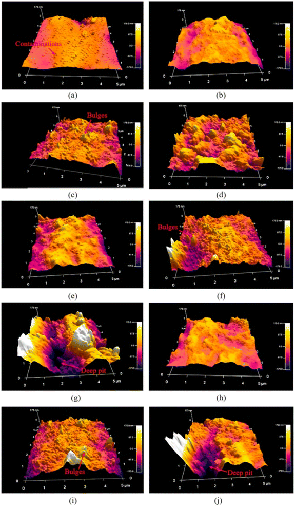 | ||
| Fig. 21 AFM images of CFRP substrate surface (a) as received, and with Ar plasma treatment for (b) t = 1.5 s, (c) t = 4.5 s, (d) t = 7.5 s; N2 plasma treatment for (e) t = 1.5 s, (f) t = 4.5 s, (g) t = 7.5 s; and air plasma treatment for (h) t = 1.5 s, (i) t = 4.5 s, (j) t = 7.5 s.110 | ||
High-energy-irradiation modification
N. N. Andrianova111 et al. investigated the effect of different ion radiations on the surface structure of CFs by treating CFs with 30 keV ion radiation (C+, N+, N2+, Ar+ ions). SEM images of the ion radiation-modified CFs are shown in Fig. 22. After treatment with 30 keV N + ion radiation (400 °C), the fiber surface showed a more obvious corroded structure, with the least surface defects, while after 30 keV C + ion radiation (350 °C) treatment, only ridges were formed in the periphery of the fiber. From the SEM images, it can be determined that when the ion association flux changed, a transition occurs from the fiber structure to a micro–nano-scale corroded structure.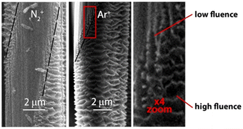 | ||
| Fig. 22 SEM images of the masked areas of the PAN-based CF surface after 30 keV irradiation with N2+ and Ar+ ions at 250 °C. The boundaries of the masked areas are marked with a dotted line and an enlarged image of the transition area is also shown.111 | ||
Other dry methods
With the development of CF manufacturing industry, a large amount of CF waste will occur. Recycled CFs (rCFs) have a broad market application prospect, although their performance is worse than that of commercial CFs. Intensive pulsed light (IPL) is a modification technology that utilizes short time irradiation. IPL modification technology has the advantages of a short time consumption, simple treatment process, and less impurity products. M. Kim et al. modified the surface of rCFs through IPL,112 and explored the interface properties of IPL-modified rCFs-reinforced high-density polyethylene (HDPE) composites. A schematic diagram of the surface modification of rCFs by IPL is shown in Fig. 23. Under the condition of 1200 V IPL modification, the rCFs surface reached the maximum value (50.3 mN m−1). The results of IFSS showed that under the condition of 1200 V IPL-modified treatment, IFSS reached 35.0 MPa, 1.93 times higher than the value for the untreated rCFs-modified HDPE composite. The XPS results and MD simulation showed that the C–O and C![[double bond, length as m-dash]](https://www.rsc.org/images/entities/char_e001.gif) O bonds produced after IPL modification were the key factors to improving the interfacial bonding strength.
O bonds produced after IPL modification were the key factors to improving the interfacial bonding strength.
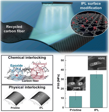 | ||
| Fig. 23 IPL-irradiated rCF.112 | ||
Selective laser sintering (SLS) is a kind of molding processing method through the laser sintering of materials. Selective laser sintering (SLS) has the characteristics of a fast molding speed and availability of a wide range of processing materials (such as ceramic, metal, polymer materials). W. Jing et al. enhanced Nylon 12 composite powder (CF/PA12) through the SLS processing of CF.113 The mechanism of the oxidation sintering behavior of CF/PA12 and the mechanical properties of the processed sample were studied. The results showed that the oxygen functional groups on the surface of HNO3-modified CF were decreased due to pyrolysis after SLS treatment, and the mechanical properties of the composite were decreased due to the increase in the internal pores. Under the protection of N2, the tensile and bending properties of the sample were significantly improved by SLS treatment (400 °C).
With the progress of science and technology, more and more electronic products have been applied to aid people's daily lives, and with this the problem of electronic interference (EMI) has become more serious. EMI shielding refers to the absorption or reflection of unwanted electrical waves through specific materials.114,115 Metal materials can reflect electromagnetic waves, but they also produce secondary electrical interference. Some composites have become the research focus of EMI shielding materials (such as foam materials, aerogel materials, aerogel-like materials). The electrospinning technique is one way to prepare high-performance micro–nano fiber materials by optimizing certain technical parameters.116–118 B. D. S. Deeraj et al. prepared TiC-embedded PAN fibers from different proportions of mixed powder (TiC powder and PAN powder) through electrospinning technology.119 Then, by carbonization and other steps, TiC@TiO2 loaded CF/epoxy composites were prepared. The XRD analysis results showed that the embedded titanium carbide oxidized to produce titanium oxide, which was then further in situ oxidize to form a titanium carbide/titanium oxide core–shell structure. The TEM images of CFs prepared by mixing with TiC powder and PAN powder with different proportions are shown in Fig. 24. T11 had the best shielding performance (158.61 ± 0.95 dB mm−1).
 | ||
| Fig. 24 TEM micrographs of TiC-loaded PAN fibers, (a) PAN alone, (b) PAN/TiC (3/1), (c) PAN/TiC (2/1), and (d) PAN/TiC (1/1).119 | ||
T. Takeda et al. adopted ITRO technology to cover a SiO2 film onto CF surface by combustion chemical vapor deposition (CCVD). The effects of the ratio of the gas to air, the gas/air flow rate, and the concentration of silane compounds on the interfacial properties of CF-reinforced composites were investigated. The results showed that the shear strength of CFRP single-lap joint specimens was significantly improved by repeated ITRO treatment.120
T. Naganuma et al. explored the repair mechanism of the surface defects of high-strength CF (T1000GB) by a high-performance vapor deposition polymerization process (VDP).121 First, a 10–100 nm deep notch was created on the surface of CF through the FIB system (as shown in Fig. 25(a)). The results showed that when the depth of notches was less than 30 nm, the repair effect of the VDP coating was obvious, which could effectively penetrate nano-notches. By using the same (pyrolytic dianhydride (PMDA) and 4-40-oxydianiline (ODA)) monomers, VDP had a stronger repair effect on CF than the impregnation process (fiber strength increased by 25%).
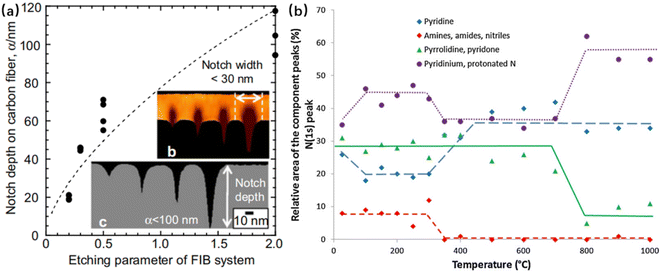 | ||
| Fig. 25 (a)Infiltration of the polyimide coatings into the surface notches on the T1000GB CF. Nano-ordered notches introduced by the FIB technique; (b) evolution of the relative area of the peak components of the N(1s) peak as a function of the temperature.121,122 | ||
F. Vautard et al. explored the effect of different temperatures (from room temperature to 1000 °C) on the surface functional groups of CFs.122 XPS analysis results showed (see Fig. 24(b)) that amines, amides, and nitres were stable at temperatures below 300 °C, but from 350 °C to 600 °C, the Ph–OH bonds decreased and C–O–C increased.
Nanomodification
Nanoparticles are generally used to modify the surface of CFs by means of electrochemical modification, chemical vapor deposition, hydrothermal method, etc., and can improve the surface microstructure of CFs, reduce fiber surface defects, and improve the load-transfer efficiency between the fibers and resin matrix.As a bioceramic material, boehmite has good heat resistance and chemical stability, and is widely used in the production of drug carriers, catalyst carriers, and flame retardants.123–126 D. K. Trukhinov et al. modified the surface of CF through incorporating a seed-assisted hydraulic fabric.127 First, the (molar ratio of Al3+/NO3 was 5/1) boehmite sol was prepared by using nine-hydrate aluminum nitrate and ammonium hydroxide aqueous solution (Al(NO3)3 × 9H2O) and nitric acid. The surface of the CF treated with nitric acid was modified to form a seed layer. Finally, a nano-structured boehmite-modified CF was prepared by hydrothermal modification (the modification process is shown in Fig. 26(C)). The analysis by SEM and Raman spectroscopy showed that there was hydrogen bonding between the seed film layer and boehmite nanoflakes. The seed layer contributed to the aggregation of surface nanoparticles to form an embedded structure of boehmite particles. The tensile strength of the boehmite-modified CF-reinforced ABS plastic was increased by 56% (from 12.17 MPa to 18.99 MPa).
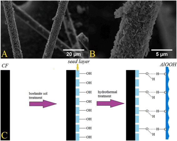 | ||
Fig. 26 SEM images of CF after two-stage modification (CF_HTmod) at 5000 (A) and 30![[thin space (1/6-em)]](https://www.rsc.org/images/entities/char_2009.gif) 000 magnifications (B); scheme of the interaction of a seed film layer with γ-AlOOH nanoparticles (C).127 000 magnifications (B); scheme of the interaction of a seed film layer with γ-AlOOH nanoparticles (C).127 | ||
Because of its unique adhesion protein, marine organism mussels can co-exist with diphenol and amine groups. Inspired by this phenomenon, polyamine formed by the spontaneous oxidative polymerization of dopamine can serve as a bridge for CNT-modified CFs because of its large amount of catechol and amine functional groups.128,129 N. Xu, Y. Li et al. prepared CF-PDA by placing CF and dopamine in tris (hydroxymethyl) aminomethane (Tris) buffer solution (as shown in Fig. 27).130 CF-PDA/CNT was successfully prepared by introducing CNTs and the formation of amide bonds between PDA and CNT. The CF-PDA/CNT cooperatively enhanced the bonding strength of CF epoxy resin matrix through chemical bonds, hydrogen bonds, π–π interactions, and physical interactions. The PDA molecules and CNTs formed an interpenetrating network, so that the load could be effectively transferred from the resin to the fiber, and the tensile strength of the modified CF increased by 14.73%, the interfacial shear strength of the composite increased by 89.72%, and the interlaminar shear strength increased by 55.44%. Yao et al.131 reported a CNT-modified CF prepared by CVD at ultra-low temperature. When the growth temperature of carbon nanotubes was 400 °C, the IFSS and ILSS of the modified CF-reinforced epoxy resin composites were the largest.
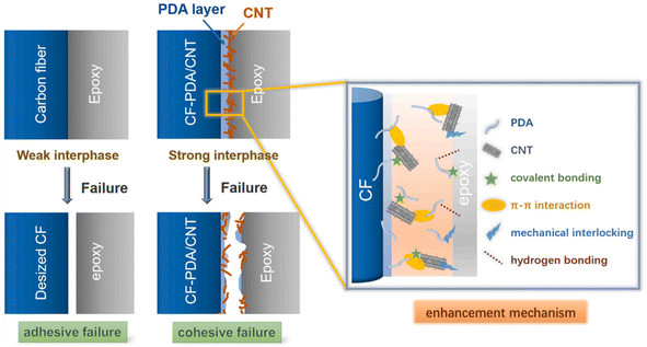 | ||
| Fig. 27 Schematic diagrams showing the failure of the fiber/epoxy interface and the enhancement mechanism.130 | ||
The low volume fraction, poor dispersion, and low orientation of CNTs may lead to the poor mechanical properties of CNT-modified materials.132,133 The surface of CNTs is usually treated with sulfuric acid and nitric acid. After treatment, there are oxygen functional groups on the surface of the CNTs, which improves their wettability. T. Kim, J. Shin et al. successfully proposed a new method for carbon nanotube surface modification fiber treatment by a two-step method (as shown in Fig. 28).134 The first step was to introduce carboxyl: where at 60 °C, the carbon nanotubes were treated with concentrated sulfuric acid containing 4-aminobenzoic acid (ABA) and sodium nitrite (NaNO2). The second step was to conduct chemical reactions with aniline derivatives to introduce the required functional groups. Through the analysis of XPS and FTIR results, carboxyl, amino and fluoromethyl groups were confirmed to be successfully introduced. It was speculated that the polymer material grown on CNT beam during the functionalization process was the main reason for the strength increase. The IFSS between CNTF and epoxy resin was measured by a microdroplet test, and it was found that the permeation behavior of the resin to nanopores could be adjusted by surface treatment.
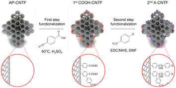 | ||
| Fig. 28 Schematic representation showing the surface treatment of CNTF proposed in this work.134 | ||
As a nano-reinforced filler, nanoclay has the advantages of high thermal stability, low thermal conductivity, and low thermal expansion coefficient.135,136 O. Zabihi et al. reported a method for modifying CF with Si-nanoclay.137 First, the CF was modified by glycidyltrimethyll ammonium chloride (GTMAC). In the second part, Si-nanoclay was modified by amino functionalization through (3-aminopropyl) triethoxysilane (APTES); finally, the Si-nanoclay was grafted onto the surface of CF by a cation exchange process. The results showed that the surface friction coefficient of the Si-nanoclay-modified CF was increased from 0.112 ± 0.00218 cN to 0.124 ± 0.00416 cN. The existence of Si-nanoclay reduced the surface defects of the fiber, increased the physical interaction with the epoxy resin matrix, and facilitated the transfer of load from the resin to the fiber. The interfacial shear strength (IFSS) of the Si-nanoclay-modified CF and epoxy resin matrix was increased by 33%.
Carbon nanotubes and nano-graphite particles have good mechanical properties at room temperature and low temperature, and can be used as nano-modified dispersants for CF-reinforced composites.138–141 The oxidation site in graphene oxide can enhance the interaction between CF and resin matrix, thus improving the shear strength of fiber-reinforced composites.4,142,143 M. Manu, K. E. R. Roy et al. reported coupling nano-graphite oxide after ultrasonic dispersion treatment with (3-aminopropyl) triethoxysilane, and silane for treating graphene oxide.144 The silane-functionalized graphene oxide was electrophoretically deposited on the surface of PAN-based CFs by a constant voltage of 30 V and a direct current of 6 A (30 min). The silane-functionalized graphene oxide-modified CF was thus successfully prepared. Comprehensive tests and analyses were performed, including tensile, flexible, and Charpy impact tests, and FTIR and microscopic morphology analyses. The results showed that the introduction of flexible Si–O–Si bond improved the toughness of the CFRP material. At room temperature and low temperature, the mechanical properties of the CFRP materials were greatly improved. Also, the surface roughness of the fiber increased with the increase in the content of graphene oxide, and the wettability of the fiber surface also improved. When the concentration of graphene oxide reached a certain level, agglomeration occurred, resulting in the decline of the mechanical properties of CFRP materials.
P. Zhu145 of Shinshu University and others introduced polyetherimide nanoparticles (PEI) on the surface of CF by means of an evolution-induced surface modification. The results showed that PEI formed nanoparticles under the action of surface tension. Simultaneously, the size of the polyetherimide nanoparticles increased with the increase in PEI concentration in N-methyl-2-pyrrolidone (NMP) solution. Through SEM analysis, it was observed that when the PEI concentration was low, a PEI coating formed on the surface of CF, and when the PEI concentration reached 0.2%, polyetherimide nanoparticles were gradually formed. Compared with untreated CF, the IFSS value of the PEI (0.2% concentration)-modified CF increased by 44.0%.
Scholars have also applied a polyol-assisted fabric of magnetic nanoparticles to the surface modification of carbon nanotubes.146,147 M. Zhang et al. reported a polyol-assisted fabric of Fe3O4 nanoparticles-modified CF strategy148 (as shown in Fig. 29). First, CFs@Fe3O4 was prepared by FeCl3·6H2O and CF through the hydrothermal method. Then, under alkaline conditions, CFs@Fe3O4@SiO2-1 was prepared through the reaction of tetraethoxysilane (TEOS, 95%) and CFs@Fe3O4. NiCl2·6H2O and CFs@Fe3O4 @SiO2-1 were used to prepare CFs@Fe3O4@NiSiO3-1 by hydrothermal treatment. Finally, the CFs@Fe3O4 @SiO2–C/Ni composite product was successfully prepared through the steps of dopamine polymerization and carbonization. The results showed that for CF@Fe3O4-1, the average diameter of the Fe3O4 spheres was 185 nm. Fe3O4 attached to the magnet takes about 30 seconds; CF@Fe3O4-2 (average diameter of the Fe3O4 spheres is 8 nm). The sample attached to the magnet takes about 80 seconds.
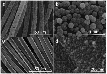 | ||
| Fig. 29 SEM images of CFs@Fe3O4-1 (a and b) and CFs@Fe3O4-2 (c and d).148 | ||
Hoecker et al. showed that the crystallinity of thermoplastic materials has an impact on the interfacial properties of CF-reinforced composites.149 S. J. See et al. covered a layer of Al2O3 membrane on the surface of CF through the sol–gel method,150 thereby affecting the crystallization degree of isotactic polypropylene (i-PP) on the surface of the CF. The results showed that there was only physical interaction between Al2O3 and CF, and no chemical reaction occurred. The polarized optical microscopy (POM) image showed (as shown in Fig. 30) that the nucleating ability of Al2O3 was stronger than that of CF. The crystallinity of i-PP on the surface of Al2O3-modified CF was improved and the crystal size was reduced, while the ILSS value was increased by 60%.
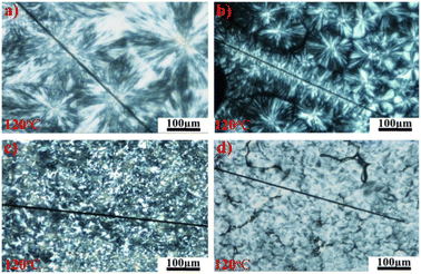 | ||
| Fig. 30 POM photographs of PP films on CFs; (a) UCF, (b) DCF, (c) UCF_AlOOH, and (d) DCF_AlOOH.150 | ||
K. Subhani151 et al. successfully modified the surface of CF (MO-CF) with MnO2-nanowhistlers by a hydrothermal method (as shown in Fig. 31). The capacity of the MO-CF-integrated supercapacitors was 120 times higher than that of the CF-integrated supercapacitors. The results showed that due to the growth of MnO2-nanowhistlers on the surface of CF, porous nanostructures with high specific surface area were formed, which provided ion-transfer channels, and so the charge storage capacity of the CF was improved.
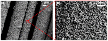 | ||
| Fig. 31 SEM images of MO-CF at (a) low and (b) high magnification.151 | ||
CFs with oxygen-containing functional groups on the surface are negatively charged in water and can be combined with positively charged polymers.152,153 T. Yamamoto et al. improved the IFSS of CF-reinforced thermoplastic materials by impregnating CF into n-butanol solution containing PMMA. The results showed that n-butanol had good wettability on CF and could improve the adsorption of PMMA particles on the surface of CF.154
W. Shen et al. explored the mechanism of the synergetic modification of CFs by carbon nanotubes and octa-aminopropylene polyhedral oligomeric silsesquioxane (OA-POSS). The –NH of the CNTs and POSS combined with –COOH on the surface of CF. The CNTs/POSS formed a transition layer between the CF and epoxy resin, which was conducive to load transfer. When the mass fraction of CNTs was 1%, the mechanical properties of the modified composites were the best.155
G. Quan156 et al. successfully reported a modified CF with a biological fish-scale structure on its surface. First, the CF was covered with a layer of polyethylene (PEI), and then the graphene oxide (GO), polyethylene (PEA), and carbon nanotube layer-by-layer assembly. Here, π–π interactions between the graphene oxide and carbon nanotubes were produced on the surface of the CFs, and chemical bonding between GO/PEA/CNT. The physical and chemical connection with the resin matrix was also synergistically enhanced, and so the interlaminar shear strength and bending strength of the composite were greatly improved.
W. M. Caceres-Ferreira et al. successfully reported a method involving the microwave-assisted growth of TiO2 nanowires on the surface of CFs. First, the surface of the CF was treated with nitrogen plasma. Then, TiO2 was seeded on the CF by a microwave-assisted method. Then, the radial growth of TiO2 nanowires on the surface of the CF was carried out. The SEM analysis results showed (as shown in Fig. 32) that the TiO2 nanowires on the surface of the CF without nitrogen plasma treatment were not uniformly distributed and agglomerated; whereas the TiO2 nanowires on the surface of CF treated by nitrogen plasma were uniformly distributed and grew radially. The surface of the CF was treated by plasma, resulting in graphitic-N, which then promoted the formation of CF–N–O–TiO nuclei and further led to the radial growth of TiO2 nanowires.157
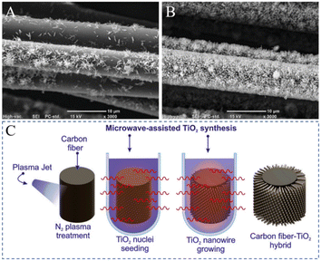 | ||
| Fig. 32 Micrographs of TiO2 nanowires grown on CF (C). (A) N-G, (B) NS-G; microwave-assisted TiO2 synthesis.157 | ||
Summary and prospect
CF, as a high-performance fiber material, has excellent characteristics, such as high axial tensile strength, high modulus, excellent chemical stability, and excellent thermal stability. Therefore, CF is widely used as a reinforcing material in composite materials. In this review, the surface modification work of CFs is summarized. We explored methods such as dry modification, wet modification, and nano modification, and further explored the impact of modification methods on the interface performance between CFs and the resin matrix. At present, scholars have conducted extensive research on electrochemical modification, plasma treatment, hydrothermal modification, and other methods, and explored the applicability of modification methods to different matrices.Overall, scholars have conducted comprehensive and extensive research work. However, the standardization of testing during the exploration process by different scholars is relatively low, making it difficult to give a more intuitive comparison. This restricts the research and development of high-performance CF materials. A standardized testing system for CFs needs to be established to better compare and promote the preparation and development of high-performance CF materials. The current research work lacks the exploration of the issues needed for large-scale industrialization. In this regard, we hopes to further explore the large-scale industrial research of CF surface modification in future research work to promote the preparation and development of high-performance CF materials and their wide-scale use.
Data availability
Data availability is not applicable to this article as no new data were created or analyzed in this study.Author contributions
Yifan Wu article writing, literature research, typesetting. Xingcai Peng article writing, literature research, typesetting. Ziming Wei literature research.Conflicts of interest
There are no conflicts to declare.Acknowledgements
The authors appreciate the support by Beijing FRP Institute Test Center Co., Ltd (research projects: study on fracture toughness of Fiber Reinforced Composites-1011), as well as the technical support by Institute of Advanced Structure Technology (Beijing Institute of Technology).Notes and references
- N. Raphael, K. Namratha, B. N. Chandrashekar, K. K. Sadasivuni, D. Ponnamma, A. S. Smitha, S. Krishnaveni, C. Cheng and K. Byrappa, Prog. Cryst. Growth Charact. Mater., 2018, 64, 75–101 CrossRef CAS.
- Y. D. Liu and S. Kumar, Polym. Rev., 2012, 52, 234–258 CrossRef CAS.
- F. R. Jones, J. Adhes. Sci. Technol., 2010, 24, 171–202 CrossRef CAS.
- X. Q. Zhang, X. Y. Fan, C. Yan, H. Z. Li, Y. D. Zhu, X. T. Li and L. P. Yu, ACS Appl. Mater. Interfaces, 2012, 4, 1543–1552 CrossRef CAS PubMed.
- B. O. Boskovic, V. B. Golovko, M. Cantoro, B. Kleinsorge, A. T. H. Chuang, C. Ducati, S. Hofmann, J. Robertson and B. F. G. Johnson, Carbon, 2005, 43, 2643–2648 CrossRef CAS.
- F. L. Jin, S. Y. Lee and S. J. Park, Carbon Lett., 2013, 14, 76–88 CrossRef.
- W. Li, L. Liu and B. Shen, Fibers Polym., 2013, 14, 1515–1520 CrossRef CAS.
- K. M. Beggs, M. D. Perus, L. Servinis, L. A. O'Dell, B. L. Fox, T. R. Gengenbach and L. C. Henderson, RSC Adv., 2016, 6, 32480–32483 RSC.
- K. M. Beggs, L. Servinis, T. R. Gengenbach, M. G. Huson, B. L. Fox and L. C. Henderson, Compos. Sci. Technol., 2015, 118, 31–38 CrossRef CAS.
- L. Servinis, K. M. Beggs, C. Scheffler, E. Wolfel, J. D. Randall, T. R. Gengenbach, B. Demir, T. R. Walsh, E. H. Doeven, P. S. Francis and L. C. Henderson, Carbon, 2017, 118, 393–403 CrossRef CAS.
- R. B. Moghaddam and P. G. Pickup, J. Solid State Electrochem., 2015, 19, 2843–2848 CrossRef CAS.
- A. G. Gunyaeva, L. V. Chursova, L. V. Cherfas and O. A. Komarova, Polym. Sci., Ser. D, 2016, 9, 228–233 CrossRef CAS.
- K. M. Beggs, J. D. Randall, L. Servinis, A. Krajewski, R. Denning and L. C. Henderson, React. Funct. Polym., 2018, 129, 123–128 CrossRef CAS.
- S. Osbeck, R. Bradley, C. Liu, H. Idriss and S. Ward, Carbon, 2011, 49, 4322–4330 CrossRef CAS.
- C. Lew, F. Chowdhury, M. V. Hosur and A. N. Netravali, J. Adhes. Sci. Technol., 2007, 21, 1407–1424 CrossRef CAS.
- H. Ge, X. Ma and H. Liu, J. Appl. Polym. Sci., 2015, 132, 2843–2848 Search PubMed.
- T. Bhuvana, A. Kumar, A. Sood, R. H. Gerzeski, J. Hu, V. S. Bhadram, C. Narayana and T. S. Fisher, ACS Appl. Mater. Interfaces, 2010, 2, 644–648 CrossRef CAS PubMed.
- Y. Li, F. Zhao, Y. Song, J. Li, Z. Hu and Y. Huang, Appl. Surf. Sci., 2013, 266, 306–312 CrossRef CAS.
- H. J. Qi and M. C. Boyce, Mech. Mater., 2005, 37, 817–839 CrossRef.
- R. A. Correa, R. C. R. Nunes and W. Z. Franco, Polym. Compos., 1998, 19, 152–155 CrossRef CAS.
- S. Y. Fu and B. Lauke, Compos. Sci. Technol., 1996, 56, 1179–1190 CrossRef CAS.
- Y. Y. Zhang, Y. Z. Zhang, Y. Liu, X. L. Wang and B. Yang, Appl. Surf. Sci., 2016, 382, 144–154 CrossRef CAS.
- Y. Liu, X. Zhang, C. C. Song, Y. Y. Zhang, Y. C. Fang, B. Yang and X. L. Wang, Mater. Des., 2015, 88, 810–819 CrossRef CAS.
- H. Tian, Y. Yao, C. Wang, R. Jv, X. Ge and A. Xiang, Polym. Compos., 2020, 41, 3541–3551 CrossRef CAS.
- Q. Yuan, D. Y. Wu, J. Gotama and S. Bateman, J. Thermoplast. Compos. Mater., 2008, 21, 195–208 CrossRef CAS.
- D. He, V. K. Soo, F. Stojcevski, W. Lipinski, L. C. Henderson, P. Compston and M. Doolan, Composites, Part A, 2020, 138, 106072 CrossRef CAS.
- J. Ren, J. Feng, L. Wang, G. Chen, Z. Zhou and Q. Li, Microporous Mesoporous Mater., 2021, 310, 110456 CrossRef CAS.
- J. D. Randall, F. Stojcevski, N. Djordjevic, A. Hendlmeier, B. Dharmasiri, M. K. Stanfield, D. B. Knorr, N. T. Tran, R. J. Varley and L. C. Henderson, Composites, Part A, 2022, 159, 107001 CrossRef CAS.
- X. Qian, X. F. Wang, Q. Ouyang, Y. S. Chen and Q. Yan, Appl. Surf. Sci., 2012, 259, 238–244 CrossRef CAS.
- M. Sharma, S. L. Gao, E. Mader, H. Sharma, L. Y. Wei and J. Bijwe, Compos. Sci. Technol., 2014, 102, 35–50 CrossRef CAS.
- M. C. Paiva, C. A. Bernardo and M. Nardin, Carbon, 2000, 38, 1323–1337 CrossRef CAS.
- P. J. Cox, Talanta, 1993, 40, 1583–1584 CrossRef.
- X. Qian, J. H. Zhi, L. Q. Chen, J. J. Zhong, X. F. Wang, Y. G. Zhang and S. L. Song, Composites, Part A, 2018, 112, 111–118 CrossRef CAS.
- X. Liu, C. L. Yang and Y. G. Lu, Appl. Surf. Sci., 2012, 258, 4268–4275 CrossRef CAS.
- X. Qian, J. J. Zhong, J. H. Zhi, F. F. Heng, X. F. Wang, Y. G. Zhang and S. L. Song, Composites, Part B, 2019, 164, 476–484 CrossRef CAS.
- S. S. Pawar, S. A. Hutchinson, D. J. Eyckens, F. Stojcevski, D. J. Hayne, T. R. Gengenbach, J. M. Razal and L. C. Henderson, Compos. Sci. Technol., 2022, 220, 109280 CrossRef CAS.
- X. Chu and K. Kinoshita, Mater. Sci. Eng. B: Solid-State Mater. Adv. Technol., 1997, 49, 53–60 CrossRef.
- K. K. Cline, M. T. McDermott and R. L. McCreery, J. Phys. Chem., 1994, 98, 5314–5319 CrossRef CAS.
- C. E. Banks, T. J. Davies, G. G. Wildgoose and R. G. Compton, Chem. Commun., 2005, 7, 829–841 RSC.
- R. L. McCreery and M. T. McDermott, Anal. Chem., 2012, 84, 2602–2605 CrossRef CAS PubMed.
- J. P. Randin and E. Yeager, J. Electrochem. Soc., 1971, 118, 711 CrossRef CAS.
- J. F. Wang, S. L. Yang, D. Y. Guo, P. Yu, D. Li, J. S. Ye and L. Q. Mao, Electrochem. Commun., 2009, 11, 1892–1895 CrossRef CAS.
- G. Marsh, Reinf. Plast., 2014, 58, 38–42 CrossRef.
- C. Soutis, Mater. Sci. amp; Eng. A: Struct. Mater.: Prop. Microstruct. Process., 2005, 412, 171–176 CrossRef.
- S. U. Ofoegbu, K. Yasakau, S. Kallip, H. I. S. Nogueira, M. G. S. Ferreira and M. L. Zheludkevich, Appl. Surf. Sci., 2019, 478, 924–936 CrossRef CAS.
- D. J. Eyckens, J. D. Randall, F. Stojcevski, E. Sarlin, S. Palola, M. Kakkonen, C. Scheffler and L. C. Henderson, Composites, Part A, 2020, 138, 106053 CrossRef CAS.
- J. D. Randall, M. K. Stanfield, D. J. Eyckens, J. Pinson and L. C. Henderson, Langmuir, 2020, 36, 7217–7226 CrossRef CAS PubMed.
- V. Mevellec, S. Roussel, L. Tessier, J. Chancolon, M. Mayne-L'Hermite, G. Deniau, P. Viel and S. Palacin, Chem. Mater., 2007, 19, 6323–6330 CrossRef CAS.
- M. M. B. Hasan, C. Cherif, A. B. M. Foisal, T. Onggar, R. D. Hund and A. Nocke, Compos. Sci. Technol., 2013, 88, 76–83 CrossRef CAS.
- S. Wang, Y. Yang, Y. Mu, J. Shi, X. Cong, J. Luan and G. Wang, Compos. Sci. Technol., 2021, 203, 108562 CrossRef CAS.
- S. Wang, S. Zhang, Y. Yang, Z. Dong and G. Wang, Compos. Sci. Technol., 2022, 220, 109262 CrossRef CAS.
- Y. Niu, S. Zheng, P. Song, X. Zhang and C. Wang, Composites, Part B, 2021, 212, 108715 CrossRef CAS.
- G. Wu, S. Gan, L. Cui and Y. Xu, Appl. Surf. Sci., 2008, 254, 7080–7086 CrossRef CAS.
- Z. C. Xu, Y. J. Chen, W. Li, J. B. Li, H. Yu, L. Y. Liu, G. L. Wu, T. Yang and L. J. Luo, RSC Adv., 2018, 8, 17944–17949 RSC.
- B. Dharmasiri, J. Randall, Y. Yin, G. G. Andersson, E. H. Doeven, P. S. Francis and L. C. Henderson, Compos. Sci. Technol., 2022, 218, 109217 CrossRef CAS.
- D. J. Eyckens, C. L. Arnold, Ž. Simon, T. R. Gengenbach, J. Pinson, Y. A. Wickramasingha and L. C. Henderson, Composites, Part A, 2021, 140, 106147 CrossRef CAS.
- J. T. Sun, C. Y. Hong and C. Y. Pan, Polym. Chem., 2011, 2, 998–1007 RSC.
- M. Andideh and M. Esfandeh, Carbon, 2017, 123, 233–242 CrossRef CAS.
- D. J. Hayne, F. Stojcevski, D. B. Knorr, N. T. Tran and L. C. Henderson, Composites, Part A, 2021, 145, 106374 CrossRef CAS.
- M. A. Alexandre, E. Dantras, C. Lacabanne, E. Perez and D. Coudeyre, J. Appl. Polym. Sci., 2020, 137, 48818 CrossRef CAS.
- Y. Athulya Wickramasingha, B. Dharmasiri, J. D. Randall, Y. Yin, G. G. Andersson, D. Nepal, B. Newman, F. Stojcevski, D. J. Eyckens and L. C. Henderson, Composites, Part A, 2022, 153, 106740 CrossRef CAS.
- B. Qiu, T. Sun, M. Li, Y. Chen, S. Zhou, M. Liang and H. Zou, Composites, Part A, 2020, 139, 106092 CrossRef CAS.
- L. Liu, F. Yan, M. Li, M. Zhang, L. Xiao, L. Shang and Y. Ao, Composites, Part A, 2018, 107, 616–625 CrossRef CAS.
- X. Chen, L. Zhang, M. Zheng, C. Park, X. Wang and C. Ke, Carbon, 2015, 82, 214–228 CrossRef CAS.
- X. Chen, K. Wen, C. Wang, S. Cheng, S. Wang, H. Ma, H. Tian, J. Zhang, X. Li and J. Shao, Composites, Part B, 2022, 234, 109751 CrossRef CAS.
- S. Yuan, J. Wang, X. Li, J. Zhu, A. Volodine, X. Wang, J. Yang, P. Van Puyvelde and B. Van der Bruggen, J. Membr. Sci., 2018, 549, 438–445 CrossRef CAS.
- T. Zhang, Z. Wang, G. Zhang, S. Liu, S. Long, J. Yang, J. Yang and X. Wang, Compos. Sci. Technol., 2022, 224, 109463 CrossRef CAS.
- W. W. Lei, X. X. Zhou, T. P. Russell, K. C. Hua, X. P. Yang, H. Qiao, W. C. Wang, F. Z. Li, R. G. Wang and L. Q. Zhang, J. Mater. Chem. A, 2016, 4, 13058–13062 RSC.
- S. Song and Z. Yong, Carbon, 2017, 123, 158–167 CrossRef CAS.
- M. Andideh, M. Ghoreishy, S. Soltani and F. A. Sourki, Composites, Part A, 2020, 141, 106201 CrossRef.
- B. Gao, R. Zhang, M. He, C. Wang, L. Liu, L. Zhao, Z. Wen and Z. Ding, Composites, Part A, 2016, 90, 653–661 CrossRef CAS.
- J. Karger-Kocsis, H. Mahmood and A. Pegoretti, Prog. Mater. Sci., 2015, 73, 1–43 CrossRef CAS.
- B. Briou, B. Ameduri and B. Boutevin, Chem. Soc. Rev., 2021, 50, 11055–11097 RSC.
- S. Wang and M. W. Urban, Nat. Rev. Mater., 2020, 5, 562–583 CrossRef CAS.
- M. Ramezanzadeh, A. Tati, G. Bahlakeh and B. Ramezanzadeh, Chem. Eng. J., 2021, 408, 127366 CrossRef CAS.
- V. Unnikrishnan, O. Zabihi, M. Ahmadi, Q. X. Li, P. Blanchard, A. Kiziltas and M. Naebe, J. Mater. Chem. A, 2021, 9, 4348–4378 RSC.
- Y. Li, B. Jiang and Y. Huang, Compos. Sci. Technol., 2022, 227, 109564 CrossRef CAS.
- C. Yuan, D. Li, X. Yuan, L. Liu and Y. Huang, Compos. Sci. Technol., 2021, 201, 108490 CrossRef CAS.
- J. Chen, H. Xu, C. Liu, L. Mi and C. Shen, Compos. Sci. Technol., 2018, 168, 20–27 CrossRef CAS.
- Z. Wang, Y. Dong, J. Yang, X. Wang, M. Zhang, G. Zhang, S. Long, S. Liu and J. Yang, Compos. Sci. Technol., 2022, 223, 109401 CrossRef CAS.
- J. Y. Cai, Q. Li, C. D. Easton, C. Liu, A. L. Wilde, C. Veitch and J. McDonnell, Composites, Part B, 2022, 246, 110173 CrossRef CAS.
- M. Bauer, S. Beratz, K. Ruhland, S. Horn and J. Moosburger-Will, Appl. Surf. Sci., 2020, 506, 144947 CrossRef CAS.
- Q. Wu, J. He, F. Wang, X. Yang and J. Zhu, Compos. Struct., 2020, 240, 112075 CrossRef.
- E.-s. Lee, C.-h. Lee, Y.-S. Chun, C.-j. Han and D.-S. Lim, Composites, Part B, 2017, 116, 451–458 CrossRef CAS.
- B. W. Kim and A. H. Mayer, Compos. Sci. Technol., 2003, 63, 695–713 CrossRef CAS.
- C. Liu, R. Bai, Z. Lei, J. Di, D. Dong, T. Gao, H. Jiang and C. Yan, Mater. Des., 2020, 195, 108963 CrossRef CAS.
- R. Shrivastava and K. K. Singh, Polym. Rev., 2020, 60, 542–593 CrossRef CAS.
- E. Lee, I. Son and J. H. Lee, Compos. Sci. Technol., 2020, 199, 108385 CrossRef CAS.
- C. Kim, C. H. Cho, I. Son, H. Lee, J. W. Han, J.-G. Kim and J. H. Lee, J. Ind. Eng. Chem., 2018, 61, 112–118 CrossRef CAS.
- L. Ren, Q. Li, J. Lu, X. Zeng, R. Sun, J. Wu, J.-B. Xu and C.-P. Wong, Composites, Part A, 2018, 107, 561–569 CrossRef CAS.
- S. Ganguli, A. K. Roy and D. P. Anderson, Carbon, 2008, 46, 806–817 CrossRef CAS.
- E. Kandare, A. A. Khatibi, S. Yoo, R. Wang, J. Ma, P. Olivier, N. Gleizes and C. H. Wang, Composites, Part A, 2015, 69, 72–82 CrossRef CAS.
- E. Lee, C. H. Cho, S. H. Hwang, M. G. Kim, J. W. Han, H. Lee and J. H. Lee, Materials, 2019, 12, 3092 CrossRef CAS PubMed.
- J. An, J.-W. Kim, D. H. Kim, S. H. Kim, G. J. Shin and J. H. Lee, Surf. Interfaces, 2023, 37, 102723 CrossRef CAS.
- M. Suzuki, Carbon, 1994, 32, 577–586 CrossRef CAS.
- Y. B. Wu, P. Sun, T. Lou and T. B. Song, Adv. Mater. Res., 2012, 486, 160–165 CAS.
- L. M. Liu, S. L. Tan, T. Horikawa, D. D. Do, D. Nicholson and J. J. Liu, Adv. Colloid Interface Sci., 2017, 250, 64–78 CrossRef CAS PubMed.
- J. Xiao, Z. Liu, K. Kim, Y. Chen, J. Yan, Z. Li and W. Wang, J. Phys. Chem. C, 2013, 117, 23057–23065 CrossRef CAS.
- J. K. Brennan, T. J. Bandosz, K. T. Thomson and K. E. Gubbins, Colloids Surf., A, 2001, 187, 539–568 CrossRef.
- G. Z. Qu, J. Li, D. L. Liang, D. L. Huang, D. Qu and Y. M. Huang, J. Electrost., 2013, 71, 689–694 CrossRef CAS.
- M. Shi, G. Luo, Y. Xu, R. Zou, H. Zhu, J. Hu, X. Li and H. Yao, Fuel, 2019, 254, 115549 CrossRef CAS.
- W. Chen, X. Wang, M. Luo, P. Yang and X. Zhou, Waste Manage., 2019, 89, 129–140 CrossRef CAS PubMed.
- Y. Huang, Q. Yu, M. Li, S. Jin, J. Fan, L. Zhao and Z. Yao, Chem. Eng. J., 2021, 418, 129474 CrossRef CAS.
- J. Ren, K. Li, S. Zhang, X. Yao and S. Tian, Mater. Des., 2015, 65, 174–178 CrossRef CAS.
- R. Xiang, E. Einarsson, J. Okawa, Y. Miyauchi and S. Maruyama, J. Phys. Chem. C, 2009, 113, 7511–7515 CrossRef CAS.
- A. Bachmatiuk, F. Börrnert, F. Schäffel, M. Zaka, G. S. Martynkowa, D. Placha, R. Schönfelder, P. M. F. J. Costa, N. Ioannides, J. H. Warner, R. Klingeler, B. Büchner and M. H. Rümmeli, Carbon, 2010, 48, 3175–3181 CrossRef CAS.
- H. Lee, I. Ohsawa and J. Takahashi, Appl. Surf. Sci., 2015, 328, 241–246 CrossRef CAS.
- J. Sun, F. Zhao, Y. Yao, Z. Jin, X. Liu and Y. Huang, Appl. Surf. Sci., 2017, 412, 424–435 CrossRef CAS.
- D. Gravis, S. Moisan and F. Poncin-Epaillard, Thin Solid Films, 2021, 721, 138555 CrossRef CAS.
- J. Lin, C. Sun, J. Min, H. Wan and S. Wang, Composites, Part B, 2020, 199, 108237 CrossRef CAS.
- N. N. Andrianova, A. M. Borisov, E. S. Mashkova, M. A. Ovchinnikov, A. V. Makunin and E. A. Vysotina, Vacuum, 2022, 205, 111477 CrossRef CAS.
- M. Kim, B. Goh, J. Kim, K.-S. Kim and J. Choi, iScience, 2022, 25, 105367 CrossRef CAS PubMed.
- W. Jing, C. Hui, W. Qiong, L. Hongbo and L. Zhanjun, Mater. Des., 2017, 116, 253–260 CrossRef CAS.
- B. D. S. Deeraj, J. S. Jayan, A. Raman, A. Saritha and K. Joseph, Compos. Interfaces, 2022, 29, 1505–1547 CrossRef CAS.
- B. D. S. Deeraj, M. S. Mathew, J. Parameswaranpillai and K. Joseph, in Materials for Potential EMI Shielding Applications, ed. K. Joseph, R. Wilson and G. George, Elsevier, 2020, pp. 101–110, DOI:10.1016/B978-0-12-817590-3.00006-3.
- S. H. Jiang, Y. M. Chen, G. G. Duan, C. T. Mei, A. Greiner and S. Agarwal, Polym. Chem., 2018, 9, 2685–2720 RSC.
- L. Liu, W. Xu, Y. Ding, S. Agarwal, A. Greiner and G. Duan, Compos. Commun., 2020, 22, 100506 CrossRef.
- A. Raman, J. S. Jayan, B. D. S. Deeraj, A. Saritha and K. Joseph, Surf. Interfaces, 2021, 24, 101140 CrossRef CAS.
- B. D. S. Deeraj, K. J. Shebin, S. Bose, S. Sampath and K. Joseph, Nano-Struct. Nano-Objects, 2022, 32, 100912 CrossRef CAS.
- T. Takeda, T. Yasuoka, H. Hoshi, S. Sugimoto and Y. Iwahori, Composites, Part A, 2019, 119, 30–37 CrossRef CAS.
- T. Naganuma, K. Naito and J.-M. Yang, Carbon, 2011, 49, 3881–3890 CrossRef CAS.
- F. Vautard, H. Grappe and S. Ozcan, Appl. Surf. Sci., 2013, 268, 61–72 CrossRef CAS.
- Z. Y. Cai, Y. Wan, M. L. Becker, Y. Z. Long and D. Dean, Biomaterials, 2019, 208, 45–71 CrossRef CAS PubMed.
- S. H. Kwon, Y. K. Jun, S. H. Hong, I. S. Lee, H. E. Kim and Y. Y. Won, J. Am. Ceram. Soc., 2002, 85, 3129–3131 CrossRef CAS.
- Y. V. Solovev, A. Y. Prilepskii, E. F. Krivoshapkina, A. F. Fakhardo, E. A. Bryushkova, P. A. Kalikina, E. I. Koshel and V. V. Vinogradov, Sci. Rep., 2019, 9, 1176 CrossRef PubMed.
- M. Dronova, E. Lecolier, L. Barre and L. J. Michot, Colloids Surf., A, 2021, 631, 127564 CrossRef CAS.
- D. K. Trukhinov, E. A. Lebedeva, S. A. Astaf'eva, A. S. Shamsutdinov, E. V. Kornilitsina and M. Balasoiu, Surf. Coat. Technol., 2023, 452, 129083 CrossRef CAS.
- P. Xue, Q. Li, Y. Li, L. H. Sun, L. Zhang, Z. G. Xu and Y. J. Kang, ACS Appl. Mater. Interfaces, 2017, 9, 33632–33644 CrossRef CAS PubMed.
- Y. T. Bie, J. Yang, X. L. Liu, J. L. Wang, Y. N. Nuli and W. Lu, ACS Appl. Mater. Interfaces, 2016, 8, 2899–2904 CrossRef CAS PubMed.
- N. Xu, Y. Li, T. Zheng, L. Xiao, Y. Liu, S. Chen and D. Zhang, Colloids Surf., A, 2022, 635, 128085 CrossRef CAS.
- Z. Yao, C. Wang, J. Qin, S. Su, Y. Wang, Q. Wang, M. Yu and H. Wei, Carbon, 2020, 164, 133–142 CrossRef CAS.
- J. H. Du, J. Bai and H. M. Cheng, eXPRESS Polym. Lett., 2007, 1, 253–273 CrossRef CAS.
- S. W. Kim, T. Kim, Y. S. Kim, H. S. Choi, H. J. Lim, S. J. Yang and C. R. Park, Carbon, 2012, 50, 3–33 CrossRef CAS.
- T. Kim, J. Shin, K. Lee, Y. Jung, S. B. Lee and S. J. Yang, Composites, Part A, 2021, 140, 106182 CrossRef CAS.
- O. Zabihi, M. Ahmadi, H. Khayyam and M. Naebe, Sci. Rep., 2016, 6, 38194 CrossRef CAS PubMed.
- O. Zabihi, M. Ahmadi and M. Naebe, Mater. Des., 2017, 119, 277–289 CrossRef CAS.
- O. Zabihi, M. Ahmadi, Q. Li, S. Shafei, M. G. Huson and M. Naebe, Compos. Sci. Technol., 2017, 148, 49–58 CrossRef CAS.
- T. Takeda, Y. Shindo, F. Narita and Y. Mito, Mater. Trans., 2009, 50, 436–445 CrossRef CAS.
- A. H. Korayem, M. R. Barati, S. J. Chen, G. P. Simon, X. L. Zhao and W. H. Duan, Powder Technol., 2015, 284, 541–550 CrossRef CAS.
- J. Kim, J. Cha, B. Chung, S. Ryu and S. H. Hong, Compos. Sci. Technol., 2020, 192, 108101 CrossRef CAS.
- X.-J. Shen, C.-Y. Dang, B.-L. Tang, X.-H. Yang, H.-J. Nie, J.-J. Lu, T.-T. Zhang and K. Friedrich, Mater. Des., 2020, 185, 108257 CrossRef CAS.
- R. K. Prusty, D. K. Rathore, S. Sahoo, V. Parida and B. C. Ray, Compos. Commun., 2017, 3, 47–50 CrossRef.
- C. Deng, J. Jiang, F. Liu, L. Fang, J. Wang, D. Li and J. Wu, Surf. Coat. Technol., 2015, 272, 176–181 CrossRef CAS.
- M. Manu, K. E. R. Roy, A. M. Mubharak, S. B. A. Hassan and A. Masihadas, Surf. Coat. Technol., 2022, 451, 129043 CrossRef.
- P. Zhu, J. Shi and L. Bao, Appl. Surf. Sci., 2018, 454, 54–60 CrossRef CAS.
- Y. Zhan, Z. Long, X. Wan, J. Zhang, S. He and Y. He, Appl. Surf. Sci., 2018, 444, 710–720 CrossRef CAS.
- Y. Zhan, J. Zhang, X. Wan, Z. Long, S. He and Y. He, Appl. Surf. Sci., 2018, 436, 756–767 CrossRef CAS.
- M. Zhang, L. Ding, J. Zheng, L. Liu, H. Alsulami, M. A. Kutbi and J. Xu, Appl. Surf. Sci., 2020, 509, 145348 CrossRef CAS.
- F. Hoecker and J. Karger-Kocsis, J. Adhes., 2006, 52, 81–100 CrossRef.
- S. J. See, S. H. Han, K. U. Jeong, I. J. Bae, I. P. Hong, S. K. Choi and S. S. Kim, Composites, Part A, 2015, 78, 362–370 CrossRef CAS.
- K. Subhani, N. Hameed, A. Al-Qatatsheh, J. Ince, P. J. Mahon, A. Lau and N. V. Salim, J. Energy Storage, 2022, 56, 105936 CrossRef.
- R. Rafiee and A. Ghorbanhosseini, Mech. Mater., 2017, 106, 1–7 CrossRef.
- T. Yamamoto, K. Uematsu, T. Irisawa and Y. Tanabe, J. Adhes., 2017, 93, 943–948 CrossRef CAS.
- T. Yamamoto and S. Yabushita, Results Mater., 2022, 16, 100322 CrossRef CAS.
- W. Shen, R. Ma, A. Du, X. Cao, H. Hu, Z. Wu, X. Zhao, Y. Fan and X. Cao, Appl. Surf. Sci., 2018, 447, 894–901 CrossRef CAS.
- G. Quan, Y. Liu, H. Feng, J. Li, Z. Yan, C. Yang, D. Li, L. Xiao and Y. Liu, Appl. Surf. Sci., 2023, 615, 156308 CrossRef CAS.
- W. M. Caceres-Ferreira, G. Morales, G. Soria-Arguello, M. d. C. Aguilar-Castro, A. C. Amparán-Estrada, C. A. Gallardo-Vega, A. May-Pat and J. D. J. Ku-Herrera, Mater. Chem. Phys., 2021, 273, 125126 CrossRef CAS.
| This journal is © The Royal Society of Chemistry 2024 |

