 Open Access Article
Development of an ion gel-based CO2 separation membrane composed of Pebax 1657 and a CO2-philic ionic liquid†
Jo Murogaab,
Eiji Kamio *ab,
Atsushi Matsuokaab,
Keizo Nakagawa
 ac,
Tomohisa Yoshioka
 ac and
Hideto Matsuyama
 *ab
*ab
aResearch Center for Membrane and Film Technology, Kobe University, 1-1 Rokkodai-cho, Nada-ku, Kobe 657-8501, Japan. E-mail: e-kamio@people.kobe-u.ac.jp; matuyama@kobe-u.ac.jp
bDepartment of Chemical Science and Engineering, Kobe University, 1-1 Rokkodai-cho, Nada-ku, Kobe 657-8501, Japan
cGraduate School of Science, Technology and Innovation, Kobe University, 1-1 Rokkodai-cho, Nada-ku, Kobe 657-8501, Japan
First published on 1st July 2024
Abstract
A tough ion gel membrane containing a CO2-philic ionic liquid, 1-ethyl-3-methylimidazolium tricyanomethanide ([Emim][C(CN)3]), was developed, and its CO2 permeation properties were evaluated under humid conditions at elevated temperatures. Pebax 1657, which is a diblock copolymer composed of a polyamide block and a polyethylene oxide block, was used as the gel network of the ion gel membrane to prepare a tough ion gel with good ionic liquid-holding properties. The polyamide block formed a semicrystalline structure in [Emim][C(CN)3] to toughen the ion gel membrane via an energy dissipation mechanism. The polyethylene oxide block exhibited good compatibility with [Emim][C(CN)3] and contributed to the retention of the ionic liquid in the ion gel. The developed ion gel membrane showed a good CO2 separation performance of 1677 barrer CO2 permeability and 37 CO2/N2 permselectivity under humid conditions of 75% relative humidity at an elevated temperature of 50 °C, which corresponds to an exhaust gas from a coal-fired power plant.
1 Introduction
CO2 capture from significant CO2 emission sources, such as thermal power plants and chemical plants, is essential for preventing increased atmospheric CO2 concentration.1–3 Carbon dioxide capture and storage (CCS) and carbon dioxide capture and utilization (CCU) are key methodologies for reduction of CO2 concentration in the atmosphere. However, CCS and CCU are highly energy-consuming processes, and the CO2 separation process accounts for 60–80% of the total energy costs of CCS and CCU.4–6 Therefore, improving the efficiency of the CO2 separation process is a bottleneck in realizing CCS and CCU. Several technologies have been proposed for CO2 capture, including absorption, adsorption, low-temperature distillation, and membrane separation.2,7–9 Chemical absorption using an amine solution is the most well-developed technology; however, it is a vast process requiring large equipment costs and much energy. In particular, high energy costs are a serious concern. If the operational energy of the CO2 capture process is generated from fossil fuels, high energy consumption means that a large amount of CO2 is emitted during operation. Therefore, it is desirable to realize an energy-saving CO2 separation process. The membrane separation process has attracted attention as a technology that can achieve energy-saving CO2 separation. Membrane separation also has many advantages, such as a small footprint, low capital expenditure and operating expenses, and easy integration into existing operating processes.10–13 However, the CO2 separation efficiency of most CO2 separation membranes developed thus far is still insufficient to effectively separate enough amounts of CO2 from flue gases from large CO2 emission sources. Thus, feasible CCS and CCU require highly CO2 selective and permeable membranes.14Regarding the performance of CO2 separation membranes for post-combustion CO2 capture, it is well known that CO2 permeance is more critical than CO2/N2 permselectivity for reducing operational costs. It was reported that CO2 permeance should be >1000 GPU (1 GPU = 3.35 × 10⁻¹⁰ mol (m−2 s−1 Pa−1)) for the feasible operation.15 Although CO2 permeance can be increased by reducing the membrane thickness, it is challenging to fabricate a defect-free thin membrane of <1 μm thickness. In order to satisfy the requirement of CO2 permeance, the CO2 separation membrane should have more than 1000 barrer of the CO2 permeability (1 barrer = 3.35 × 10⁻¹⁶ mol m (m−2 s−1 Pa−1) because the CO2 permeance of the membrane with 1000 barrer of CO2 permeability is 1000 GPU when the thickness is 1 μm (1 GPU = 1 barrer per μm-thickness). In addition, the CO2/N2 permselectivity must exceed 30.15 The CO2/N2 permselectivity is determined by the properties of the membrane material. It is well known that polyethylene oxide (PEO)-based polymers provide their membranes with ≥30 CO2/N2 permselectivity.16–19 However, most PEO-based polymer membranes have lower than 500 barrer of CO2 permeability. Thus, it is desirable to develop a CO2 separation membrane with a CO2/N2 permselectivity >30 and a CO2 permeability >1000 barrer.
Since 2000, ionic liquids (ILs) have attracted significant attention as the material of CO2 separation membranes because it has been reported that some ILs can absorb a large amount of CO2 without evaporation.20 Some ILs have CO2/N2 solubility selectivity >30.21 Especially, the ILs with cyano group in the anion, such as 1-ethyl-3-methylimidazolium dicyanamide ([Emim][N(CN)2]), 1-ethyl-3-methylimidazolium tricyanomethanide ([Emim][C(CN)3]), and 1-ethyl-3-methylimidazolium tetracyanoborate ([Emim][B(CN)4]), have outstanding CO2/N2 solubility selectivity of approximately 40. Thus, these ILs are potential candidates for use in CO2 separation membrane. In addition, many types of gels containing ILs, termed ion gels, have been developed22–27 and have opened the possibility of developing high-performance CO2 separation membranes. In particular, tough ion gels with high IL contents have great potential.28–32 Among the several tough ion gels, those composed of semicrystalline polymers have the potential to form thin membranes because they can be easily prepared by removing the solvent by evaporation from the precursor solution of the ion gel membrane.33,34 However, most semicrystalline polymers that can form gel networks in IL exhibit poor compatibility with IL. Thus, the IL leakage from the ion gel with the semicrystalline polymer network was significant. To overcome IL leakage from the ion gel membrane with a semicrystalline polymer network, we proposed the interpenetration of an IL-philic polymer with a semicrystalline polymer network. The developed ion gel membrane with an interpenetrating polymer network (IPN) composed of a semicrystalline polymer and a CO2-philic polymer successfully prevented IL leakage and exhibited high CO2 permeability and good CO2/N2 permselectivity.35–37 In the developed IPN ion gels, high mechanical strength was provided by the semicrystalline polymer network, which acted as a sacrificial bond to dissipate the loaded energy, and a reasonable IL-holding property was provided by the IL-philic polymer network. In principle, the same concept can be achieved by using block copolymers. For example, Pebax 1657, a diblock copolymer composed of a semicrystalline polyamide (nylon 6) block and a PEO block with good compatibility with some ILs, can be used as the gel network of a tough ion gel with good IL-holding properties.
In this study, we fabricated a tough ion gel membrane containing [Emim][C(CN)3], which is a CO2-philic IL, by using Pebax 1657 as the ion gel membrane network. The mechanical strength, IL holding properties, and CO2 permeation properties of the ion gel membrane were evaluated to demonstrate the potential of the developed ion gel as a material for CO2 separation membranes for post-combustion CO2 capture applications.
2 Experimental
2.1 Reagents
As a CO2-philic IL, [Emim][C(CN)3] purchased from Tokyo Chemical Industry Co., Ltd was used in this study. Commercially available Pebax 1657 was used as the gel network for the ion gel membranes. The chemical structure of Pebax 1657 is shown in Fig. 1. It was purchased from Arkema, Inc. Ethanol was purchased from Tokyo Chemical Industry Co., Ltd and used to dissolve Pebax 1657.2.2 Preparation of an ion gel membrane composed of [Emim][C(CN)3] and Pebax 1657 (Pebax ion gel membrane)
A 10 wt% Pebax 1657 solution was prepared by dissolving Pebax 1657 (2.5 g of Pebax 1657 in 5.6/16.9 g g−1 of a water/ethanol mixture at 100 °C under reflux for approximately 2 h). The gel precursor solution was prepared by adding a certain amount of [Emim][C(CN)3] to 5 g of Pebax 1657 solution, followed by vigorous agitation using a vortex mixer for 5 min to completely dissolve [Emim][C(CN)3]. The weights of [Emim][C(CN)3] used to prepare the precursor solution are listed in Table 1. Subsequently, 1.7 g of the prepared precursor solution was poured into a mold consisting of a polytetrafluoroethylene (PTFE) spacer (1.0 mm thick) and a glass plate with a fluorinated ethylene propylene (FEP) film. The spacer was prepared by cutting a 60 mm square in the center of a PTFE film (80 mm × 80 mm × 1.0 mm thick). To create the mold, the spacer was tightly adhered to a glass plate with an FEP film (80 × 80 mm) and a clip. The mold containing the precursor solution was placed in a thermostatic oven, and the water/ethanol mixture was completely evaporated at 30 °C for 12 h to obtain a Pebax ion gel membrane. The thickness of the obtained Pebax ion gel membrane was approximately 250 μm. The membrane thickness was accurately measured using a micrometer (IP65, Mitsutoyo, Inc.) and was used to determine the tensile stress in the mechanical property test and the gas permeability in the gas permeation test.| IL content of Pebax ion gel (wt%) | Pebax solution (g) | [Emim][C(CN)3] (g) |
|---|---|---|
| 85.0 | 5.0 | 2.83 |
| 82.5 | 5.0 | 2.36 |
| 80.0 | 5.0 | 2.00 |
| 75.0 | 5.0 | 1.50 |
| 70.0 | 5.0 | 1.17 |
| 65.0 | 5.0 | 0.93 |
| 60.0 | 5.0 | 0.75 |
2.3 Evaluation of the mechanical properties of the Pebax ion gel membranes
Uniaxial tensile tests were performed to evaluate the mechanical properties of the Pebax ion gel membranes. Dumbbell-shaped specimens (2.0 mm wide, 17.0 mm test length) were prepared by punching the prepared ion gel membrane using a punching blade. The mechanical properties of the ion gel membranes were evaluated using a universal testing instrument (EZ-LX; Shimadzu Co.) at room temperature (298 K). The fracture stress and strain were measured by stretching the specimen at 100 mm min−1 speed until the sample broke. The fracture energy was determined from the area under the uni-axial stress–strain curve. In addition, cyclic tensile tests were conducted to evaluate the toughening mechanism of ion gels. The dumbbell-shaped specimens were stretched at a constant strain of 100 mm min−1 and returned to their initial positions several times. The strain was increased in increments of 0.5 in every tensile–return cycle until the ion gel sample ruptured. The dissipated energy was determined from the area of the hysteresis loop of the cyclic stress–strain curve.2.4 Evaluation of the thermal stability of the ion gel membrane
The thermal stability of the ion gel membranes was evaluated based on the dynamic viscoelasticity of the gel samples using a rheometer (MCR302, Anton Paar) at various temperatures. A parallel plate with a diameter of 25 mm was used for the measurements. The measurements were conducted at 1.0% of the strain and 1.0 Hz of the rotational frequency. An ion gel sample cut into 10 mm squares was used. The storage modulus (G′) and loss modulus (G′′) of the ion gel samples were measured at various temperature from 25 °C to 200 °C. The temperature was increased by 1 °C every 3 s. The decomposition temperature of the ion gel was defined as the temperature at which G′′ became higher than G′.2.5 X-ray diffraction (XRD) measurement
The XRD measurement was conducted using an X-ray diffractometer (D2 PHASER Specifications, Bruker) with Cu Kα radiation (λ = 0.15405 nm) to evaluate the formation of the semicrystalline structure of the polyamide segments of the Pebax 1657 in the ion gel membranes. The XRD patterns were collected with 0.02 of 2θ steps from 10° to 50°.2.6 IL holding property
The IL-holding properties of the ion gels were examined using compression tests. The ion gel was punched into a circular shape (12 mm diameter) and compressed for 1 min at a specific stress level using a universal testing instrument (EZ-LX, Shimadzu Co.) at room temperature (298 K). After compression, the ion gel sample was removed from the apparatus, and the leaked IL was wiped from the surface of the gel sample. The sample weights were measured before and after compression. The IL leakage was determined using the following equation:
 | (1) |
2.7 Gas permeation test
A gas permeation test of the Pebax ion gel membrane was conducted using a sweep method. The ion gel membrane was placed in a stainless-steel-gas-permeation test cell, and a CO2/N2 mixture and pure Ar were fed to the feed and permeate sides, respectively. The effective membrane area of the gas permeation test cell was 12.5 cm2. The volumetric flow rates of the feed and sweep gases were maintained at 100 mL min−1 and 40 mL min−1, respectively. The flow rate of each gas was controlled using a mass-flow controller (Hemmi Slide Rule Co. Ltd). The composition of CO2 and N2 in the feed gas was 50/50 mol mol−1 on a dry basis. For the humid gas permeation test, the humidity was controlled by adding a certain amount of water vapor to the feed gas before it was supplied to the gas permeation test cell. The water vapor was made by superheating pure water using a vaporizer at 200 °C. The humidity of the feed gas was controlled by controlling the flow rate of pure water using a double-head plunger pump (Nihon Seimitsu Kagaku Co., Ltd).The gas permeance was determined from the composition of the permeated gas using a gas chromatograph (GC-8A, Shimadzu Co). Gas permeability measurements were performed under atmospheric pressure at a constant temperature controlled by a thermostat oven (DKN302, Yamato Inc). It has been reported that the thickness of a soft ion gel membrane decreases under pressurized conditions.36 Thus, we determined correct CO2 and N2 permeabilities from the results obtained at atmospheric pressure. In contrast, CO2/N2 permselectivity was determined from the permeances of CO2 and N2 measured at 500 kPa of the feed side pressure. Because of the insufficient sensitivity of N2 of the GC equipped in our gas permeation test apparatus and the thick membrane thickness of the ion gel membranes (approximately 250 μm), the GC area of the N2 peak of the permeated gas obtained under low-pressure conditions was below the reliable detection limit. Thus, 500 kPa of the feed side pressure was applied to increase the CO2 and N2 fluxes of the ion gel membrane. As a result, reliable CO2 and N2 permeances and CO2/N2 permselectivities were determined under pressurized conditions. It should be noted that the CO2 and N2 permeances of the ion gel membrane developed in this study were not dependent on pressure because the Pebax ion gel membrane permeated CO2 and N2 based on the solution-diffusion mechanism.
3 Results and discussion
3.1 Preparation of the ion gel membrane
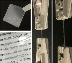
An ion gel membrane composed of [EMIM][C(CN)3] and Pebax 1657 was successfully prepared. An example of a prepared ion gel membrane is shown in Fig. 2. The ion gel membrane exhibited sufficient mechanical strength for manual manipulation. In addition, it was transparent, indicating that the Pebax 1657 network was homogeneously developed without significant aggregation. Furthermore, the ion gel membrane surface was not wet. This indicated that no [Emim][C(CN)3] leaked from the ion gel membrane because of the high compatibility of the PEO block with [Emim][C(CN)3]. Thus, it was suggested that the polyamide and PEO blocks in Pebax 1657 provided the desired mechanical strength and [Emim][C(CN)3]-holding properties.3.2 Mechanical strength of the ion gel membrane
To evaluate the effect of the IL content on the mechanical strength of the Pebax ion gel membrane, we prepared an ion gel membrane with different [Emim][C(CN)3] contents and measured the mechanical properties using a uniaxial tensile test. In this experiment, the [Emim][C(CN)3] content of the ion gel membrane changed from 60 to 82.5 wt%. The uniaxial stress–strain curves of the ion gel membranes are shown in Fig. 3. As shown in Fig. 3, the mechanical strength of the ion gel membrane decreased with increasing [Emim][C(CN)3] content. To evaluate the mechanical properties of the ion gel membrane in detail, Young's modulus, fracture strain, fracture stress, and fracture energy of the ion gel membranes were determined from each stress–strain curve in Fig. 3 and summarized in Fig. 4(a), (b), (c) and (d), respectively. In these figures, the mechanical properties of ion gels composed of [Emim][C(CN)3] and a semicrystalline poly(vinylidene fluoride-co-hexafluoropropylen (PVDF-HFP)) network, which is the polymer network used to make tough ion gel membranes containing less CO2 permeable [Emim][Tf2N] in our previous studies,35,36 are plotted for comparison. In addition, the mechanical properties of some tough ion gels reported elsewhere32,38,39 were also plotted. From the comparison, it can be seen that the fracture energy of the developed ion gel membrane with the Pebax 1657 network was much higher than that of the ion gel membrane with the PVDF-HFP network, and the mechanical properties of the developed ion gel, except for the fracture strain, were comparable to those of previously reported tough ion gels. Thus, it can be said that the developed Pebax ion gel is a kind of tough ion gel. In addition, it is worth mentioning that the IL contained in the developed ion gel membrane was [Emim][C(CN)3] which is much more CO2-philic than the ILs of the previously developed tough ion gels. Therefore, tough Pebax ion gels are preferable for high-performance CO2 separation membranes.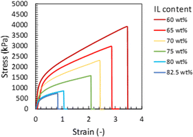 | ||
| Fig. 3 Tensile stress–strain curves of the developed Pebax ion gel with different contents of [Emim][C(CN)3]. | ||
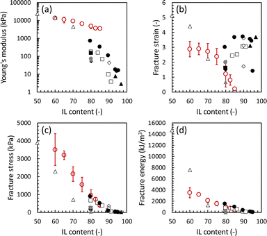 | ||
| Fig. 4 Mechanical properties of the developed Pebax ion gels with different [Emim][C(CN)3] content. Red ○: Pebax ion gel (This work), Δ: ion gel composed of PVDF-HFP and [Emim][C(CN)3] (this work), □: ion gel composed of PVDF-HFP/PDMAAm IPN and [Emim][Tf2N],35 ◊: ion gel composed of triblock copolymer network and [Bmim][Tf2N],38 ●: inorganic/organic double-network ion gel containing [Bmim][Tf2N],32 ▲: ion gel with tetra-PEG network and [Emim][Tf2N],39 ■: ion gel composed of PVDF-HFP/PDMAAm IPN and [Emim][B(CN)4],36 ♦: ion gel composed of PVDF-HFP/PMA IPN and [Emim][B(CN)4],36 ●: ion gel composed of PVDF-HFP/PEA IPN and [Emim][B(CN)4],36 and ▲ ion gel composed of PVDF-HFP/PNIPAM IPN and [Emim][B(CN)4].36 | ||
The toughening mechanism of the Pebax 1657 ion gel was investigated and discussed. Because Pebax 1657 is a block copolymer composed of an IL-philic PEO block and a polyamide block with poor compatibility with the IL, the polyamide block can effectively aggregate to form a semicrystalline structure. It has been reported that the semicrystalline structure of a gel network can dissipate loaded energy when a force is applied to the gel.35,36 Thus, it was considered that the developed ion gel had high mechanical strength because of the formation of a semi-crystalline structure of the polyamide block in the Pebax 1657 network and the dissipation of the applied energy by the decomposition of the semi-crystalline structure of the network.
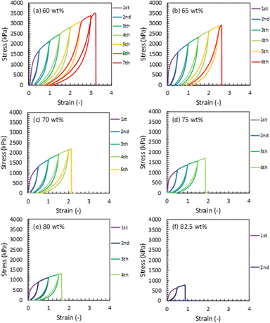
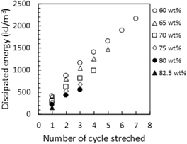
XRD measurements were conducted on ion gels with various [Emim][C(CN)3]/Pebax 1657 compositions. In Fig. 5(a), the XRD patterns of the ion gels and those of PEO and nylon 6 (polyamide), which are components of Pebax 1657, were used as references to identify the specific peaks of the ion gels. The XRD patterns of the PEO and polyamide are shown in Fig. 5(b). The XRD pattern of [EMIM][C(CN)3] is shown in Fig. 5(c). If the PEO and polyamide blocks in Pebax 1657 form a crystalline structure in the ion gel, their peaks would appear at both 19° and 23° and 20° and 24°, respectively (Fig. 5(b)). However, as shown in the XRD patterns of the ion gels, although peaks are observed at 20° and 24°, no clear peaks are observed at 19° or 23° (Fig. 5(a)). This indicated that the polyamide block formed a semi-crystalline structure in [Emim][C(CN)3], whereas the PEO block did not form any crystalline structure. As expected, because polyamide has poor compatibility with [Emim][C(CN)3], it aggregates and forms a semi-crystalline structure in the ion gel. However, owing to the good compatibility of PEO with the IL, the PEO segment cannot form a crystalline structure. To confirm the retention of the semi-crystalline structure of the polyamide block and the destruction of the semi-crystalline structure of PEO block in the Pebax ion gel membrane, we measured the FT-IR spectra of the Pebax 1657 membrane without [Emim][C(CN)3] and the Pebax ion gel membranes with different [Emim][C(CN)3] contents. The results are shown in Fig. S1 in the ESI.† In Fig. S1(d),† it was clearly found that the C–O–C stretching vibration peak of the PEO chain of Pebax 1657 is red-shifted from 1094 cm−1 to 1087 cm−1. This red shift would be due to the interaction of [Emim][C(CN)3] with the O atom of the ether bond of the PEO group, resulting in a decrease in the electron density on the O atom and an increase in the C–O–C bond length. In other words, it is considered that [Emim][C(CN)3] solvates to the ether bond of the PEO group. On the other hand, as shown in Fig. S1(b),† the peak at around 2860 cm−1, which is assigned to the stretching vibration of the ethylene chain, was blue-shifted to 2870 cm−1 in the ion gel. The ethylene chains of the PEO block in the Pebax 1657 membrane without [Emim][C(CN)3] form a semi-crystalline structure. Thus, it can be considered that the thermal motion of the crystallized PEO block is low. However, when [Emim][C(CN)3] solvated with the ether bonds of PEO block in the ion gel, the semi-crystalline structure of the PEO blocks destroyed. As a result, the thermal motion of the ethylene chains increased in the ion gel. Therefore, the stretching frequency of the ethylene chain increases, and the corresponding peak was shifted to a higher wave number. Regarding the polyamide block, as indicated in Fig. S1(c),† the wavenumbers of the peaks assigned to the C![[double bond, length as m-dash]](https://www.rsc.org/images/entities/char_e001.gif) O and NH groups of the Pebax 1657 network in Pebax ion gel were not shifted from those of the Pebax 1657 membrane without [Emim][C(CN)3]. These results indicated that [Emim][C(CN)3] strongly interacted with PEO chains but not with polyamide. In other words, the results of the FT-IR analysis support the XRD results suggesting that the semi-crystalline network structure of the polyamide blocks is maintained in the ion gels. From these results, it was suggested that the semi-crystalline structure of the polyamide block in Pebax 1657 crosslinked the gel network and dissipated the loaded energy when a force was applied to the ion gel. To confirm the energy-dissipation-based toughening mechanism of the Pebax ion gel, we conducted cyclic stress–strain measurements on ion gels with different [Emim][C(CN)3] contents. As indicated in Fig. 6, the cyclic stress–strain curves show a clear hysteresis loop. In addition, as shown in Fig. 7, the dissipated energy at a certain strain increased with decreased [Emim][C(CN)3] content. In other words, the higher the composition of the Pebax 1657 network, the greater is the energy dissipation. This trend indicated that the Pebax 1657 network contributed to energy dissipation. As mentioned above, because of the poor compatibility of the polyamide in Pebax 1657 with [Emim][C(CN)3], the polyamide block in Pebax 1657 formed a semi-crystalline structure in the ion gel. It was reported that a semi-crystalline polymer (polyvinyl alcohol) forms a semi-crystalline structure in a hydrogel, dissipates the loaded energy, and toughens the hydrogel in accordance with energy dissipation mechanism.40 Similarly, in the case of the Pebax ion gel system, the semi-crystalline structure of the polyamide block may also be able to dissipate the applied energy. Thus, it is strongly suggested that the destruction of the semi-crystalline structure of the polyamide block of Pebax 1657 contributes to the dissipation of the loaded energy and toughens the ion gel. The schematic illustration of the speculated gel network structure and toughening mechanism of Pebax ion gel are presented in Fig. S2.†
O and NH groups of the Pebax 1657 network in Pebax ion gel were not shifted from those of the Pebax 1657 membrane without [Emim][C(CN)3]. These results indicated that [Emim][C(CN)3] strongly interacted with PEO chains but not with polyamide. In other words, the results of the FT-IR analysis support the XRD results suggesting that the semi-crystalline network structure of the polyamide blocks is maintained in the ion gels. From these results, it was suggested that the semi-crystalline structure of the polyamide block in Pebax 1657 crosslinked the gel network and dissipated the loaded energy when a force was applied to the ion gel. To confirm the energy-dissipation-based toughening mechanism of the Pebax ion gel, we conducted cyclic stress–strain measurements on ion gels with different [Emim][C(CN)3] contents. As indicated in Fig. 6, the cyclic stress–strain curves show a clear hysteresis loop. In addition, as shown in Fig. 7, the dissipated energy at a certain strain increased with decreased [Emim][C(CN)3] content. In other words, the higher the composition of the Pebax 1657 network, the greater is the energy dissipation. This trend indicated that the Pebax 1657 network contributed to energy dissipation. As mentioned above, because of the poor compatibility of the polyamide in Pebax 1657 with [Emim][C(CN)3], the polyamide block in Pebax 1657 formed a semi-crystalline structure in the ion gel. It was reported that a semi-crystalline polymer (polyvinyl alcohol) forms a semi-crystalline structure in a hydrogel, dissipates the loaded energy, and toughens the hydrogel in accordance with energy dissipation mechanism.40 Similarly, in the case of the Pebax ion gel system, the semi-crystalline structure of the polyamide block may also be able to dissipate the applied energy. Thus, it is strongly suggested that the destruction of the semi-crystalline structure of the polyamide block of Pebax 1657 contributes to the dissipation of the loaded energy and toughens the ion gel. The schematic illustration of the speculated gel network structure and toughening mechanism of Pebax ion gel are presented in Fig. S2.†
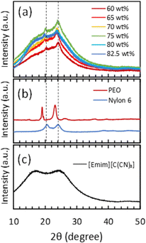 | ||
| Fig. 5 XRD patterns of (a) Pebax ion gels with different [Emim][C(CN)3] contents, (b) polyethylene oxide and Nylon 6, which are the components of Pebax 1657, and (c) [Emim][C(CN)3]. | ||
3.3 IL holding property of the Pebax ion gel membrane
As expected, Pebax 1657 has a positive effect not only on the mechanical strength but also on the IL-holding properties of the ion gel containing [Emim][C(CN)3]. In other words, in addition to the positive contribution of the semicrystalline polyamide segment of Pebax 1657 to the high mechanical strength of the ion gels, the PEO segment of Pebax 1675, which has a high affinity for [Emim][C(CN)3] could have a positive effect on the [Emim][C(CN)3] retention of the ion gel.The relationship between the IL-holding property and the compatibility of the gel network with the IL in the ion gel was evaluated by comparing the IL retention of several ion gels composed of different IL/polymer network pairs. As an example of an ion gel composed of a less compatible IL/polymer network pair, the ion gel consisting of a semi-crystalline PVDF-HFP network and [Emim][C(CN)3] had very poor [Emim][C(CN)3] holding properties. As another example, we previously reported35 that an ion gel composed of a less compatible [Emim][B(CN)4] and a PVDF-HFP network had very poor IL holding properties. For the ion gel composed of [Emim][B(CN)4] and the PVDF-HFP network, the IL holding properties were improved by interpenetrating an IL-philic polymer network with a semi-crystalline PVDF-HFP network.35 Although the interpenetration of an IL-philic polymer network with a semi-crystalline polymer network is a simple and effective way to improve the IL-holding property of an ion gel, the interpenetration of another polymer network usually significantly decreases the mechanical strength of the ion gel.35,36 The developed ion gel, composed of [Emim][C(CN)3] and the Pebax 1657 network, showed good mechanical strength and IL holding properties. Fig. 8 shows the IL leakage of the developed ion gels with various [EMIM][C(CN)3] contents and compressive pressures. As shown in this figure, the IL leakage from the ion gel composed of 80 wt% [Emim][C(CN)3] and 20 wt% Pebax 1657 at a compressive pressure of 1 MPa was less than 4%. Thus, the IL-holding property of the developed ion gel was equal to or better than that of a previously developed ion gel with an interpenetrating polymer network composed of PVDF-HFP and another IL-philic polymer.36 Favorable IL holding properties were realized because of the PEO block of Pebax 1657, which has good compatibility with [Emim][C(CN)3]. Thus, from the above-mentioned characterization results of the ion gels, it was concluded that a block copolymer consisting of a semi-crystalline block with poor compatibility with the IL and an IL-philic block is useful for fabricating an ion gel membrane with both high mechanical strength and good IL-holding properties without adding another CO2-philic polymer network.
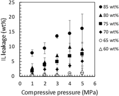 | ||
| Fig. 8 Leakage of [Emim][C(CN)3] from the Pebax ion gels with different [Emim][C(CN)3] contents under various compressive pressures. | ||
3.4 CO2 separation performance of the Pebax ion gel membrane
The CO2 permeability and CO2/N2 permselectivity of the developed Pebax 1657 ion gel membranes with various [Emim][C(CN)3] contents are shown in Fig. 9. These figures also show the performances of ion gel membranes with different ILs for comparison. The CO2 permeability of the developed ion gel membrane was between those of ion gel membranes with imidazolium-based ILs containing B(CN)4− and Tf2N− anions. The order of CO2 permeability was determined by the properties of the IL in the ion gel membranes, such as CO2 solubility and viscosity. As shown in Table 2, due to the low Henry's law constant for CO2 absorption and low viscosity of [Emim][B(CN)4], the ion gel membrane containing [Emim][B(CN)4] had the highest CO2 permeability. In contrast, because [Emim][C(CN)3] has a relatively high Henry's law constant but low viscosity, the CO2 permeability of the developed ion gel membrane containing [Emim][C(CN)3] was second only to that containing [Emim][B(CN)4]. The ion gel membranes with [Emim][Tf2N] and [Bmim][Tf2N] showed lower CO2 permeabilities because of their high viscosities. The CO2/N2 permselectivity of the ion gel membranes containing [Emim][B(CN)4] and [Emim][C(CN)3] was almost the same and much higher than those of [Emim][Tf2N] and [Bmim][Tf2N] (Fig. 9(b)).35,36,46 The CO2 solubility of ILs is strongly affected by the type of anion, and anions with cyano groups exhibit high CO2/N2 solubility selectivity.41,47,48 Thus, the higher CO2/N2 permselectivity of the ion gel membranes containing [Emim][B(CN)4] and [Emim][C(CN)3] could be due to the higher CO2/N2 solubility selectivity of the ILs with cyano-based anions49 than that of the ILs with Tf2N anions.50 From these results, it can be confirmed that the selective CO2 permeation of tough ion gel membranes with a high IL content is mainly determined by the properties of the ILs in the gel membrane. To the best of our knowledge, [Emim][C(CN)3] is the second-best IL for CO2 separation owing to its high CO2 solubility, high CO2/N2 solubility selectivity, and low viscosity.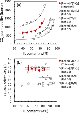 | ||
| Fig. 9 CO2 separation properties of the Pebax ion gel membrane with various [Emim][C(CN)3] content. Effect of [Emim][C(CN)3] content on (a) CO2 permeability and (b) CO2/N2 permselectivity. | ||
The CO2 permeability and CO2/N2 permselectivity of the developed Pebax 1657 ion gel membrane were compared with those of previously developed IL-based CO2 separation membranes and the upper bound of a polymeric CO2 separation membrane.51 As shown in Fig. 10, the CO2 separation performance of the Pebax 1657 ion gel membrane was on the Robeson upper limit of 2008, even though the [Emim][C(CN)3] content in the ion gel membrane was 60 wt%. Regarding the fabrication of a thin-film composite membrane with an ion gel-based selective layer, a thin ion gel layer with a lower IL content can be prepared more easily than one with a high IL content.
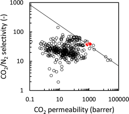 | ||
| Fig. 10 Relationship between CO2/N2 permselectivity and CO2 permeability of IL-based CO2 separation membranes. Open circles: previously reported IL-based CO2 separation membranes, red diamond: Pebax ion gel membranes with different [Emim][C(CN)3] contents (this work), and solid line: Robeson upper bound 2008.51 | ||
Therefore, the Pebax 1657 ion gel membrane with the IL content ranging from 60 wt% to 82.5 wt% prepared in this study could be useful to develop a thin film composite membrane with a thickness of such as 1 μm showing more than 1000 GPU of the CO2 permeance and approximately 40 of the CO2/N2 permselectivity.
Considering the practical application, the feasible post-combustion CO2 capture from an exhausted gas of a coal-fired power plant could be realized using a CO2 separation membrane with the CO2 permeation performances of at least 1000 GPU of the CO2 permeance and more than 20 of the CO2/N2 permselectivity for CO2/N2 mixture at an elevated temperature at 50 °C.15 Thus, the CO2 permeation performance of a Pebax 1657 ion gel membrane with 80 wt% [Emim][C(CN)3] was examined at various temperatures. Before the gas permeation test, because the Pebax ion gel developed in this study was made of a physically crosslinked gel network and would become a sol state at elevated temperatures, the thermal stabilities of the Pebax ion gel membranes with various [Emim][C(CN)3] contents were evaluated from the viscoelastic properties of the ion gels at elevated temperatures. As shown in Fig. 11(a), even though the IL content was 82.5 wt%, the sol–gel transition temperature of the Pebax ion gel membrane was higher than 140 °C. Therefore, it was confirmed that the Pebax ion gel membrane has sufficient thermal stability for post-combustion CO2 capture applications. Regarding the CO2 separation performance, the CO2 permeability and CO2/N2 permselectivity of the Pebax 1657 ion gel membrane were evaluated. As shown in Fig. 11(b), the Pebax ion gel membrane's CO2 permeability and CO2/N2 permselectivity increased and decreased, respectively, with increasing temperature. The increase in CO2 permeability was due to an increase in the diffusivity of CO2 in [Emim][C(CN)3] of the Pebax 1657 ion gel membrane. The increase in diffusivity resulted from a decrease in the viscosity of [Emim][C(CN)3] at elevated temperatures. In contrast, the decrease in CO2/N2 permselectivity with increasing temperature is due to the more substantial effect of temperature on N2 solubility than CO2 solubility.36 Due to the high CO2/N2 solubility selectivity of [Emim][C(CN)3], the Pebax 1657 ion gel membrane showed 29 of the CO2/N2 permselectivity at 50 °C. Thus, the Pebax 1657 ion gel membrane can be used to capture CO2 from an exhaust gas with high temperatures.
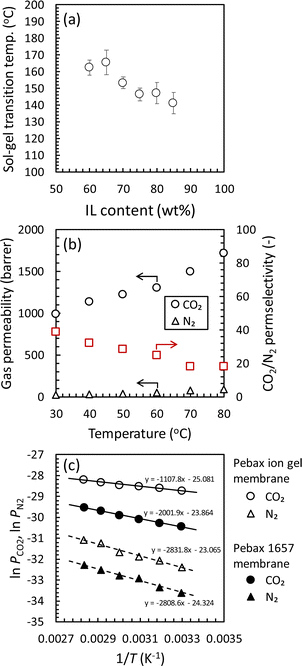 | ||
| Fig. 11 Effect of temperature on (a) sol–gel transition of the Pebax ion gels with various [Emim][C(CN)3] contents and (b) CO2 and N2 permeabilities and CO2/N2 permselectivity of the Pebax ion gel membrane with 80 wt% of [Emim][C(CN)3]. (c) Plots based on eqn (5) for the CO2 and N2 permeation through the Pebax ion gel membrane with 80 wt% of [Emim][C(CN)3] and the Pebax 1657 membrane with no ionic liquid. | ||
To consider the effect of temperature more deeply, the temperature dependence of the CO2 and N2 permeation through the Pebax ion gel membrane were compared with the Pebax 1657 membrane without [Emim][C(CN)3], and the thermodynamics was evaluated. As shown in Fig. S3,† both of the CO2 and N2 permeabilities of the Pebax ion gel membrane was higher than those of the pure Pebax 1657 membrane in whole of the temperature range investigated in this study. The higher gas permeability of the Pebax ion gel membrane is due to the high diffusivity of solute in the gel membrane. In addition, as indicated in Fig. S3,† the CO2/N2 permselectivity of the Pebax ion gel membrane is higher than that of the Pebax 1657 membrane at the temperature lower than 60 °C. The high CO2/N2 permselectivity at low temperature means that the high CO2 solubility of [Emim][C(CN)3] contributes to enhance the CO2 permeability. To discuss the difference of the temperature dependences of the CO2 permeabilities of the Pebax ion gel membrane and the Pebax 1657 membrane, we analyzed the temperature dependences. Because the permeation of CO2 and N2 through the Pebax ion gel membrane containing [Emim][C(CN)3] is according to solution-diffusion mechanism, the permeability, P, can be expressed by the product of the diffusion coefficient, D, and solubility coefficient, S, of CO2 and N2 in the ion gel.
| P = D·S | (2) |
Additionally, D and S are dependent on temperature according to Arrhenius relationship and van't Hoff relationship, respectively.
 | (3) |
 | (4) |
 | (5) |
The plots based on eqn (5) are shown in Fig. 11(c). From the slope of the straight lines shown in Fig. 11(c), the ED + ΔHs for CO2 and N2 permeation through the Pebax ion gel membrane and Pebax 1657 membrane were determined and listed in Table 3.
| Pebax ion gel membrane | Pebax 1657 membrane | |||
|---|---|---|---|---|
| CO2 | N2 | CO2 | N2 | |
| ED + ΔHs (kJ mol−1) | 9.2 | 23.6 | 16.6 | 23.4 |
As indicated in Table 3, the determined ED + ΔHs for N2 permeation through the Pebax ion gel membrane and Pebax 1657 membrane were almost the same. Thus, for the gases with quite small interaction with [Emim][C(CN)3] and Pebax 1657, it was suggested that energy barrier for the gases to permeate through Pebax ion gel membrane and Pebax 1657 membrane were also almost the same. On the other hand, for both of the membranes, the ED + ΔHs for CO2 permeation was smaller than that for N2 permeation. This is because the CO2 sorption is more exothermic than N2 sorption, and the system after CO2 sorption is more stable than that after N2 sorption. In addition, comparing the ED + ΔHs for CO2 permeation, the ED + ΔHs for CO2 permeation through the Pebax ion gel membrane was much lower than that through the Pebax 1657 membrane. Therefore, due to the strong interaction between [Emim][C(CN)3] and CO2, the Pebax ion gel membrane containing [Emim][C(CN)3] has high CO2 permeability and high CO2/N2 permselectivity at low temperature because of the strong interaction between CO2 and [Emim][C(CN)3].
In addition to temperature, the effect of humidity on CO2 separation performance is also important for post-commissioned CO2 capture applications because CO2 is usually captured from humid exhaust gas after desulfurization. Thus, the effect of relative humidity on the CO2 permeation property of the Pebax ion gel membrane containing 80 wt% of [Emim][C(CN)3] was evaluated at 50 °C. The results are presented in Fig. 12. The CO2 permeability increased with increasing relative humidity, and the CO2 permeability and CO2/N2 permselectivity became 1677 barrer and 37, respectively, at 75% of the relative humidity at 50 °C. The increase in CO2 permeability with increasing relative humidity was due to a decrease in the viscosity of [Emim][C(CN)3] in the Pebax ion gel membrane. Generally, the CO2 permeability and CO2/N2 permselectivity of polymeric membranes decrease or remain constant with an increase in relative humidity.52–57 Therefore, the increased CO2 permeability and CO2/N2 permselectivity with increasing relative humidity is a specific property of Pebax ion gel membranes. This property is preferable for CO2 capture from humid exhaust gases from a coal-fired power plant.
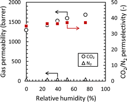 | ||
| Fig. 12 Effect of relative humidity on the CO2 and N2 permeabilities and CO2/N2 permselectivity of the Pebax ion gel membrane with 80 wt% of [Emim][C(CN)3] at 50 °C. | ||
4 Conclusions
A tough ion gel membrane containing a CO2-philic IL was fabricated using a diblock copolymer consisting of semi-crystalline polymer chain blocks and IL-philic polymer chain blocks. As the diblock copolymer, Pebax 1657, consisting of polyamide and PEO blocks, was used to prepare an ion gel membrane containing [Emim][C(CN)3]. It was confirmed that the polyamide block in Pebax 1657 formed a semicrystalline structure in [Emim][C(CN)3] and dissipated the loaded energy to toughen the ion gel membrane. In contrast, the PEO block in Pebax 1657 helped to retain [Emim][C(CN)3] in the ion gel. Due to the high affinity of [Emim][C(CN)3] for CO2, the ion gel membrane had a high CO2 permeability of over 1230 barrer and a high CO2/N2 permeation selectivity of 29 even at 50 °C. The CO2 permeability and CO2/N2 permselectivity increased with increasing humidity and were 1677 barrer and 37, respectively, at 50 °C and 75% relative humidity. The high performance under humid conditions at elevated temperatures indicates that the Pebax ion gel membrane has good prospects as a CO2 separation membrane for post-combustion CO2 capture from coal-fired power plants.Author contributions
JM, conceptualization, methodology, validation, formal analysis, investigation, and writing – original draft; EK, conceptualization, validation, writing – review & editing, and funding acquisition; AM, conceptualization and validation; KN, methodology and validation; TY, formal analysis and validation; HM, resources, supervision, writing – review & editing, and funding acquisition.Conflicts of interest
There are no conflicts to declare.Acknowledgements
This work was partially supported by KAKENHI (21H01691) of the Japan Society for the Promotion of Science (JSPS).Notes and references
- M. Z. Jacobson, Energy Environ. Sci., 2009, 2, 148–173 RSC.
- B. Li, Y. Duan, D. Luebke and B. Morreale, Appl. Energy, 2013, 102, 1439–1447 CrossRef CAS.
- C. Le Quéré, R. M. Andrew, P. Friedlingstein, S. Sitch, J. Hauck, J. Pongratz, P. A. Pickers, J. I. Korsbakken, G. P. Peters, J. G. Canadell, A. Arneth, V. K. Arora, L. Barbero, A. Bastos, L. Bopp, F. Chevallier, L. P. Chini, P. Ciais, S. C. Doney, T. Gkritzalis, D. S. Goll, I. Harris, V. Haverd, F. M. Hoffman, M. Hoppema, R. A. Houghton, G. Hurtt, T. Ilyina, A. K. Jain, T. Johannessen, C. D. Jones, E. Kato, R. F. Keeling, K. K. Goldewijk, P. Landschützer, N. Lefèvre, S. Lienert, Z. Liu, D. Lombardozzi, N. Metzl, D. R. Munro, J. E. M. S. Nabel, S. Nakaoka, C. Neill, A. Olsen, T. Ono, P. Patra, A. Peregon, W. Peters, P. Peylin, B. Pfeil, D. Pierrot, B. Poulter, G. Rehder, L. Resplandy, E. Robertson, M. Rocher, C. Rödenbeck, U. Schuster, J. Schwinger, R. Séférian, I. Skjelvan, T. Steinhoff, A. Sutton, P. P. Tans, H. Tian, B. Tilbrook, F. N. Tubiello, I. T. van der Laan-Luijkx, G. R. van der Werf, N. Viovy, A. P. Walker, A. J. Wiltshire, R. Wright, S. Zaehle and B. Zheng, Earth Syst. Sci. Data, 2018, 10, 2141–2194 CrossRef.
- D. Y. C. Leung, G. Caramanna and M. M. Maroto-Valer, Renewable Sustainable Energy Rev., 2014, 39, 426–443 CrossRef CAS.
- R. Ahmed, G. Liu, B. Yousaf, Q. Abbas, H. Ullah and M. U. Ali, J. Cleaner Prod., 2020, 242, 118409 CrossRef CAS.
- Z. Zhang, S.-Y. Pan, H. Li, J. Cai, A. G. Olabi, E. J. Anthony and V. Manovic, Renewable Sustainable Energy Rev., 2020, 125, 109799 CrossRef CAS.
- A. S. Bhown and B. C. Freeman, Environ. Sci. Technol., 2011, 45, 8624–8632 CrossRef CAS PubMed.
- Y. Takamura, S. Narita, J. Aoki and S. Uchida, Can. J. Chem. Eng., 2001, 79, 812–816 CrossRef CAS.
- A. M. Yousef, W. M. El-Maghlany, Y. A. Eldrainy and A. Attia, Energy, 2018, 156, 328–351 CrossRef CAS.
- R. W. Baker and B. T. Low, Macromolecules, 2014, 47, 6999–7013 CrossRef CAS.
- M. Li, X. Jiang and G. He, Front. Chem. Sci. Eng., 2014, 8, 233–239 CrossRef CAS.
- E. Favre, J. Membr. Sci., 2007, 294, 50–59 CrossRef CAS.
- R. W. Baker and K. Lokhandwala, Ind. Eng. Chem. Res., 2008, 47, 2109–2121 CrossRef CAS.
- R. Bounaceur, N. Lape, D. Roizard, C. Vallieres and E. Favre, Energy, 2006, 31, 2556–2570 CrossRef CAS.
- T. C. Merkel, H. Lin, X. Wei and R. Baker, J. Membr. Sci., 2010, 359, 126–139 CrossRef CAS.
- S. J. Kim, H. Jeon, D. J. Kim and J. H. Kim, ChemSusChem, 2015, 8, 3783–3792 CrossRef CAS PubMed.
- T. Hu, G. Dong, H. Li and V. Chen, J. Membr. Sci., 2014, 468, 107–117 CrossRef CAS.
- A. Nebipasagil, J. Park, O. R. Lane, B. J. Sundell, S. J. Mecham, B. D. Freeman, J. S. Riffle and J. E. McGrath, Polymer, 2017, 118, 256–267 CrossRef CAS.
- I. Taniguchi, N. Wada, K. Kinugasa and M. Higa, J. Membr. Sci., 2017, 535, 239–247 CrossRef CAS.
- L. A. Blancard, D. Hancu, E. J. Beckman and J. F. Brennecke, Nature, 1999, 399, 28–29 CrossRef CAS.
- E. Kamio, T. Yoshioka and H. Matsuyama, J. Chem. Eng. Jpn., 2023, 56, 2222000–2222001 CrossRef.
- E. Rynkowska, K. Fatyeyeva and W. Kujawski, Rev. Chem. Eng., 2018, 34, 341–363 CrossRef CAS.
- B. A. Voss, J. E. Bara, D. L. Gin and R. D. Noble, Chem. Mater., 2009, 21, 3027–3029 CrossRef CAS.
- P. T. Nguyen, B. A. Voss, E. F. Wiesenauer, D. L. Gin and R. D. Noble, Ind. Eng. Chem. Res., 2013, 52, 8812–8821 CrossRef CAS.
- R. M. Couto, T. Carvalho, L. A. Neves, R. M. Ruivo, P. Vidinha, A. Paiva, I. M. Coelhoso, S. Barreiros and P. C. Simoes, Sep. Purif. Technol., 2013, 106, 22–31 CrossRef CAS.
- A. B. Pereiro, L. C. Tome, S. Martinho, L. P. N. Rebelo and I. M. Marrucho, Ind. Eng. Chem. Res., 2013, 52, 4994–5001 CrossRef CAS.
- B. Lam, M. Wei, L. Zhu, S. Luo, R. Guo, A. Morisato, P. Alexandridis and H. Lin, Polymer, 2016, 89, 1–11 CrossRef CAS.
- A. R. Nabais, L. A. Neves and L. C. Tome, ACS Appl. Polym. Mater., 2022, 4, 3098–3119 CrossRef CAS.
- Y. Gu, E. L. Cussler and T. P. Lodge, J. Membr. Sci., 2012, 423–424, 20–26 CrossRef CAS.
- K. Fujii, T. Makino, K. Hashimoto, T. Sakai, M. Kanakubo and M. Shibayama, Chem. Lett., 2015, 44, 17 CrossRef.
- J. Zhang, E. Kamio, M. Kinoshita, A. Matsuoka, K. Nakagawa, T. Yoshioka and H. Matsuyama, Ind. Eng. Chem. Res., 2021, 60, 12698–12708 CrossRef CAS.
- E. Kamio, M. Minakata, Y. Iida, T. Yasui, A. Matsuoka and H. Matsuyama, Polym. J., 2021, 53, 137–147 CrossRef.
- J. C. Jansen, K. Friess, G. Clarizia, J. Schauer and P. Izak, Macromolecules, 2011, 44, 39–45 CrossRef CAS.
- J. M. Harner and D. A. Hoagland, J. Phys. Chem. B, 2010, 114, 3411–3418 CrossRef CAS PubMed.
- J. Zhang, E. Kamio, A. Matsuoka, K. Nakagawa, T. Yoshioka and H. Matsuyama, Ind. Eng. Chem. Res., 2022, 61, 4648–4658 CrossRef CAS.
- S. He, E. Kamio, J. Zhang, A. Matsuoka, K. Nakagawa, T. Yoshioka and H. Matsuyama, J. Membr. Sci., 2023, 685, 121912 CrossRef CAS.
- A. S. L. Gouveia, E. Bumenn, K. Rohtlaid, A. Michaud, T. M. Vieira, V. D. Alves, L. C. Tome, C. Plesse and I. M. Marrucho, Sep. Purif. Technol., 2021, 274, 118437 CrossRef CAS.
- Y. Gu, S. Zhang, L. Martinetti, K. H. Lee, L. D. McIntosh, C. D. Frisbie and T. P. Lodge, J. Am. Chem. Soc., 2013, 135, 9652–9655 CrossRef CAS PubMed.
- K. Fujii, H. Asai, T. Ueki, T. Sakai, S. Imaizumi, U.-i. Chung, M. Watanabe and M. Shibayama, Soft Matter, 2012, 8, 1756–1759 RSC.
- G. X. Chen, S. J. Tang, H. H. Yan, X. B. Zhu, H. M. Wang, L. Y. Ma, K. Mao, C. Y. Yang and J. B. Ran, Polymers, 2023, 15, 724 CrossRef CAS PubMed.
- K. Huang and H.-L. Peng, J. Chem. Eng. Data, 2017, 62, 4108–4116 CrossRef CAS.
- S. M. Mahurin, P. C. Hillesheim, J. S. Yeary, D.-e. Jiang and S. Dai, RSC Adv., 2012, 2, 11813–11819 RSC.
- D. Camper, C. Becker, C. Koval and R. Noble, Ind. Eng. Chem. Res., 2006, 45, 445–450 CrossRef CAS.
- M. Kanakubo, T. Makino, T. Taniguchi, T. Nokami and T. Itoh, ACS Sustainable Chem. Eng., 2016, 4, 525–535 CrossRef CAS.
- J. L. Anthony, J. L. Anderson, E. J. Maginn and J. F. Brennecke, J. Phys. Chem. B, 2005, 109, 6366–6374 CrossRef CAS PubMed.
- J. Zhang, E. Kamio, A. Matsuoka, K. Nakagawa, T. Yoshioka and H. Matsuyama, Ind. Eng. Chem. Res., 2021, 60, 12640–12649 CrossRef CAS.
- L. F. Zubeir, T. M. J. Nijssen, T. Spyriouni, J. Meuldijk, J.-R. Hill and M. C. Kroon, J. Chem. Eng. Data, 2016, 61, 4281–4295 CrossRef CAS.
- L. C. Tome, C. Florindo, C. S. R. Freire, L. P. N. Rebelo and I. M. Marrucho, Phys. Chem. Chem. Phys., 2014, 16, 17172–17182 RSC.
- J. E. Kim, H. J. Kim and J. S. Lim, Fluid Phase Equilib., 2014, 367, 151–158 CrossRef CAS.
- J. L. Anderson, J. K. Dixon and J. F. Brennecke, Acc. Chem. Res., 2007, 40, 1208–1216 CrossRef CAS PubMed.
- L. M. Robeson, J. Membr. Sci., 2008, 320, 390–400 CrossRef CAS.
- G. Q. Chen, C. A. Scholes, G. G. Qiao and S. E. Kentish, J. Membr. Sci., 2011, 379, 479–487 CrossRef CAS.
- C. A. Scholes, J. Jin, G. W. Stevens and S. E. Kentish, J. Polym. Sci., Part B: Polym. Phys., 2015, 53, 719–728 CrossRef CAS.
- E. Lasseuguette, M.-C. Ferrari and S. Brandani, Energy Procedia, 2014, 63, 194–201 CrossRef CAS.
- E. Lasseuguette, M. Carta, S. Brandani and M.-C. Ferrari, Int. J. Greenhouse Gas Control, 2016, 50, 93–99 CrossRef CAS.
- A. Fuoco, B. Satilmis, T. Uyar, M. Monteleone, E. Esposito, C. Muzzi, E. Tocci, M. Longo, M. P. De Santo, M. Lanc, K. Friess, O. Vopicka, P. Izak and J. C. Jansen, J. Membr. Sci., 2020, 594, 117460 CrossRef.
- C. A. Scholes, S. Kanehashi, G. W. Stevens and S. E. Kentish, Sep. Purif. Technol., 2015, 147, 203–209 CrossRef CAS.
Footnote |
| † Electronic supplementary information (ESI) available. See DOI: https://doi.org/10.1039/d3ra08730a |
| This journal is © The Royal Society of Chemistry 2024 |


