 Open Access Article
Preparation and application of alkali-activated cementitious materials in solidification/stabilization of chromite ore processing residue†
Pengyue Su‡
a,
Pan Zhao‡a,
Hao Wanga,
Kun Zhoua,
Yicheng Guoa,
Sha Liua,
Huicheng Lua,
Haiyu Chena,
Lanjun Zhanga,
Ziqiang Hee,
Ming Xia *abc and
Shujie Zhao*d
aSchool of Environmental and Chemical Engineering, Jiangsu Ocean University, Lianyungang, 222005, China. E-mail: xiaming@jou.edu.cn
bJiangsu Institute of Marine Resources Development, Jiangsu Ocean University, Lianyungang, 222005, China
cJiangsu Key Laboratory of Function Control Technology for Advanced Materials, Jiangsu Ocean University, Lianyungang, 222005, China
dSchool of Safety Science and Engineering, Anhui University of Science and Technology, Huainan, 232001, China. E-mail: zsj9506@163.com
eKey Laboratory of Electromechanical Equipment Security in Western Complex Environment for State Market Regulation, Chongqing Special Equipment Inspection and Research Institute, Chongqing, 401121, China
First published on 20th June 2024
Abstract
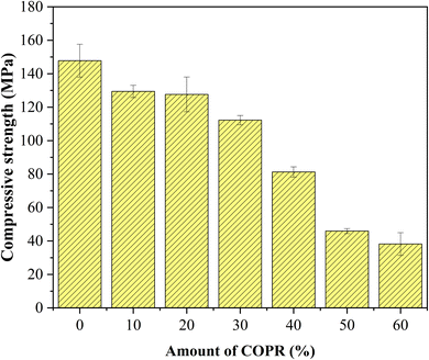
Chromite ore processing residue (COPR) is a typical hazardous waste, which contains Cr(VI) and poses a great threat to the ecological environment and human health. In this study, solidification/stabilization (S/S) of COPR was carried out by using blast furnace slag (BFS) and fly ash (FA) to prepare alkali-activated cementitious materials (AACM). The influence of different factors (water glass modulus, liquid–solid ratio, alkali–solid content and curing temperature) on compressive strength was investigated by single-factor experiment. Additionally, solidification effect of AACM was determined according to the compressive strength and the leaching concentration of chromium (Cr(VI) and total Cr). According to the optimal conditions of the single-factor experiment, the highest compressive strength of 147.6 MPa was obtained after using the water glass modulus 1.0, liquid–solid ratio 0.28, alkali–solid content 8%, curing temperature 45 °C. The COPR was solidified in the AACM sample having highest compressive strength. The solidified body still has a good mechanical property (38.2 MPa) with 60% addition COPR. According to leaching tests, the leaching of Cr(VI) and total Cr of solidified body with 50% COPR was far lower than the limit value, which met the purpose of construction and landfill disposal. X-ray diffraction (XRD) analysis, Fourier transform infrared spectroscopy (FTIR) and scanning electron microscopy (SEM) analysis proved that heavy metal chromium was solidified in AACM by physical and chemical means.
1. Introduction
Chromite ore processing residue (COPR) is a toxic and harmful waste residue generated in the process of producing chromium salts. COPR contains a significant amount of water-soluble and acid-soluble hexavalent chromium ions, constituting a substance that causes teratogenic, carcinogenic, and mutagenic effects, whose leaching toxicity far exceeds that of relatively stable trivalent chromium ions.1 Unreasonable stacking or irregular treatment of COPR will severely pollute soil and groundwater, posing a significant threat to human health. Therefore, it is necessary to carry out resource-based disposal of COPR.Currently, various methods have been used to handle hazardous wastes, such as thermal treatment technology,2–4 chemical neutralization and extraction separation technology,5–7 biological treatment technology8–10 and solidification/stabilization (S/S) technology.1,11 The technical advantages and disadvantages were shown in Table 1. The United States Environmental Protection Agency (USEPA) has highlighted that S/S is regarded as the best treatment technology due to its high efficiency in the treatment of hazardous waste.1,12,13
| Methods | Advantages | Disadvantages |
|---|---|---|
| Thermal treatment technology | Thorough treatment; volume reduction | High energy consumption; high equipment demands; air pollution |
| Chemical neutralization and extraction separation technology | Rapid and efficient; wide applicability | Secondary pollution; high cost; complex process |
| Biological treatment technology | Environmentally friendly; low cost; adaptable | Long treatment time; environmental dependency; limited range |
| Solidification/stabilization (S/S) technology | Long-term stability; simple operation; versatile materials | High cost of materials; large space consumption; long-term monitoring required |
In the early stages, ordinary Portland cement (OPC) was widely utilized to S/S hazardous waste due to its high compressive strength, but its high energy consumption and poor stability for chromium stabilization limit its application. In a bid to enhance cement properties and mitigate carbon emissions, French chemist Joseph Davidovits initially introduced the concept of geopolymers during 1979.14 This novel alkali-activated cementitious material (AACM) is primarily produced by combining general solid wastes abundant in Si, Al, and Ca (such as Fly Ash (FA), Blast Furnace Slag (BFS), metakaolin, etc.) with alkaline activators (Na2SiO3, NaOH, KOH, or K2SiO3) to initiate a hydration reaction, forming a hydrated aluminum silicate gel.15 Subsequently, it gradually solidifies through further hydration reaction and polycondensation, leading to the formation of the rigid structure.
Numerous researchers have observed the effective solidification of heavy metals through AACM. Xia et al. 2019 (ref. 13) had achieved successful heavy metal solidification of Cr, Cu, Zn, and Pb derived from lead and zinc smelting slag (LZSS) by creating composite AACM using BFS and FA. Zhang et al. 2020 (ref. 16) had employed LZSS as a primary material to produce AACM, achieving self-cementation solidification of its heavy metals in the current study. Similarly, Zhao et al. 2022 (ref. 17) had effectively solidified heavy metals, including Cr, As, and Pb, which present in lead smelting slag (LSS) by AACM, obtaining a relatively high compressive strength of 47.1 MPa. Xing and Wang 2023 (ref. 18) had solidified heavy metals from municipal solid waste incineration fly ash using AACM, and pointed out the augmentation of C–(A)–S–H gel content and structural modifications within the solidified body had fostered increased compressive strength. Reduced pore size had reinforced the physical encapsulation of heavy metals and had diminished their leaching toxicity over extended curing periods.
BFS is one kind of waste residue generated during the blast furnace ironmaking in steel mills, while FA is the residue recovered and extracted from the flue gas of coal-fired power plants. The preparation process of BFS-AACM (preparation of AACM using BFS) primarily involves the dissolution of Ca and Al participation to form a C–(A)–S–H type gel structure (CaO–Al2O3–SiO2–H2O).19,20 On the other hand, FA-AACM (preparation of AACM using FA) achieves strength development through the formation of a three-dimensional ‘N–A–S–H’ type gel (NaO2–Al2O3–SiO2–H2O).1,21 Typically, BFS-AACM tends to encounter issues such as poor workability, short setting time, and significant shrinkage. Similarly, FA-AACM also suffers from drawbacks like low reactivity.21,22 Existing studies have demonstrated that utilizing both BFS and FA for AACM production exhibits a synergistic effect, which could improve the mechanical properties and stability.1,23
The stability and mechanical properties of AACM are influenced by the dosage and composition of alkaline activating agents. Researchers investigated the impact of various factors on AACM strength. Chen et al. 2021 (ref. 24) analyzed the effects of alkali dosage (4–8%) and water glass modulus (0.5, 1.0, 1.5, 2.0) on the self-shrinkage ability of BFS-AACM. They noted that as the modulus increased, the self-shrinkage ability initially rose before declining. Additionally, an excess of silicate in the activator hindered internal water consumption, reducing the material's self-shrinkage ability. Likewise, the liquid–solid ratio for material preparation and the initial 24 h curing temperature also influenced the reaction. Muhammad et al. 2018 (ref. 25) discovered that water acted as the carrier of the alkaline activator, but higher water content diluted the alkali solution and generated larger pores, impacting curing strength. Zeng et al. 2022 (ref. 26) established that variations in the initial curing temperature affect the final compressive strength by influencing porosity.
Therefore, a composite alkali-activated cementitious materials (B–F-AACM) was prepared using BFS and FA for S/S of COPR. The single-factor experiment was conducted to investigate the impact of various factors on compressive strength, including water glass modulus, liquid–solid ratio, alkali-solid content, and curing temperature (24 hours prior). The mechanical strength and stability of the solidified body were evaluated through compressive strength test and leaching behavior analysis. Solidified body was characterized by the XRD, FTIR, and SEM techniques to further analyze the solidification mechanism.
2. Materials and methods
2.1 Materials
Respectively, the BFS and FA utilized in this experiment were brought from Ji Yuan steel factory and Da Tang power plant in Henan, China. While, the COPR was obtained from a chemical plant located in Chongqing, China. The analytical grade alkali activators were used in this study which were sodium silicate (Na2SiO3·3.3H2O) and sodium hydroxide (NaOH). Deionized water was utilized throughout all experiments conducted. XRF analysis was performed to determine the chemical composition of BFS, FA, and COPR. The results were presented in Table S1.† BFS primarily consisted of CaO, SiO2, and Al2O3, which accounted for 82.37% of the total components; whereas FA mainly comprised SiO2, Al2O3, and Fe2O3 components. COPR contained Fe2O3 (52.92%), Al2O3 (14.88%), MgO (10.55%), and Cr2O3 (10.53%) as its major constituents. Moreover, Fe in COPR was presented as Fe(III) according to the XPS spectra in Fig. S1(a).†2.2 Methods
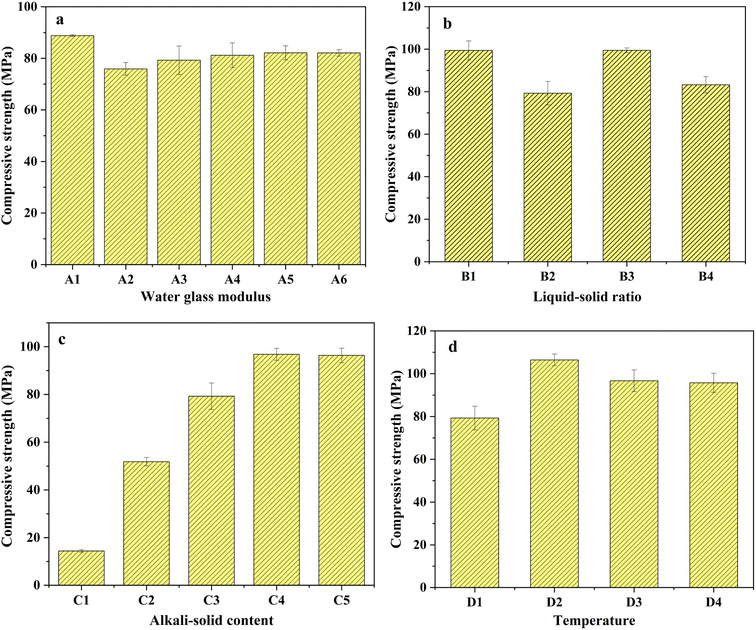
| ID | Water glass modulus | Liquid–solid ratio | Alkali–solid content (%) | Curing temperature (°C) |
|---|---|---|---|---|
| a Alkali–solid content: percentage of alkali–solid (Na2SiO3 and NaOH) in total solids; liquid–solid ratio: the ratio of water (deionized water and water in water glass) to total solids. | ||||
| A1 | 1.0 | 0.26 | 6 | 30 |
| A2 | 1.2 | 0.26 | 6 | 30 |
| A3 | 1.4 | 0.26 | 6 | 30 |
| A4 | 1.6 | 0.26 | 6 | 30 |
| A5 | 1.8 | 0.26 | 6 | 30 |
| A6 | 2.0 | 0.26 | 6 | 30 |
| B1 | 1.4 | 0.24 | 6 | 30 |
| B2 | 1.4 | 0.26 | 6 | 30 |
| B3 | 1.4 | 0.28 | 6 | 30 |
| B4 | 1.4 | 0.30 | 6 | 30 |
| C1 | 1.4 | 0.26 | 2 | 30 |
| C2 | 1.4 | 0.26 | 4 | 30 |
| C3 | 1.4 | 0.26 | 6 | 30 |
| C4 | 1.4 | 0.26 | 8 | 30 |
| C5 | 1.4 | 0.26 | 10 | 30 |
| D1 | 1.4 | 0.26 | 6 | 30 |
| D2 | 1.4 | 0.26 | 6 | 45 |
| D3 | 1.4 | 0.26 | 6 | 60 |
| D4 | 1.4 | 0.26 | 6 | 75 |
Prior to the experiment, BFS and FA were dried at 105 °C for 5 h and passed through a 200-mesh sieve to ensure uniform particle size distribution. The alkali activators (Na2SiO3 and NaOH) solution were mixed in certain proportion with BFS and FA for certain period of time. The resulting mixture was quickly stirred to form a colloidal substance before being poured into a cube mold measuring 20 mm × 20 mm × 20 mm. Vibration was applied for approximately 1 min to remove internal bubbles from the colloidal paste. Subsequently, the samples were kept at temperatures of 30 °C, 45 °C, 60 °C, and 75 °C for a duration of 24 h. After this initial curing period, the demolding process was carried out. Afterwards, the samples were left at room temperature for an additional 27 days. Finally, the optimum conditions were determined based on the highest compressive strength observed during the single-factor experimental analysis.
The COPR was solidified with the optimal combination of AACM (achieved through section 2.2.1). Various proportions (10%, 20%, 30%, 40%, 50% and 60%) of COPR, following a 5 hour drying process at 105 °C, were solidified into the composite alkali-activated cementitious materials, the COPR solidified bodies were named W10–W60, respectively. The amount of the alkaline activator used in Table S2.†
![[thin space (1/6-em)]](https://www.rsc.org/images/entities/char_2009.gif) :
:![[thin space (1/6-em)]](https://www.rsc.org/images/entities/char_2009.gif) 1, while maintaining a pH at 3.20 ± 0.05 and a liquid–solid ratio of 10
1, while maintaining a pH at 3.20 ± 0.05 and a liquid–solid ratio of 10![[thin space (1/6-em)]](https://www.rsc.org/images/entities/char_2009.gif) :
:![[thin space (1/6-em)]](https://www.rsc.org/images/entities/char_2009.gif) 1. After extraction, the filtrate obtained through filtration using microporous filter paper (size range: 0.6–0.8 μm) was preserved with HNO3 to maintain a pH below 2. TCLP was almost identical to the above method, except for using an acetic acid solution with a pH value of 2.88 ± 0.05 and a liquid–solid ratio of 20
1. After extraction, the filtrate obtained through filtration using microporous filter paper (size range: 0.6–0.8 μm) was preserved with HNO3 to maintain a pH below 2. TCLP was almost identical to the above method, except for using an acetic acid solution with a pH value of 2.88 ± 0.05 and a liquid–solid ratio of 20![[thin space (1/6-em)]](https://www.rsc.org/images/entities/char_2009.gif) :
:![[thin space (1/6-em)]](https://www.rsc.org/images/entities/char_2009.gif) 1 for extraction. The content of Cr(VI) was determined by spectrophotometer according to GB/T15555.4-1995 standard.29 The total chromium content was determined by flame atomic absorption spectrometer (FAAS) following HJ 749-2015 standard.30
1 for extraction. The content of Cr(VI) was determined by spectrophotometer according to GB/T15555.4-1995 standard.29 The total chromium content was determined by flame atomic absorption spectrometer (FAAS) following HJ 749-2015 standard.303. Results and discussion
3.1 Compressive strength influenced by single-factor experiment
The experiment investigated the impact of water glass modulus, liquid–solid ratio, alkali-solid content, and initial 24 h curing temperature on compressive strength, which were given below.3.2 Solidification/stabilization (S/S) of COPR
Based on the results of leaching tests and XPS. It was speculated that Cr(VI) was reduced by reducing substances (such as S2−) contained in BFS, resulting in an increase in the proportion of Cr(III) (eqn (1)).38 As the Cr(III) was transformed and accumulated, it reacted with other substances to form insoluble compounds under alkaline conditions (eqn (2)). After precipitation, these compounds are physically wrapped in the solidified body and exist in a stable form, thereby reducing the harm of Cr(VI) in COPR.
| 3S2− + 8CrO42− + 20H2O → 3SO42− + 8Cr3+ + 40OH− | (1) |
| Cr + 3OH− → Cr(OH)3 | (2) |
3.3 The X-ray diffraction (XRD) analysis
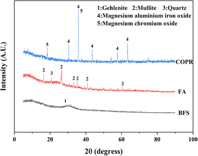
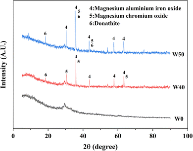
The XRD patterns of the raw materials (BFS, FA, and COPR) were presented in Fig. 5. BFS exhibited a broad and weak peak appearing around 2θ of 25°–35°, indicating its amorphous, and only has a minor presence of gehlenite phase (PDF# 35-0755). The primary phases observed in FA were mullite (PDF# 79-1276) and quartz (PDF# 82-0211). In COPR, magnesium aluminum iron oxide (MgFeAlO4, PDF# 11-0009) and magnesium chromium oxide (MgCr2O4, PDF# 77-0007) were the main phases detected, further suggesting a limited supply of alkali-activating substances from COPR. Fig. 6 illustrated the XRD patterns of the solidified bodies containing COPR. The strength of the amorphous hump in W0 (without COPR) increased and shifted to higher angles, signifying the formation of a new amorphous phase material. According to the study conducted by Huang et al. 2017 (ref. 1) and Puertas et al. 2011,20 it can be inferred that the formation of C–S–H gel structure occurred. The alkali activator facilitated the dissolution and recombination of Ca, Al, and Si substances abundant in BFS and FA, leading to the formation of C–S–H gel. Xia et al. 2020 (ref. 32) also discovered that the crystallinity of C–S–H phase was relatively low in AACM, with an increase in peak intensity over time. The XRD patterns of W40 and W50 exhibited remarkable similarities, both containing magnesium aluminum iron oxide and magnesium chromium oxide found in COPR. Additionally, a small amount of donathite ((Fe, Mg)(Cr, Fe)2O4, PDF# 22-0349) was present, indicating potential binding between chromium ions and silicates in an amorphous state.3.4 Fourier transform infrared spectroscopy (FTIR) analysis
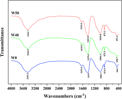
In order to gain a deeper understanding of the internal structural changes in solidified bodies and the solidification mechanism of heavy metal chromium after 28 days, FTIR was employed for analysis. As depicted in Fig. 7, the FTIR spectra of solidified bodies without COPR (W0) and those with COPR (W40, W50) exhibited similar characteristics. The absorption peak at 3400–3500 cm−1 corresponded to the OH stretching vibration.39 The absorption peak within the range of 1600–1650 cm−1 was attributed to the bending vibration of OH caused by H2O molecule adsorption on the solidified body,13,25,39 indicating the presence of water molecules in the solidified bodies. The antisymmetric stretching band at 1410–1430 cm−1 corresponded to O–C–O bond stretching vibrations,40 which was induced by CO2 participating in alkali activation processes leading to carbonate formation.13,35 The band near 1000 cm−1 was associated with antisymmetric stretching of Si–O–T bonds (T = tetrahedral Si or Al) in reaction products,40 with a shift towards higher wave numbers as COPR was added. This may be due to heavy metal chromium forming chemical bonds with aluminosilicate gel, resulting in a higher wave number absorption peak for Si–O–T bonding.41 Since increased COPR content reduced the Si/Al ratio among reactants. Therefore, there was a higher proportion of Si–O–Al compared to Si–O–Si bonds. Since Si–O–Al bonds were weaker than Si–O–Si bonds, network materials formed became more prone to fracture, thus exhibiting decreasing compressive strength trends.21The peak near 875 cm−1 related to antisymmetric stretching vibrations from AlO4− groups while that near 450 cm−1 pertained to bending vibrations from Si–O–Si and O–Si–O bonds.26,40 It can be observed from Fig. 7 that peaks within both ranges shift towards higher wave numbers. The shift to a higher wave number indicated that the presence of contaminant ions impacts the molecular structure of the solidified body.32 This could be attributed to either the substitution of Si by Cr in the gel structure or the influence of Cr on the C–S–H gel structure, altering the degree of gel polymerization.26 Consequently, compared to W40, there was an increase in leaching concentration of Cr(VI) and a decrease in compressive strength observed in W50.
4. Conclusions
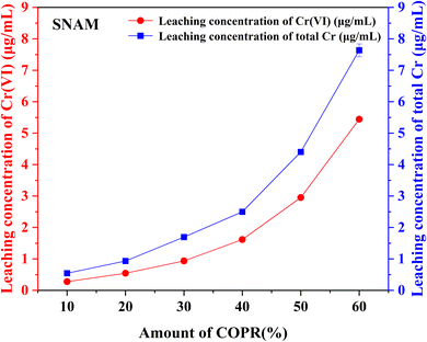
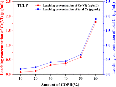
In this study, alkali activated BFS and FA were utilized for the preparation of AACM, and solidification/stabilization of COPR. A small amount of FA (5%) was added to BFS as a micro aggregate to create a denser internal structure within the solidified bodies. To optimize the formation condition for AACM, single-factor experiments were conducted with compressive strength as the evaluative index. Furthermore, the efficiency of the solidified body's stabilization/solidification process was assessed based on both its compressive strength and the leaching concentration of heavy metal Cr (Cr(VI) and total Cr). The physicochemical structure and microstructure analyses of the solidified bodies were performed using XRD, FTIR, and SEM techniques. Based on these analyses, the following conclusions were drawn.(1) With water glass modulus 1.0, liquid–solid ratio 0.28, alkali-solid content 8%, and curing temperature 45 °C, the maximum compressive strength reached 147.8 MPa for solidified samples (28 days). The addition of COPR led to a continuous decrease in the compressive strength of the solidified bodies. Even 60% addition COPR, W60 samples still exhibited favorable mechanical properties (38.2 MPa), which met the requirements for building material. The leaching results of COPR solidified bodies (≤50% COPR) in those methods (SNAM and TCLP) were below limit values, which demonstrated a significant immobilization effect on Cr(VI) and total Cr in the B–F-AACM solidified bodies compared to raw COPR. The results of leaching tests and XPS showed that the stability of Cr(VI) in the solidified body was due to the combined effects of physical and chemical processes. The chemical processes primarily include the reduction of Cr(VI) and the co-precipitation of Cr(III).
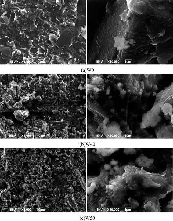
(2) The lower leaching concentration results, along with XRD, SEM, and FTIR analysis showed that the amorphous C–S–H gel structure was formed by alkali activation of BFS and FA. This gel structure exhibited high density and stability. While the addition of COPR disrupted the dense structure and caused a shift in the absorption peak observed in the FTIR spectra, indicating the presence of Cr influenced the molecular arrangement within the solidified body through chemical bonding. Furthermore, SEM images revealed that COPR could be physically immobilized within the gel structure of AACM. Therefore, the AACM can effectively handle COPR by employing both physical fixation and chemical reactions to securely immobilize chromium.
Abbreviations
| COPR | Chromite ore processing residue |
| BFS | Blast furnace slag |
| AACM | Alkali-activated cementitious materials |
| LZSS | Lead and zinc smelting slag |
| BFS-AACM | Preparation of AACM using BFS |
| C–(A)–S–H | CaO–Al2O3–SiO2–H2O |
| B–F-AACM | Preparation of the compose AACM using BFS and FA |
| TCLP | Toxicity characteristic leaching procedure |
| S/S | Solidification/stabilization |
| FA | Fly ash |
| OPC | Ordinary Portland cement |
| LSS | Lead smelting slag |
| FA-AACM | Preparation of AACM using FA |
| N–A–S–H | NaO2–Al2O3–SiO2–H2O |
| C–S–H | CaO–SiO2–H2O |
| SNAM | Sulfuric and nitric acid method |
Data availability
The date underlying this article are available in the article and its online ESI.†Author contributions
Pengyue Su: methodology, investigation, formal analysis, writing-original draft. Pan Zhao: writing-review & editing. Hao Wang: software, visualization. Kun Zhou: resources. Yicheng Guo: validation. Sha Liu: validation. Huicheng Lu: writing-review & editing. Haiyu Chen: funding acquisition. Lanjun Zhang: project administration. Ziqiang He: project administration. Ming Xia: conceptualization, project administration and funding acquisition. Shujie Zhao: supervision.Conflicts of interest
There are no conflicts of interest to declare.Acknowledgements
This study was supported by the Natural Science Foundation of Jiangsu Province (Grant No. BK20210926), National Natural Science Foundation of China (No. 52304196) and Jiangsu Ocean University Talent Introduction Start-up Fund (No. KQ21007). It was also funded by Innovation and Entrepreneurship Training Program for College Students (SY202111641637017, SZ202111641637004, SY202211641637014) and Postgraduate Research and Practice Innovation Program of Jiangsu Ocean University (KYCX2023-15). Supported by Open-end Funds of Jiangsu Key Laboratory of Function Control Technology for Advanced Materials, Jiangsu Ocean University (JSKLFCTAM202006) and Open-end Funds of Jiangsu Institute of Marine Resources Development (JSIMR202020).References
- X. Huang, R. Zhuang, F. Muhammad, L. Yu, Y. Shiau and D. Li, Chemosphere, 2017, 168, 300–308 CrossRef CAS PubMed.
- X. Chuai, R. Xiao, L. Chang, J. Wang, H. Yong, R. Jiang, T. Zhang, S. Tan, Y. Zhao, Z. Xiong and J. Zhang, J. Hazard. Mater., 2022, 431, 128656 CrossRef CAS.
- J. Ge, Y. Xiao, J. Kuang and X. Liu, Surf. Interfaces, 2022, 29, 101744 CrossRef CAS.
- S. S. Rath, P. Nayak, P. S. Mukherjee, G. Roy Chaudhury and B. K. Mishra, Waste Manage., 2012, 32, 575–583 CrossRef CAS PubMed.
- N. Li, C. Shi, Z. Zhang, D. Zhu, H.-J. Hwang, Y. Zhu and T. Sun, Cem. Concr. Compos., 2018, 93, 163–174 CrossRef CAS.
- Y. Li, J. Liang, Z. Yang, H. Wang and Y. Liu, Sci. Total Environ., 2019, 658, 315–323 CrossRef CAS PubMed.
- P. Zhang, L. Zeng, S. Zhang, C. Li and D. Li, Environ. Sci. Pollut. Res., 2022, 30, 29392–29406 CrossRef PubMed.
- M. He, F. Wu, G. Qu and X. Liu, Environ. Res., 2023, 238, 117149 CrossRef CAS PubMed.
- C. Jin, J. Yang, B. Chen, G. Qu, H. Li, F. Wu, X. Liu, Y. Liu, L. Kuang and J. Li, Environ. Res., 2023, 236, 116856 CrossRef CAS PubMed.
- A. B. Saralegui, V. Willson, N. Caracciolo, M. N. Piol and S. P. Boeykens, J. Environ. Manage., 2021, 289, 112398 CrossRef CAS PubMed.
- C. Shi and A. Fernández-Jiménez, J. Hazard. Mater., 2006, 137, 1656–1663 CrossRef CAS PubMed.
- I.-H. Yoon, D. H. Moon, K.-W. Kim, K.-Y. Lee, J.-H. Lee and M. G. Kim, J. Environ. Manage., 2010, 91, 2322–2328 CrossRef CAS PubMed.
- M. Xia, F. Muhammad, L. Zeng, S. Li, X. Huang, B. Jiao, Y. Shiau and D. Li, J. Cleaner Prod., 2019, 209, 1206–1215 CrossRef CAS.
- J. Davidovits, J. Therm. Anal., 1991, 37, 1633–1656 CrossRef CAS.
- L. Zhao, X. Ma, S. Song, P. You and H. Wu, Constr. Build. Mater., 2022, 319, 126091 CrossRef CAS.
- J. Zhang, Y. Ma, J. Zheng, J. Hu, J. Fu, Z. Zhang and H. Wang, Constr. Build. Mater., 2020, 261, 119940 CrossRef CAS.
- Z. Zhao, W. Liu, Y. Jiang, Y. Wan, R. Du and H. Li, J. Cleaner Prod., 2022, 359, 132134 CrossRef CAS.
- Y. Xing and B. Wang, J. Build. Eng., 2023, 78, 107573 CrossRef.
- I. Ismail, S. A. Bernal, J. L. Provis, R. San Nicolas, S. Hamdan and J. S. J. van Deventer, Cem. Concr. Compos., 2014, 45, 125–135 CrossRef CAS.
- F. Puertas, M. Palacios, H. Manzano, J. S. Dolado, A. Rico and J. Rodríguez, J. Eur. Ceram. Soc., 2011, 31, 2043–2056 CrossRef CAS.
- B. Sun, G. Ye and G. de Schutter, Constr. Build. Mater., 2022, 326, 126843 CrossRef CAS.
- A. Mehta, R. Siddique, T. Ozbakkaloglu, F. Uddin Ahmed Shaikh and R. Belarbi, Constr. Build. Mater., 2020, 257, 119548 CrossRef CAS.
- G. Fang, Q. Wang and M. Zhang, Composites, Part B, 2021, 224, 109221 CrossRef CAS.
- W. Chen, B. Li, J. Wang and N. Thom, Cem. Concr. Res., 2021, 141, 106322 CrossRef CAS.
- F. Muhammad, X. Huang, S. Li, M. Xia, M. Zhang, Q. Liu, M. A. Shehzad Hassan, B. Jiao, L. Yu and D. Li, J. Cleaner Prod., 2018, 188, 807–815 CrossRef CAS.
- L. Zeng, P. Zhang, J. Li, Q. Yu, Y. Zheng and D. Li, Ecotoxicol. Environ. Saf., 2022, 247, 114221 CrossRef CAS PubMed.
- CN-HJ, Solid Waste-Extraction Procedure for Leaching Toxicity-Sulphuric Acid and Nitric Acid Method (HJ/T 299-2007), 2007 Search PubMed.
- US Environmental Protection Agency, Toxicity Characteristic Leaching Procedure (Method 1311), 1992 Search PubMed.
- CN-GB, Solid Waste-Determination of Chromium(VI)-1,5-Diphenylcarbohydrazide Spectrophotometric Method (GB/T 15555. 4-1995), 1995 Search PubMed.
- CN-HJ, Solid Waste-Determination of Total Chromium-Flame Atomic Absorption Spectrometry (HJ 794-2015), 2015 Search PubMed.
- Z. Luo, T. Zhi, L. Liu, J. Mi, M. Zhang, C. Tian, Z. Si, X. Liu and Y. Mu, Constr. Build. Mater., 2022, 316, 125813 CrossRef CAS.
- M. Xia, F. Muhammad, S. Zhao, L. Yu, H. Lin, X. Huang, B. Jiao, Y. C. Shiau and D. Li, J. Environ. Manage., 2020, 265, 110350 CrossRef CAS PubMed.
- Z. Shi, C. Shi, S. Wan and Z. Zhang, Cem. Concr. Res., 2018, 111, 104–115 CrossRef CAS.
- H. Lahalle, V. Benavent, V. Trincal, T. Wattez, R. Bucher and M. Cyr, Constr. Build. Mater., 2021, 300, 124066 CrossRef CAS.
- L. Yu, L. Fang, P. Zhang, S. Zhao, B. Jiao and D. Li, Int. J. Environ. Res. Public Health, 2021, 18, 9960 CrossRef CAS PubMed.
- O. R. Ogirigbo and L. Black, Constr. Build. Mater., 2016, 126, 496–507 CrossRef CAS.
- R. Xie, R. Ge, Z. Li, G. Qu, Y. Zhang, Y. Xu, Y. Zeng and Z. Li, J. Environ. Manage., 2023, 325, 116469 CrossRef CAS PubMed.
- X. Huang, Research on Solidification/stabilization of Chromite Ore Processing Residue Using Composite Materials Based Geopolymer and its Enhanced Technology, PhD thesis, Chongqing University, 2018.
- C. Y. Heah, H. Kamarudin, A. M. Mustafa Al Bakri, M. Bnhussain, M. Luqman, I. Khairul Nizar, C. M. Ruzaidi and Y. M. Liew, Constr. Build. Mater., 2012, 35, 912–922 CrossRef.
- S. A. Bernal, J. L. Provis, V. Rose and R. Mejía de Gutierrez, Cem. Concr. Compos., 2011, 33, 46–54 CrossRef CAS.
- J. Liu, G. Xie, Z. Wang, Z. Li, X. Fan, H. Jin, W. Zhang, F. Xing and L. Tang, J. Environ. Manag., 2023, 341, 118053 CrossRef CAS PubMed.
Footnotes |
| † Electronic supplementary information (ESI) available. See DOI: https://doi.org/10.1039/d4ra01270d |
| ‡ These authors contributed equally to the work. |
| This journal is © The Royal Society of Chemistry 2024 |

