 Open Access Article
Experimental study on the mechanical and electrochemical properties of aqueous emulsifiable diphenylmethane diisocyanate-modified silicon–carbon composite electrodes
Dongliang Liu†
ab,
Detao Kong†ab,
Qinghua Yangab,
Yaolong He *abc and
Hongjiu Hu
 *ab
*ab
aShanghai Institute of Applied Mathematics and Mechanics, School of Mechanics and Engineering Science, Shanghai University, Shanghai 200072, China. E-mail: huhongjiu@shu.edu.cn; heyaolong@shu.edu.cn
bShanghai Key Laboratory of Mechanics in Energy Engineering, Shanghai 200072, China
cShanghai Frontier Science Center of Mechanoinformatics, Shanghai 200072, China
First published on 20th June 2024
Abstract
Aqueous emulsifiable diphenylmethane diisocyanate (EMDI) can form strong chemical bonds with aqueous adhesives due to the large number of isocyanate (–NCO) groups, which can enhance the mechanical performance of the adhesives. Currently, sodium carboxymethyl cellulose (CMC)–styrene butadiene rubber (SBR) emulsion aqueous bonding agents are widely used in the preparation of anode materials for lithium-ion batteries (LIBs). In this study, EMDI was added to a porous silicon–carbon composite electrode prepared from CMC–SBR, and the evolution of the mechanical properties of the electrode with the EMDI content was first investigated via quasi-static uniaxial tensile and interfacial strength tests. Subsequently, the effect of the EMDI content on the electrochemical properties of the electrodes was analysed by electrochemical impedance spectroscopy (EIS) and constant-current (CC) charge/discharge performance tests. Finally, material characterisation of the electrodes was carried out by Fourier transform infrared (FTIR) spectroscopy and specific surface area (Brunauer–Emmett–Teller (BET)) analysis. The results show that the addition of EMDI with a mass ratio of 10–20% to the CMC–SBR binder can enhance the mechanical performance of the active layer and the interfacial performance between the active layer and the current collector of the silicon–carbon composite electrode; simultaneously, EMDI can significantly reduce the electrochemical impedance of the electrode material and improve the capacity retention of the electrode. This study provides a new solution for modifying silicon–carbon composite electrodes and promotes the development of high-performance silicon–carbon electrodes.
1. Introduction
The theoretical specific capacity of silicon when fully lithiated (4200 mA h g−1) is 11 times greater than that of the current graphite anode (372 mA h g−1), and this material is widely regarded as an ideal anode material for the next generation of high-specific-capacity lithium-ion batteries (LIBs).1–5 However, silicon materials face challenges such as large volume expansion (>300%), poor electrical conductivity, and rapid capacity degradation during lithiation, which have hindered their large-scale commercial applications.6–10The formation of a silicon–carbon composite is one way to effectively solve the above problems, and the carbon material can not only improve the overall electrical conductivity of the active material but also act as a buffer layer to alleviate the volume expansion during the lithiation process of silicon.11–13 Based on the above advantages, silicon–carbon composites have become a hot topic of research in recent years. The performance of the adhesive is crucial for the battery capacity and cycle life, and the poor performance of current silicon–carbon composite electrode adhesives is not conducive to the cycling stability of the electrode during service. Therefore, some scholars have focused on the selection and modification of adhesives for silicon–carbon composite electrodes. For example, Cheng et al.14 prepared a new aqueous bonding agent, terpolymer (PtA) – polyvinyl alcohol (PVA), which is a combination of acrylic acid (AA), acrylamide (AM), 2-acrylamide-2-methylpropanesulfonic acid (AMPS), and PVA, and found that the PtA–PVA bonding agent could provide strong adhesion for the Si@C electrode, significantly improving its electrochemical performance. Dong et al.15 used a biopolymer composite binder combining poly(acrylic acid) (PAA) and silk fibroin (SF) for porous Si/C electrodes. The results indicated that the PAA/SF binder showed a robust gradient binding energy via chemical interactions between the carboxyl and amide groups and could effectively adapt to the volume changes of silicon during the electrode lithiation process, thus improving the electrochemical stability and coulombic efficiency of the Si/C electrode. Hong et al.16 synthesised a novel PAA and β-cyclodextrin polymer (β-CDp) adhesive and used it for in a silicon–carbon anode. The bonding agent could provide strong adhesion between the active layer and the current collector, which could effectively alleviate the volume changes during the lithiation process of the silicon–carbon negative electrode, thus improving the capacity and cycle life of the electrode. Xu et al.17 developed a conductive polymer bonding agent, polymerisation of polyaniline (PANi)@citric acid (CA), which was formed by PANi and CA. The results showed that the PANi@CA (PC) binder could accommodate the volume expansion of Si nanoparticles (SiNPs) upon lithiation and improve the cycling stability of the electrode. However, simple, efficient and cost-effective modification methods for silicon–carbon electrodes still require further exploration.
Isocyanates are widely used in coatings, adhesives, pharmaceuticals, agriculture and other industries due to their high stability, good water resistance and excellent chemical resistance.18 The unsaturated isocyanate group (–NCO) of isocyanates is very chemically active and can react with water, alcohols, amines, and other substances containing active hydrogen.19 Isocyanates have been added to battery materials to improve battery performance. For example, Shi et al.20 used fluorosulfonyl isocyanate (FI) as an electrolyte additive for graphite electrode modification. Since FI has a high reduction potential, it is reduced before the phosphate-based electrolyte and forms a solid-electrolyte interphase (SEI) film on the surface of the graphite active particles, thus reducing the graphite/electrolyte interfacial impedance and improving the rate performance of the battery. Hu et al.21 used 4,4′-diphenylmethane diisocyanate (MDI) to modify a poly(m-phenylene isophthalamide) (PMIA) diaphragm, which resulted in a substantial increase in both the fracture elongation and mechanical strength. Wang et al.22 used p-toluenesulfonyl isocyanate (PTSI) as an electrolyte additive for graphite electrode modification and found that 0.5 wt% PTSI could effectively improve the cycling capacity of graphite half-cells at high current densities. In summary, isocyanates can be used as additives to modify electrolytes or diaphragms to enhance battery electrochemical performance. However, there are relatively few studies on the modification of silicon–carbon composite electrode materials by isocyanates.
In this study, aqueous emulsifiable diphenylmethane diisocyanate (EMDI) was added as a crosslinking agent to the aqueous bonding system (sodium carboxymethyl cellulose–styrene-butadiene rubber (CMC–SBR)) of silicon–carbon composite electrodes, and the reaction between EMDI and the aqueous bonding system was utilised to modify silicon–carbon composite electrodes. First, the effects of the EMDI content on the mechanical performance of the silicon–carbon composite electrode active layer and the interfacial performance between the active layer and current collector were investigated via quasi-static tensile tests and interfacial bonding strength tests. Subsequently, the electrochemical performance of silicon–carbon composite electrodes with different EMDI contents was analysed via electrochemical impedance spectroscopy (EIS) and constant-current (CC) charge/discharge tests. Finally, material characterisation of the EMDI-modified silicon–carbon electrode was carried out via Fourier transform infrared (FTIR) spectroscopy and specific surface area (Brunauer–Emmett–Teller (BET)) analysis, and the EMDI crosslinking mechanism and modification mechanism were described in detail.
2. Experimental
2.1. Materials
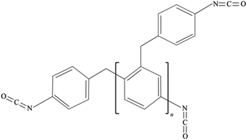
Carbon-coated silica oxide (SiOx/C, 99%, Kejing, Shenzhen), Super-P carbon black (CB, 99.9%, Kejing, Shenzhen), CMC (99%, Aladdin, Shanghai), SBR (50%, Zeon, Japan), and EMDI (Rubinate 9259, Huntsman, USA) which has a solid content of 100%, functionality of 2.7, and isocyanate content of 30.6%, were used. The chemical structure of EMDI is shown in Fig. 1. The CB, CMC, and SiOx/C active particles were placed in an 80 °C blower oven for 48 h for drying in advance to remove the residual moisture in the material.2.2. Sample preparation
![[thin space (1/6-em)]](https://www.rsc.org/images/entities/char_2009.gif) :
:![[thin space (1/6-em)]](https://www.rsc.org/images/entities/char_2009.gif) 1, placed in a planetary ball mill, and dry mixed for 1 h. Second, the binder solution described in Section 2.2.1 was slowly poured into the dry mixed active particle-conducting agent mixture, and a certain amount of deionised water was added to make the final solid content of the electrode slurry 30%, which was then mixed in a ball mill for 2 h. The slurry was placed in a vacuum drying oven for 15 min to remove the air bubbles in the slurry. Finally, the electrode slurry was coated on copper foil by an automatic coating machine, placed in a vacuum drying oven and dried at 80 °C for 24 h to obtain a dry and complete electrode sheet.
1, placed in a planetary ball mill, and dry mixed for 1 h. Second, the binder solution described in Section 2.2.1 was slowly poured into the dry mixed active particle-conducting agent mixture, and a certain amount of deionised water was added to make the final solid content of the electrode slurry 30%, which was then mixed in a ball mill for 2 h. The slurry was placed in a vacuum drying oven for 15 min to remove the air bubbles in the slurry. Finally, the electrode slurry was coated on copper foil by an automatic coating machine, placed in a vacuum drying oven and dried at 80 °C for 24 h to obtain a dry and complete electrode sheet.
For ease of presentation, adhesives and electrodes with different EMDI contents are denoted in this paper as ECS-X and ESiC-X (X = 0, 10, 20, 30, 40, 50).
2.3. Assembled batteries
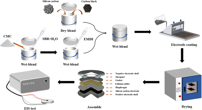
The structure of the button cell is shown in Fig. 2. A modified SiOx/C electrode was used as the positive electrode, and cut into electrode discs with a diameter of 14 mm using a cutting machine. A polypropylene (Celgard 2400) microporous diaphragm was used as the diaphragm, the electrolyte was LiPF6 dissolved in phosphate (ethylene carbonate![[thin space (1/6-em)]](https://www.rsc.org/images/entities/char_2009.gif) :
:![[thin space (1/6-em)]](https://www.rsc.org/images/entities/char_2009.gif) dimethyl carbonate
dimethyl carbonate![[thin space (1/6-em)]](https://www.rsc.org/images/entities/char_2009.gif) :
:![[thin space (1/6-em)]](https://www.rsc.org/images/entities/char_2009.gif) ethyl methyl carbonate = 1
ethyl methyl carbonate = 1![[thin space (1/6-em)]](https://www.rsc.org/images/entities/char_2009.gif) :
:![[thin space (1/6-em)]](https://www.rsc.org/images/entities/char_2009.gif) 1
1![[thin space (1/6-em)]](https://www.rsc.org/images/entities/char_2009.gif) :
:![[thin space (1/6-em)]](https://www.rsc.org/images/entities/char_2009.gif) 1) at a concentration of 1 M, and a lithium metal wafer was used as the counter electrode. Encapsulation of the button cell was performed in an argon-protected glove box (H2O < 0.01 ppm, O2 < 0.01 ppm), and the assembled button cell was left to stand for 24 h to allow the electrolyte to fully penetrate into the electrodes.
1) at a concentration of 1 M, and a lithium metal wafer was used as the counter electrode. Encapsulation of the button cell was performed in an argon-protected glove box (H2O < 0.01 ppm, O2 < 0.01 ppm), and the assembled button cell was left to stand for 24 h to allow the electrolyte to fully penetrate into the electrodes.
2.4. Test methods
2.4.1.1 Quasistatic uniaxial tensile test. The composite electrode was cut into rectangular specimens of 30 mm (L) × 6 mm (W), ensuring that the cuts were smooth and free of cracks. The electrode specimens were divided into two control groups, one of which was left untreated and the other of which was immersed in the electrolyte for 48 h. A dynamic mechanical analyser (DMA-Q800, TA, USA) was used to perform uniaxial tensile stretching of the two groups of electrode specimens at a constant strain rate of 0.1% min−1, and the stress–strain curves were obtained to determine the corresponding modulus of elasticity, tensile strength and elongation at break. For easy differentiation, electrode samples soaked in the electrolyte are called wet samples, and unsoaked samples are called dry samples.
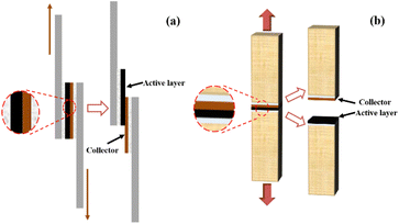
2.4.1.2 Interfacial strength experiment. The electrodes coated on copper foil were cut into rectangular sheets of 25 mm (L) × 12.5 mm (W) and fixed between a metal aluminium sheet and oak wood using highly adhesive 3 M double-sided tape, as shown in Fig. 3a and b. The specimens were tensile tested using an intelligent electronic tensile tester (XLW-EC, Labthink Electro-Mechanics, Jinan) to measure the interfacial shear strength and tensile strength between the electrode active layer and current collector.
2.4.3.1 Fourier transform infrared (FTIR) spectroscopy. FTIR spectroscopy (iS50 FT-IR, Nicolet, USA) was used to analyse the changes in the isocyanate groups and crosslinking reaction product groups in the adhesive film samples with different EMDI contents. The dried film sample was pressed under attenuated total reflectance (ATR) contact and scanned over wavelengths of 4000–675 cm−1 for 16 acquisitions, with a resolution of 4 cm−1 and an average penetration depth of 2.03 μm.
2.4.3.2 Specific surface area test (BET). A specific surface area analyser (ASAP 2460, Micromeritics, USA) was used to perform N2 adsorption–desorption tests on electrodes with different EMDI contents at 77.3 K to obtain parameters such as the specific surface area and pore size distribution of the samples.
3. Results and discussion
3.1. Effect of EMDI on the mechanical properties of the electrodes
During LIB charging and discharging, lithium ions will be embedded in the electrode, producing a certain volume expansion, which will generate local stresses and cause certain damage to the active layer. Therefore, for a battery to have good cycling performance, the active layer must have excellent resistance to deformation and damage.23,24 To study the impact of the EMDI content on the mechanical properties of SiOx/C electrode, we conducted a quasi-static uniaxial tensile test on the active layer of the ESiC-X electrodes. The stress–strain curves of dry and wet samples of SiOx/C electrodes with various EMDI contents are presented in Fig. 4. All electrode specimens exhibit minor elastic–plastic deformation with no distinct yielding behaviour and stretch by 0.4% to 1.7% prior to fracture. As the EMDI content increases, the tensile mechanical properties of both types of electrode samples initially increase and then decrease. Compared to the dry samples, the wet samples display significantly decreased tensile strength and elongation at break, which can be attributed to the dissolving effect of the electrolyte on the bonding agent, thereby reducing interfacial bonding performance.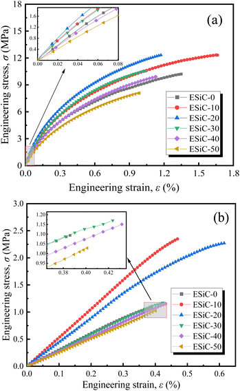 | ||
| Fig. 4 Uniaxial tensile stress–strain curves of SiOx/C electrodes with different EMDI contents: (a) dry samples and (b) wet samples. | ||
To better express the mechanical properties of the SiOx/C electrodes, we simplified the stress–strain curve to an elastic–plastic relationship. According to Fig. 4, the stress–strain curves of silicon–carbon electrodes are approximately linear in the interval of ε < 0.1%, and the slope gives the elastic modulus of the electrode by linearly fitting the data in this interval. The elastic modulus and tensile strength of the electrodes with different EMDI contents are shown in Fig. 5. Among the dry samples, the elastic modulus of ESiC-20 is the largest at 2.94 GPa, and the tensile strength of ESiC-10 is the largest at 11.82 MPa, which are 34.9% and 24.9% greater than those of ESiC-0. The elastic modulus and tensile strength of ESiC-10 are the highest among the wet samples, and are 72.4% and 114.7% greater than those of samples without EMDI.
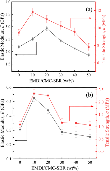 | ||
| Fig. 5 Elastic modulus and tensile strength of SiOx/C electrodes with different EMDI contents: (a) dry samples and (b) wet samples. | ||
The reason for this phenomenon is that the –NCO group in EMDI can react with the electrode particles and free hydroxyl groups on the surface of the conductive agent to form a strong chemical linkage, which results in the formation of an effective three-dimensional network structure between the various components of the composite material and significantly improves its macroscopic mechanical properties. However, the –NCO group also reacts with water or free carboxyl groups in the composites, generating carbon dioxide,25 which increases the internal defects of electrodes to a certain extent, leading to a decrease in their modulus and strength. Therefore, the addition of an appropriate amount of EMDI can improve the mechanical properties of silicon–carbon electrodes, while excessive addition will reduce their structural strength.
The interfacial bonding performance is an important indicator for evaluating the cycling performance of LIBs. A poor interfacial bonding performance will lead to debonding of the active layer and current collector, which will result in an increase in the internal resistance of the battery and deterioration of the cycling performance.26
To explore the effect of EMDI on the interfacial bonding performance of the electrodes, the ESiC-X electrodes were subjected to pull-shear and lap tests in this study, and the interfacial shear strength and interfacial tensile strength were determined, as shown in Fig. 6(a) and (b). The figure shows that the interface strength between the active layer and the collector fluid initially increases and then decreases with increasing EMDI content. When MEMDI/MCMC–SBR = 10%, the shear strength and tensile strength between the active layer and the current collector interface are the greatest at 0.12 MPa and 0.06 MPa, respectively, and are 11.9% and 34.1% greater than those when no EMDI is added. When the MEMDI/MCMC–SBR exceeds 10%, the interfacial strength gradually decreases with increasing EMDI content and is lowest at 50 wt%.
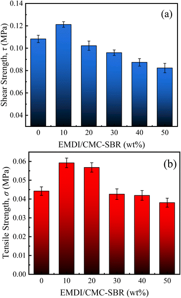 | ||
| Fig. 6 (a) Interfacial shear strength and (b) interfacial tensile strength between the active layer and current collector of the SiOx/C electrodes with different EMDI contents. | ||
The strength of interface between the active layer and current collector first increases and then decreases with increasing EMDI content. Several reasons can explain this observed trend. During the coating and moulding process of the composite slurry, water or metal oxide hydrates are adsorbed on the surface of the current collector metal. The –NCO group in EMDI reacts with water to form an amine, which will continue to react with the –NCO group to form urea, which can bond with metal oxides to form metal oxide complexes through hydrogen bonding. In addition, this group can also form covalent bonds with metal hydrates. As a result, EMDI improves the bonding strength of the composite to the current collector. However, simultaneously, –NCO reacts with water or carboxyl groups to produce CO2, leading to the formation of micropores at the bonding interface of the electrode during the drying process, which reduces its interfacial properties to a certain extent. Therefore, optimising of the interfacial properties of electrodes by adjusting the content of EMDI in the electrodes is important.
3.2. Effect of EMDI on the electrochemical performance of the electrodes
In this study, several electrochemical characterisation methods were used to evaluate the electrochemical performance of the EMDI-modified silicon–carbon electrodes, and the results are shown in Fig. 7. The EIS spectra and equivalent circuit diagrams of the electrodes with different EMDI contents are shown in Fig. 7a. According to the equivalent circuit model, the intercept in the high-frequency region represents the ohmic impedance (Rs) of the cell. The diameter of the semicircle in the middle and high-frequency regions represents the charge transfer impedance (Rct) at the electrolyte-active layer interface. A smaller semicircle indicates a lower charge transfer impedance. The diagonal line in the low-frequency region is influenced by the intra-electrode diffusion impedance, determined by the Warburg coefficient (σw), which can be calculated from eqn (1) and reflecting the lithium-ion diffusion capability at the electrode–electrolyte interface. Cdl represents the double electric layer capacitance, which can be calculated from eqn (2).27| Z′ = Rs + Rct + σww−1/2 | (1) |
 | (2) |
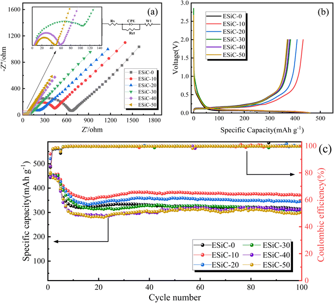 | ||
| Fig. 7 Electrochemical performance of modified electrodes: (a) AC impedance curve, (b) initial charge/discharge curve at a 0.02C rate, and (c) cycling performance and coulombic efficiency curve. | ||
| Sample | Rs (Ω) | Rct (Ω) | Cdl (μF) | σw (Ω s−1/2) |
|---|---|---|---|---|
| ESiC-0 | 13.54 | 658.6 | 1.13 | 1067.7 |
| ESiC-10 | 72.37 | 382 | 1.61 | 622.4 |
| ESiC-20 | 74.65 | 163 | 2.56 | 336.6 |
| ESiC-30 | 6.157 | 102.8 | 3.34 | 301.2 |
| ESiC-40 | 4.91 | 54.6 | 5.19 | 242.6 |
| ESiC-50 | 7.56 | 42 | 6.76 | 207.3 |
Fig. 7b shows the first-cycle voltage–charge/discharge capacity curves of the ESiC-X electrodes at a 0.02C. The results show that the initial discharge and charge capacities of the ESiC-10 electrode are 459.9 mA h g−1 and 432.4 mA h g−1, respectively, with an initial coulombic efficiency (ICE) of 94.02%. Compared with the ESiC-0 (ICE = 84.15%), ESiC-20 (ICE = 90.48%), ESiC-30 (ICE = 85.23%), ESiC-40 (ICE = 85.08%), and ESiC-50 (ICE = 80.47%) electrodes, the ESiC-10 electrode has a greater ICE. The ICE is mainly related to the formation of an SEI layer and the loss of active lithium and electrolyte.28 After the addition of a certain amount of the EMDI crosslinker, the pores inside the electrode obviously increase, the active substances are more easily activated, and the diffusion kinetics are enhanced. However, excessive porosity increases the contact area between the electrode material and the electrolyte, thus increasing the side reactions between them and reducing the ICE.29,30 Therefore, optimising of the electrochemical performance of these materials by tuning their porosity is important.
Fig. 7c shows the electrochemical performance of the ESiC-X electrodes after 100 cycles at a 0.2C, with the first four cycles of each sample tested at a low rate of 0.02C to fully activate the electrode material. The specific capacity of the ESiC-10 electrode is maintained at 371.3 mA h g−1 after 100 cycles at 0.2C, exhibiting the highest capacity retention of 80.73%. This result indicates that the capacity retention of the electrodes does not linearly increase with increasing EMDI content, which is mainly related to the interfacial properties of the electrode and the current collertor: an appropriate amount of EMDI can improve the interfacial properties of the electrode and the current collector, and at the same time, it can produce certain pores inside the electrode, which is conducive to lithium ion transmission. However, excessive EMDI can reduce the interfacial strength of the electrode and the current collector, leading to capacity decay and poor cycling performance of the battery.31,32 Therefore, adding appropriate amount of EMDI can effectively improve the electrochemical performance of electrode. At present, the price of EMDI is 2.5 USD per kg, and its addition accounts for less than 1% of the total cost of battery production. Meanwhile, in the electrode preparation process, the mass ratio of active particles, conductive agent and modified bonding agent is kept at 8![[thin space (1/6-em)]](https://www.rsc.org/images/entities/char_2009.gif) :
:![[thin space (1/6-em)]](https://www.rsc.org/images/entities/char_2009.gif) 1
1![[thin space (1/6-em)]](https://www.rsc.org/images/entities/char_2009.gif) :
:![[thin space (1/6-em)]](https://www.rsc.org/images/entities/char_2009.gif) 1, which does not reduce the relative content of active substances. Consequently, considering cost, performance and weight, we conclude that the addition of EMDI is a beneficial solution for battery technology.
1, which does not reduce the relative content of active substances. Consequently, considering cost, performance and weight, we conclude that the addition of EMDI is a beneficial solution for battery technology.
3.3. Effect of EMDI on the chemical structure and microstructure of the electrode materials
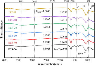
Fig. 8 presents the FTIR spectra of modified CMC–SBR polymer films at different EMDI contents. The FTIR spectra exhibits multiple absorption peaks, including C–H bending vibrations at 968 cm−1 and 910 cm−1, and a C–O stretching peak at 1060 cm−1. The characteristic peak at 1412 cm−1 may corresponds to the –COO− symmetric vibration of CMC. The peaks at 3403 cm−1 and 2920 cm−1 are associated with the stretching vibrations of –OH and C–H in the molecular chain, respectively.33,34 The degree of cross-linking in the aqueous polymer films is indicated by the intensity of the –NCO antisymmetric stretching peak at 2270 cm−1. The C![[double bond, length as m-dash]](https://www.rsc.org/images/entities/char_e001.gif) O stretching peaks between 1740–1598 cm−1 are composed of overlapping secondary products such as ureas and urethanes, making quantitative analysis of –NCO derivatives challenging. Therefore, we only discuss changes in the C
O stretching peaks between 1740–1598 cm−1 are composed of overlapping secondary products such as ureas and urethanes, making quantitative analysis of –NCO derivatives challenging. Therefore, we only discuss changes in the C![[double bond, length as m-dash]](https://www.rsc.org/images/entities/char_e001.gif) O peak region. It is evident that the –NCO peak in the infrared spectrum increases with higher EMDI content. Similarly, the peak at 1598 cm−1 also increases, indicating that the –NCO group cross-links with carboxyl groups in CMC. This cross-linking product is positively correlated with the EMDI concentration.
O peak region. It is evident that the –NCO peak in the infrared spectrum increases with higher EMDI content. Similarly, the peak at 1598 cm−1 also increases, indicating that the –NCO group cross-links with carboxyl groups in CMC. This cross-linking product is positively correlated with the EMDI concentration.
To assess the porosity characteristics of the modified electrodes, the specific surface area and porosity of the ESiC-X electrodes were measured by the N2 adsorption–desorption method, and the results are shown in Fig. 9 and Table 2. The N2 adsorption–desorption isotherms of each electrode illustrated in Fig. 9a are all type IV isotherms with obvious hysteresis loops, which indicates that the EMDI-modified electrodes have a layered stacked mesoporous structure.35 The pore size distribution determined with the Barrett–Joyner–Halenda (BJH) method is shown in Fig. 9b, with most mesopores having pore sizes distributed in the range of 3–12 nm, and some mesopores with a pore size of approximately 30 nm are also observed. The electrodes with EMDI added contain more mesopores than the electrode without EMDI.
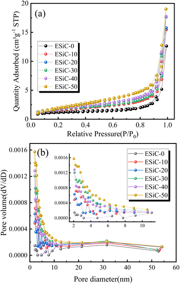 | ||
| Fig. 9 (a) N2 adsorption–desorption isotherms and (b) BJH pore size distribution curves for SiOx/C electrodes with different EMDI contents. | ||
| Sample | BET surface area (m2 g−1) | Pore volume (cm3 g−1) | Average pore diameter (nm) |
|---|---|---|---|
| ESiC-0 | 4.317 | 0.0074 | 6.864 |
| ESiC-10 | 5.670 | 0.0100 | 7.033 |
| ESiC-20 | 6.265 | 0.0107 | 6.830 |
| ESiC-30 | 6.556 | 0.0121 | 7.362 |
| ESiC-40 | 6.853 | 0.0114 | 6.666 |
| ESiC-50 | 7.940 | 0.0134 | 6.752 |
According to the results presented in Table 2, as the EMDI content in the electrode increased, the specific surface area and pore volume increase from 4.32 m2 g−1 and 0.0074 cm3 g−1 to 7.94 m2 g−1 and 0.0134 cm3 g−1, respectively. This result indicates that EMDI can significantly change the specific surface area and pore volume of silicon-carbon electrodes and form a porous structure. On the one hand, the appropriate amount of pores in the electrode material is conducive to the penetration of the electrolyte into the electrode, thus shortening the diffusion distance of lithium ions. On the other hand, these pores can enable adaptation to the volume changes of the electrode during the charging and discharging process and alleviate the volume expansion of the electrode.36–38 Furthermore, ESiC-10 was observed to possess a smaller surface area yet exhibit superior electrochemical performance. The specific surface area reflects the pore characteristics of the electrode, with increased pore structures facilitating ion transport channels, thereby enhancing diffusion kinetics.39 However, excessive pores can lead to more irreversible adverse reactions, thereby negatively affecting the electrochemical performance of the battery. Moreover, the cycle stability of a battery is closely linked to the interfacial performance between the electrode and the current collector. In Section 3.1, ESiC-10 demonstrated the best interface performance. Considering multiple factors, ESiC-10 exhibited excellent electrochemical performance.
4. Conclusions
In summary, this paper proposes a simple, safe, and efficient method for modifying silicon–carbon composite electrode materials. On the one hand, EMDI can form strong covalent bonds with free hydroxyl groups on the surface of water-based polymers, electrode particles, and conductive agents, significantly improving the macroscopic mechanical properties of the electrode. On the other hand, the electrode material can form a porous structure, which not only alleviates the volume expansion in the electrode lithiation process but also provides favourable transport channels for lithium ions, which ultimately enhances the electrochemical performance of the silicon–carbon electrode. By changing the proportion of EMDI in the electrode binder, the effect of its content on the mechanical and electrochemical properties of silicon–carbon electrode materials was explored, and the following conclusions can be drawn:(1) Adding EMDI with a mass ratio of 10–20% to the CMC–SBR bonding agent can significantly improve the tensile strength and elastic modulus of the active layer, but excessive EMDI will produce too many pores inside the electrode and reduce its structural strength.
(2) The ESiC-10 electrode possesses the best interfacial properties, with its interfacial shear strength and interfacial tensile strength improved by 11.9% and 34.1% compared with ESiC-0.
(3) EMDI can react with carboxyl groups or water to generate CO2, thus increasing the number of pores in the silicon–carbon electrode, and the electrochemical impedance of the electrode material decreases with increasing EMDI content.
(4) The ESiC-10 electrode has the best electrochemical cycling performance, with a capacity retention of 80.73% after 100 cycles at a rate of 0.2C.
Data availability
Data will be made available on request.Author contributions
Dongliang Liu: data curation, formal analysis, investigation, validation, writing – original draft. Detao Kong: data curation, formal analysis, validation. Qinghua Yang: investigation, validation. Yaolong He: data curation, formal analysis. Hongjiu Hu: writing – review & editing, project administration, supervision, resources, funding acquisition. All authors have read and agreed to the published version of the manuscript.Conflicts of interest
There are no conflicts to declare.Acknowledgements
The authors gratefully acknowledge the financial supports by the National Science Foundation of China under grant numbers 12272213 and 11872235.References
- B. Peng, Y.-L. Xu and F. M. Mulder, Acta Phys. Chim. Sin., 2017, 33, 2127–2132 CAS.
- X. Li, X. Qin, J. Li, S. Huang and X. Miao, Mater. Lett., 2020, 262, 127164 CrossRef CAS.
- Y. Yang, S. Wu, Y. Zhang, C. Liu, X. Wei, D. Luo and Z. Lin, Chem. Eng. J., 2021, 406, 126807 CrossRef CAS.
- Y. Cai, Y. Li, B. Jin, A. Ali, M. Ling, D. Cheng, J. Lu, Y. Hou, Q. He, X. Zhan, F. Chen and Q. Zhang, ACS Appl. Mater. Interfaces, 2019, 11, 46800–46807 CrossRef CAS PubMed.
- L. Zhu, F. Du, Y. Zhuang, H. Dai, H. Cao, J. Adkins, Q. Zhou and J. Zheng, J. Electroanal. Chem., 2019, 845, 22–30 CrossRef CAS.
- H. Zhang, K. Liu, Y. Liu, Z. Lang, W. He, L. Ma, J. Man, G. Jia, J. Cui and J. Sun, J. Power Sources, 2020, 447, 227400 CrossRef CAS.
- K.-C. Pu, X. Zhang, X.-L. Qu, J.-J. Hu, H.-W. Li, M.-X. Gao, H.-G. Pan and Y.-F. Liu, Rare Met., 2020, 39, 616–635 CrossRef CAS.
- Q. Man, Y. An, C. Liu, H. Shen, S. Xiong and J. Feng, J. Energy Chem., 2023, 76, 576–600 CrossRef CAS.
- S. Choi, T.-w. Kwon, A. Coskun and J. W. Choi, Science, 2017, 357, 279–283 CrossRef CAS PubMed.
- H. M. Jeong, B. S. Shin and S. Shin, Mass Spectrom. Lett., 2020, 11, 10–14 CAS.
- T. Zhang, L. Fu, J. Gao, L. Yang, Y. Wu and H. Wu, Pure Appl. Chem., 2006, 78, 1889–1896 CrossRef CAS.
- F. Luo, B. Liu, J. Zheng, G. Chu, K. Zhong, H. Li, X. Huang and L. Chen, J. Electrochem. Soc., 2015, 162, A2509–A2528 CrossRef CAS.
- M. Zhang, J. Li, C. Sun, Z. Wang, Y. Li and D. Zhang, J. Alloys Compd., 2023, 932, 167687 CrossRef CAS.
- D. Cheng, P. Ni, D. Qin, Y. Guo, S. Cai, Y. Liu, T. Rao, Y. Li and C. Wang, Solid State Ionics, 2023, 399, 116289 CrossRef CAS.
- P. Dong, X. Zhang, J. Zamora, J. McCloy and M.-K. Song, J. Energy Chem., 2023, 80, 442–451 CrossRef CAS.
- S. Lin, F. Wang and R. Hong, J. Colloid Interface Sci., 2022, 613, 857–865 CrossRef CAS PubMed.
- Z. Xu, X. Chu, K. Wang, H. Zhang, Z. He, Y. Xie and W. Yang, J Materiomics, 2023, 9, 378–386 CrossRef.
- Y. Ma, Y. Wang, Y. Zhang, H. Wang, J. Gu, N. Li and Y. Zhang, Int. J. Adhes. Adhes., 2023, 124, 103379 CrossRef CAS.
- Z. W. Wicks, Prog. Org. Coat., 1975, 3, 73–99 CrossRef CAS.
- J. Shi, N. Ehteshami, J. Ma, H. Zhang, H. Liu, X. Zhang, J. Li and E. Paillard, J. Power Sources, 2019, 429, 67–74 CrossRef CAS.
- X. Hu, Y. Li, Z. Chen, C. Duan, B. Yuan and S. Kawi, J. Power Sources, 2023, 568, 232964 CrossRef CAS.
- R. Wang, X. Li, Z. Wang and H. Zhang, Nano Energy, 2017, 34, 131–140 CrossRef CAS.
- W. Hao and J. Xie, J. Electrochem. Energy Convers. Storage, 2021, 18, 020909 CrossRef CAS.
- Y. Zhao, P. Stein, Y. Bai, M. Al-Siraj, Y. Yang and B.-X. Xu, J. Power Sources, 2019, 413, 259–283 CrossRef CAS.
- H. J. Hu, H. Liu, J. J. Zhao and J. Li, J. Adhes., 2006, 82, 93–114 CrossRef CAS.
- N. Iqbal, Y. Ali and S. Lee, J. Power Sources, 2020, 457, 228019 CrossRef CAS.
- T. Yuan, R. Tang, F. Xiao, S. Zuo, Y. Wang and J. Liu, Electrochim. Acta, 2023, 439, 141655 CrossRef CAS.
- J.-I. Hyun, K. Kong, S. Choi, M. Na, K. B. Kim, W. T. Kim and D. H. Kim, J. Power Sources, 2021, 495, 229802 CrossRef CAS.
- J. Shi, Y. Sun, Y. Peng, X. Jiang, J. Li, J. Chen and G. Liu, J. Energy Storage, 2024, 80, 110164 CrossRef.
- H. Xie, C. Hou, Y. Qu, H. Tian, H. Lu, J. Wu, S. Yang and Y. Ma, J. Energy Storage, 2023, 72, 108452 CrossRef.
- X. Zhang, W.-L. Song, H.-S. Chen and D. Fang, J. Power Sources, 2020, 465, 228290 CrossRef CAS.
- J. Chen, J. Liu, Y. Qi, T. Sun and X. Li, J. Electrochem. Soc., 2013, 160, A1502 CrossRef CAS.
- J. Zhang, N. Wang, W. Zhang, S. Fang, Z. Yu, B. Shi and J. Yang, J. Colloid Interface Sci., 2020, 578, 452–460 CrossRef CAS PubMed.
- H.-w. Jiang, Y. Yang, Y.-m. Nie, Z.-f. Su, Y.-f. Long, Y.-x. Wen and J. Su, RSC Adv., 2022, 12, 5997–6006 RSC.
- Z. Wang, B. Zheng, H. Liu, C. Zhang, F. Wu, H. Luo and P. Yu, J. Alloys Compd., 2021, 861, 157955 CrossRef CAS.
- S. Lou, X. Cheng, Y. Zhao, A. Lushington, J. Gao, Q. Li, P. Zuo, B. Wang, Y. Gao, Y. Ma, C. Du, G. Yin and X. Sun, Nano Energy, 2017, 34, 15–25 CrossRef CAS.
- Y. An, H. Fei, G. Zeng, L. Ci, S. Xiong, J. Feng and Y. Qian, ACS Nano, 2018, 12, 4993–5002 CrossRef CAS PubMed.
- C. Xu, B. Wang, H. Luo, P. Jing, X. Zhang, Q. Wang, Y. Zhang and H. Wu, ChemElectroChem, 2020, 7, 2889–2895 CrossRef CAS.
- T. Wu, M.-Y. Han and Z. J. Xu, ACS Nano, 2022, 16, 8531–8539 CrossRef CAS PubMed.
Footnote |
| † Both authors have contributed equally to the work. |
| This journal is © The Royal Society of Chemistry 2024 |

